In this article, we discuss 2 Wi-Fi vulnerabilities, CVE-2023-52160 and CVE-2023-52161

We will tell you how you can use a simple homemade device to intercept and emulate Wiegand signals, opening doors without authorization. We will describe in detail the process of creating such a device, connecting it to the system, and demonstrate how easy it is to bypass seemingly reliable protection. This material is intended for information security specialists, ACS developers, and anyone interested in increasing the level of protection of their systems.

Imagine the situation: expensive locks and modern access cards are installed, and someone with a small device in their pocket opens them in a matter of minutes. It sounds like a scene from a cyberpunk movie, but in reality it is commonplace. Many access control systems are still based on a protocol created back in the 70s, without any encryption or protection against interception.
We are talking about Wiegand – an outdated technology, the vulnerability of which was demonstrated in practice. A compact device was assembled that is able to intercept system signals, copy access cards and reproduce them exactly at the right moment.
This example is not published to teach you how to hack systems – those who want to have such instructions have long found such instructions on their own. The main purpose is to remind you: using technology that is more than half a century old in critical infrastructure is risky. Especially in 2025, when cyber threats are developing faster than ACS are being updated.
We came across the Wiegand protocol – a real dinosaur in the world of access control systems. The history of this standard began in the 70s with an interesting technology – plastic cards with fused wire segments made of an alloy of iron, cobalt and vanadium. This material was named after its inventor, John R. Wiegand.
Wiegand cards were distinguished by their exceptional simplicity due to their design – they worked on the basis of the physical properties of the material itself. They did not need batteries, they were not afraid of moisture and were not subject to demagnetization. It was enough to pass such a card past the reader – and the built-in wires alternately created a sequence of electrical pulses.
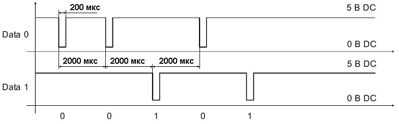
The most common format – Wiegand-26 – involves data transmission over two lines: one is responsible for zeros, the other for ones. In total, 26 bits are transmitted, of which 2 are used for parity control, and the remaining 24 are the data itself. No encryption, no protection against interception – everything remained at the level of the 70s, when the calculator was the smartest device in the office.
Time passed, technologies changed: first magnetic cards, then contactless RFID, then biometrics appeared. But the Wiegand protocol itself remained practically unchanged legacy. The ACS industry clung to it with a death grip.
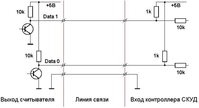
Manufacturers can be understood: firstly, Wiegand is incredibly simple to implement – only three wires (DATA0, DATA1 and ground), and secondly, why change something that seems to be functioning, if the replacement will require millions for new equipment?
As a result, it turned out that even in 2025, the biometric access control system in our office is based on a protocol created back in the 70s. During a security discussion in the conference room, someone from the team thoughtfully said: “Wait, if this protocol is so elementary… can we just eavesdrop on it?”
We decided to test the assumption in practice. If even the most modern system ultimately transmits data in the open over two wires, it doesn’t matter whether it reads a fingerprint, a face, or a regular card. In the end, it all comes down to the same vulnerable bits without protection.
And if Wiegand is just two wires with a sequence of pulses, in theory it is enough to connect to them, record these pulses, and simply play them back at the right moment.
This is how the idea of our implant was born – a mini-device that simply connects to the wires and quietly collects the identifiers of everyone who passes through the door. And when necessary, reproduces them. The main focus here is that the controller does not even suspect the substitution and thinks that he is communicating with his native reader. We immediately decided that the device should be compact, ideally the size of a coin.
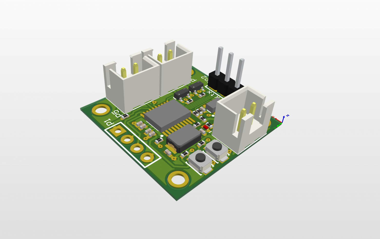
We started with the design. In just a couple of evenings, we sketched out the schematic diagram and built the board. At the same time, we decided on the component base. Given the simplicity of the protocol, the most basic microcontroller was enough for us. We settled on the STM32 F0 series with minimal wiring – a good compromise between accessibility and functionality.
The prototype turned out to be really tiny – only 25×25 mm, and a significant part of the space is taken up by the connectors. If you replace them with soldered wires and use a double-sided board, the dimensions will be even smaller.
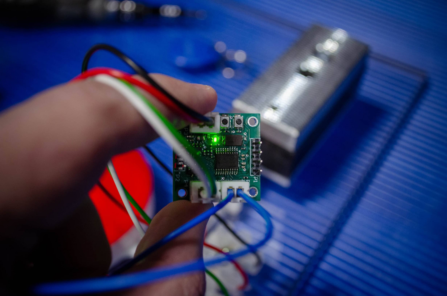
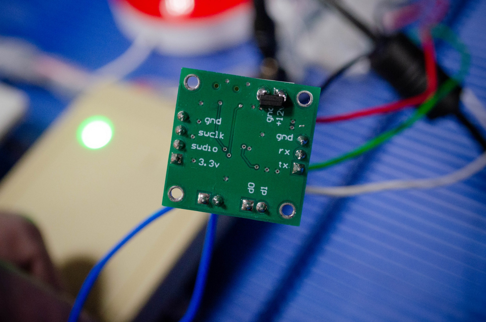
Now let’s take a closer look at the baby. To connect to the Wiegand lines, we use standard terminal blocks: two signal wires and a common wire for the return current.
To communicate with the computer, we added a UART port with a simple three-pin connector (RX, TX, GND). A standard USB-TTL converter connects to it.
All this beauty is controlled by two buttons: press one – the device emulates the recorded identifiers, press the other – the memory is cleared. We even added a jumper that starts the process of emulating the sending of identifiers.
The firmware was written in C in the Cube IDE environment, a typical tool for working with STM32 microcontrollers. But there was a problem right from the start: our microchip had very limited resources, so we had to work seriously on optimization. The code was rewritten from scratch several times – there was simply not enough memory to store the card numbers.
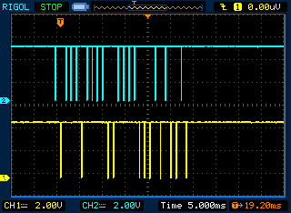
The device’s operation is based on precise adherence to the protocol’s time parameters. When a pulse appears on the line, the microcontroller checks its duration – in the Wiegand protocol it should be approximately 200 microseconds.
If the signal meets the standard, the device begins to collect bits one by one into a single packet, like a puzzle – piece by piece. When all the bits are received, a parity check is performed. If everything is correct – the identifier is written to memory. Up to 100 different values can be stored.
When the device switches to the “reader replacement” mode, the process occurs in reverse order. It generates exact copies of the DATA0 and DATA1 signals, clearly repeating the stored bits. The ACS does not suspect anything – the system thinks it is dealing with the original, trusted reader.
// фрагмент коду передачі бітів

if(bit_level_state == LEVEL_HIGH) // якщо рівень сигналу на лінії високий
{
    bit_delay++;

    if(bit_delay > 9) // робимо затримку 2000 мкс. між початком першого та другого біта
    {
    	bit_delay = 0;

    	if(transfer_bit_counter > 0) // якщо лічильник біт на передачу ще не обнулився
    	{
        	if( ( (rfid_number_wiegand_transfer >> (transfer_bit_counter-1)) & 0x01 ) == 0x01 ) // якщо біт на передачу дорівнює 1
        	{
            	HAL_GPIO_WritePin(PORT_WRITE_1, PIN_DATA_WRITE_1, GPIO_PIN_SET); // виставляємо у низький стан на порту W1
            	transfer_bit_counter--; // зменшуємо лічильник передачі бітів
            	bit_level_state = LEVEL_LOW; // виставляємо низький стан на лінії
        	}
        	else // якщо біт на передачу дорівнює 0
        	{
            	HAL_GPIO_WritePin(PORT_WRITE_0, PIN_DATA_WRITE_0, GPIO_PIN_SET); // виставляємо у низький стан на порту W0
            	transfer_bit_counter--; // зменшуємо лічильник передачі бітів
            	bit_level_state = LEVEL_LOW; // виставляємо низький стан на лінії
        	}


    	}
    }
}
else if(bit_level_state == LEVEL_LOW) // якщо рівень сигналу на лінії низький
{
    HAL_GPIO_WritePin(PORT_WRITE_0, PIN_DATA_WRITE_0, GPIO_PIN_RESET); // виставляємо у високий стан на порту W0
    HAL_GPIO_WritePin(PORT_WRITE_1, PIN_DATA_WRITE_1, GPIO_PIN_RESET); // виставляємо у високий стан на порту W1
    bit_level_state = LEVEL_HIGH;
    if(transfer_bit_counter == 0)
    {
    	data_transfer_state = DATA_TRANSFER_END; // передача закінчена
The most impressive thing is that all this logic fits into literally a few hundred lines of code. For clarity, an example has been added to show how simple it all works. Of course, there are many subtleties, optimizations, and technical details in the firmware, but the general principle remains elementary.
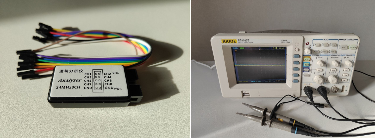
We decided to approach the matter thoroughly and collected a set of measuring equipment: a Rigol DS1052E oscilloscope for signal analysis, a Fluke 28-II multimeter (not the cheapest, by the way) for checking voltage levels, and a Saleae Logic logic analyzer for detailed protocol analysis.
Testing the implant took place in stages — as befits engineers. First, they checked each individual component, as if they were conducting unit tests, only not in the code, but on the hardware. “Does the microcontroller work? Yes! Do the buttons respond? Great!” When they started to combine everything into a single system — the most interesting thing began.
As often happens, practice made its own adjustments. The theory looks clear and neat, but in reality there are nuances that are not mentioned in the textbooks. Surprises began to creep out — sometimes something is not read, sometimes the data is distorted.
A special challenge arose with the code. It was necessary to squeeze a bunch of logic into the limited memory of the microcontroller and also adhere to microscopic timing accuracy. The slightest deviation in the pulse length — and the ACS controller simply does not recognize the transmitted data.
Then — more. It turned out that different manufacturers of ACS interpret the Wiegand standard in their own way. Some have longer pulses, others have shorter ones, and some even change the intervals between bits. It seems that each manufacturer is trying to deviate as much as possible from the original specification.
They started with support for the classic Wiegand-26, but during the tests they gradually added formats of 34, 42, 48 bits and others – because in practice you have to deal with everything that is possible.
We had to dive headfirst into the technical documentation. Imagine how long it takes to understand dozens of specifications — especially when every second one includes phrases like “recommended value, which may vary depending on implementation.”
To conduct the experiment as objectively as possible, we collected a selection of different readers. They all used the basic Wiegand architecture, but each one “fantasized” in its own way. Most often, there were variations in the duration of the bits and the length of the pauses between them — sometimes longer, sometimes shorter, without any system.
As a result, we had to calculate the average timing value, which worked stably on all tested devices. This became the basic setting in our firmware.
After all the experiments and adjustments, a full-fledged test stand was assembled — it almost completely imitated a regular office access point.
At the center of the design is a compact controller, by the way, manufactured by Bastion (it turned out to be ironic, right?). A real electromagnetic lock with an exit button was connected to it, an RFID reader for access cards was installed. And to make everything look even more atmospheric, a bit of nostalgia was added — an iButton reader, the same one for round metal “tablets”.
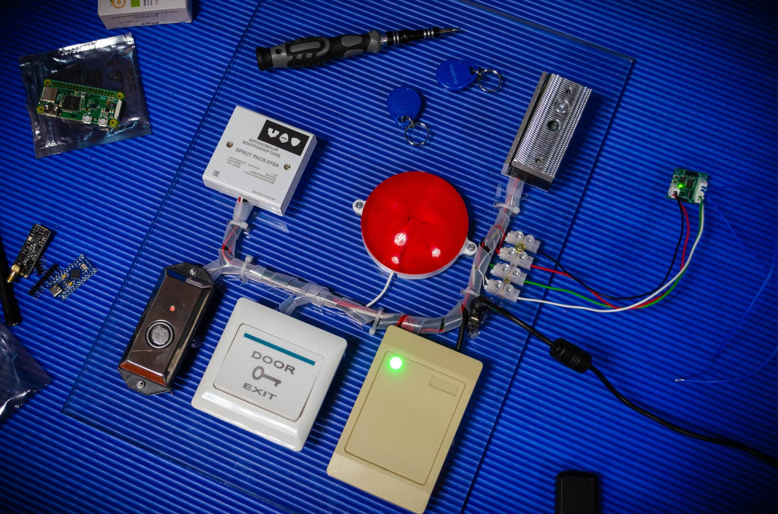
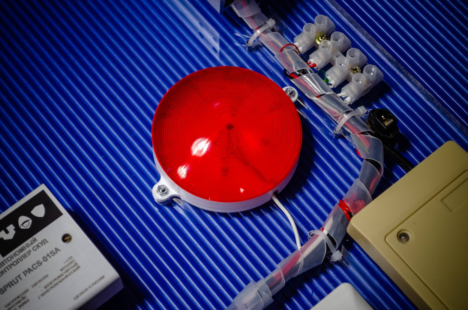
To add to the spectacle, a large red lamp was connected to the stand — it flashed every time the implant successfully intercepted or emulated a code. In real conditions, such “illumination” is, of course, superfluous, but for demonstrations, the effect is just right.
The most interesting thing began when we moved on to the final tests on operating ACS. A huge thank you to colleagues from our former job who allowed us to use their systems for tests — they became the first “volunteers” in our field experiment.
And then it finally became clear: everything is much simpler than it seems. Want to bypass a security system worth millions? Find four wires on the reader. Two — power (plus and minus 12 volts), two more — data lines (usually green W0 and white W1). Even the color marking is standard.
Next — almost funny. Carefully remove the reader — in most cases, it’s just two screws. Our implant is connected to the wires, everything is neatly put in place. Now everyone who inserts their card, without suspecting it, transmits their code to us – the device silently intercepts the signal and stores it.
We return later, remove the implant and reproduce the desired identifier. The perfect crime – if we really were the attackers.
And nothing complicated: you don’t need to be a hacker from a movie. Just a little ingenuity, a basic board with a few components and a few free evenings.
The creation of this implant is only the first chapter of the story. We have already determined the next directions for development. We are currently studying more modern protocols to understand how resistant they are to attacks that have already shown their effectiveness on the example of Wiegand.
Our miniature board still has a lot of potential. It can be equipped with a full-fledged RFID reader with a separate antenna, as well as add a wireless module, for example, LoRa. This will allow data to be collected remotely, without even approaching the object – ideal for covert monitoring.
If we talk about the conclusions from the entire experiment, then it is as simple as possible: in 2025, using Wiegand on serious objects is the same as trying to protect a bank safe with a mailbox lock.
Of course, there are ways to partially reduce the risks – hide the wiring, install cameras, regularly check the equipment. But this is more like patching holes than real protection. A complete solution requires a systemic approach: manufacturers should stop supporting protocols from the last century, and users should evaluate the security of ACS not by design and brochures, but by real resistance to modern threats.
I want to believe that this experiment will force at least someone from the industry to take security issues more seriously. Because technology is moving forward, and attacks are even faster.