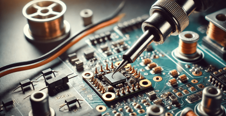

Soldering FPV drones requires precision, experience and quality materials. In this article, we will look at soldering techniques, the main mistakes and how to avoid them. Learn how to achieve a quality result when tinning contact pads, preparing wires and soldering them. Get advice on choosing tools, temperatures and materials for soldering, as well as advice from professionals to help make the soldering process efficient and safe.
The contact pads are completely covered with solder, including the power pads on the underside of the ESC
The non-insulated part of the wire is completely immersed in the drop of solder on the contact area and does not protrude beyond it
Solder forms a shiny round drop
Soldering looks neat and is strong
All wires are soldered according to the pinouts
A properly selected and sufficiently powerful soldering iron (from 65 watts) and high-quality materials: solder and flux will provide you with a painless soldering experience.
Materials that will be easy to work with:
Soldering iron – Quecoo T12-956. It will require a massive tip for soldering power contacts. (for example, K, C3, C4).
Solder – Cynel Sn60Pb40 0.8-1mm
Soldering gel fluxes – KEK TS-559-ASM (in a syringe), Pasta do lutowania TermoPasty
Set the required temperature on the soldering iron – 400-450 degrees for ESC power contacts, 310-330 degrees for all other contacts (depending on your soldering iron).
Apply flux to the contact area.
Clean the tip of the soldering iron.
Attach the tip of the soldering iron to the contact pad and apply solder. Spread the solder over the entire surface of the site with the movement of the needle. Do not wait longer than necessary so that the flux does not evaporate and the solder does not start to stick to the tip.
The result: the contact area is completely covered with solder, which forms a neat drop. The power pads must be soldered on both sides of the circuit board.
Remove some insulation from the wire, twist the cores so that they do not loosen. If the wire comes already tinned from the manufacturer, it still needs to be tinned.
The length of the uninsulated part of the wire should be approximately 2/3 of the length of the contact pad to be soldered.
Apply flux to the bare part of the wire.
Set the temperature of the soldering iron to 310-330 degrees.
Clean the tip of the soldering iron.
Take some solder on the tip and apply it to the bare part of the wire. You can turn the wire so that it is well twisted from all sides.
Result: The exposed part of the wire is completely tinned, no cores are visible, the cores do not stick out.
Apply flux to the tinned contact area.
Set the temperature of the soldering iron to 400-450 degrees for power pads, 310-330 degrees for all others (depending on your soldering iron).
Clean the tip of the soldering iron.
Put some solder on the tip.
Bring the tip to the contact pad, wait for the solder to melt, and feed the wire into the drop. Do not press the wire strongly with the sting, so that the veins do not loosen.
Remove the tip of the soldering iron and look at the work. If necessary – add flux, solder and heat again to get a nice solid drop.
After soldering, be sure to wash the flux with isopropyl alcohol.
Result: The uninsulated part of the wire is completely immersed in a shiny neat drop of solder on the contact pad.
List of typical errors and recommendations for their elimination. Check your soldering to make sure everything is fine.
The contact areas are not completely cemented
Too much insulation removed / exposed wire outside the solder drop
Poorly soldered wires
Cold soldering
Insufficient contact area / bare wire not immersed in solder drop
Stalagmites
Too much solder
Not enough solder
Solder drops on the board / soldered adjacent pads
Non-conformity of soldering to defoamers
If the contact areas are not completely covered with solder and copper is visible, this will reduce the contact area, which will negatively affect the reliability of the connection.
How to fix?
Apply flux, heat the area with a soldering iron (420-450°C for power contacts, 320-350°C for others), and unsolder the wire. If necessary, add more flux. Take the solder, bring it to the pad with the soldering iron tip, and solder the surface to completely cover the copper.
The wire insulation must be removed so that it fits tightly to the solder drop. The optimal length of the bare wire is about two-thirds of the size of the contact area. If the bare wire protrudes beyond the drop, the connection must be redone.
How to fix?
Unsolder the wire, shorten it, solder it if necessary and solder it again. Remember to add flux and regularly clean the soldering iron tip for best results.
This problem is usually seen together with the previous one. If you see exposed wires or individual wires sticking out in different directions, this indicates that the wire was not properly soldered. Bare wire without protection becomes more fragile and can break over time, or individual cores can cause a short circuit when contacting other sites.
How to fix?
It is necessary to unsolder the wire, if necessary, shorten it and solder it completely, then solder it again.
Cold soldering occurs when the temperature of the soldering iron is not high enough, the wrong tip or poor-quality solder is used. In this case, the solder does not melt completely, forms layers instead of a homogeneous drop, which do not connect well with each other and can easily break off under load.
How to fix?
Make sure the solder meets the guidelines, the soldering iron is at the right temperature, and the tip is big enough for the job. Apply flux and heat the area with a soldering iron at a slightly higher temperature until the solder is completely melted.
If the wire does not provide sufficient contact with the site, its conductivity will be reduced, and under loads, the connection may weaken or come off completely.
How to fix?
Apply flux, heat the contact, move the wire closer to the pad and add solder to form a secure blob. However, it is often more difficult to fix such a mistake than to redo everything from scratch. The best solution is to unsolder the wire, apply flux, re-solder the pad and wire if necessary, and then resolder them.
How to fix?
Add flux and heat the soldering point with the tip of the soldering iron so that the solder spreads and forms a neat drop.
Too much solder can impair electrical conductivity and prevent the connection from working properly. A large drop of solder on the power contacts can touch the frame or connector on the flight controller, which can cause a short circuit or malfunction of the controller.
How to fix?
Add flux, heat the contacts, unsolder the wire, clean the excess solder from the platform and the wire, solder again and solder.
If the wire is only superficially “stuck” to the contact area, and not immersed in a reliable rounded drop of solder, this indicates an insufficient amount of solder during soldering.
How to fix?
Apply flux to the soldering point, clean the tip of the soldering iron, collect the solder and apply it to the soldering point while holding the wire. It is often more difficult to fix such a mistake than to start over. The best option would be to unsolder the wire, add flux, solder the pad and wire again, and then solder them again.
One of the common mistakes in soldering is the mismatch of the pinout, due to which incorrectly soldered devices will not work.
The most common mistakes:
the polarity of the capacitor is reversed (this will lead to a short circuit)
confused RX and TX from the receiver
tangled video cables and video transmitter data cable
How to fix?
It is necessary to unsolder the erroneously soldered wire and solder it to the correct place.
Quality soldering is a key step in building a reliable and efficient FPV drone. Following proper technique, using quality materials, and paying attention to detail will help avoid common mistakes that can lead to short circuits or unreliable connections. Always check your soldering, flux and cleanliness of working tools to ensure stable operation of your drone in flight.
