
TinyUSB greatly simplifies working with USB in microcontrollers and allows you to create multifunctional USB devices without deep diving into the protocol specification. Using the STM32WB55 as an example, our subscriber showed how to implement a flash drive, virtual COM port, and HID music control via a single USB interface.
If you happen to have a microcontroller (from now on simply “MCU”) with USB support lying around and have always wanted to see how USB actually works under the hood, let’s figure it out together. So, what we’ll need is an MCU with USB support, the TinyUSB software stack, and a bit of spare time. We’re going to build a USB flash drive, a multimedia controller for music playback on a PC, and a virtual COM port.
TinyUSB is a library for working with USB peripherals on microcontrollers, designed with portability, performance, and memory safety in mind thanks to static memory allocation. It acts as a bridge between the hardware USB peripheral inside the microcontroller and our application code. The library hides most of the low-level complexity of dealing with the USB controller directly. It officially supports more than 50 MCU families from different vendors, including STM32, ESP32, RP2040, NRF, MSP, and many others.
Raspberry Pi Pico (RP2040, RP2350) even adopted TinyUSB as the default USB implementation inside the Pico SDK. Other vendors usually provide their own proprietary USB stacks, but if portability and open-source matter to you, TinyUSB is definitely the better choice.
Let’s take a look at TinyUSB integration using an STM32WB55-based board as an example. This demo project is available on GitHub, and there’s also a video demo linked at the end of the article.
🏋🏻♂️ Hardware
TinyUSB itself does not generate the famous differential USB signals (D+ and D−) directly. Instead, it fully relies on the USB peripheral built into the MCU hardware. In other words, the microcontroller must already include a physical USB controller provided by the manufacturer. So before doing anything else, we need to enable it properly by configuring the clocks and initializing the peripheral itself.
STMicroelectronics has long adopted the practice of adding high-precision internal oscillators (HSI48) to their USB-capable MCUs, since USB requires a very accurate clock source. Thankfully, this means we usually don’t need to place an external crystal on the PCB specifically for USB operation.
However, internal oscillators have their downsides: their accuracy depends on ambient temperature and stable supply voltage. Fortunately, STM32 chips also include a dedicated compensation system called CRS (Clock Recovery System), which helps mitigate these issues.
So before integrating TinyUSB, all of this needs to be configured and initialized correctly. For my STM32WB55, it looks like this:
void SystemClock_Config(void) {
  RCC_OscInitTypeDef RCC_OscInitStruct = {0};
  RCC_ClkInitTypeDef RCC_ClkInitStruct = {0};
  RCC_CRSInitTypeDef RCC_CRSInitStruct = {0};

  /** Configure the main internal regulator output voltage
   */
  __HAL_PWR_VOLTAGESCALING_CONFIG(PWR_REGULATOR_VOLTAGE_SCALE1);

  /** Initializes the RCC Oscillators according to the specified parameters
   * in the RCC_OscInitTypeDef structure.
   */
  RCC_OscInitStruct.OscillatorType = RCC_OSCILLATORTYPE_HSI48 |
                                     RCC_OSCILLATORTYPE_HSI |
                                     RCC_OSCILLATORTYPE_HSE;
  RCC_OscInitStruct.HSEState = RCC_HSE_ON;
  RCC_OscInitStruct.HSIState = RCC_HSI_ON;
  RCC_OscInitStruct.HSI48State = RCC_HSI48_ON;
  RCC_OscInitStruct.HSICalibrationValue = RCC_HSICALIBRATION_DEFAULT;
  RCC_OscInitStruct.PLL.PLLState = RCC_PLL_ON;
  RCC_OscInitStruct.PLL.PLLSource = RCC_PLLSOURCE_HSE;
  RCC_OscInitStruct.PLL.PLLM = RCC_PLLM_DIV2;
  RCC_OscInitStruct.PLL.PLLN = 8;
  RCC_OscInitStruct.PLL.PLLP = RCC_PLLP_DIV2;
  RCC_OscInitStruct.PLL.PLLR = RCC_PLLR_DIV2;
  RCC_OscInitStruct.PLL.PLLQ = RCC_PLLQ_DIV2;
  if (HAL_RCC_OscConfig(&RCC_OscInitStruct) != HAL_OK) {
    Error_Handler();
  }

  /** Configure the SYSCLKSource, HCLK, PCLK1 and PCLK2 clocks dividers
   */
  RCC_ClkInitStruct.ClockType = RCC_CLOCKTYPE_HCLK4 | RCC_CLOCKTYPE_HCLK2 |
                                RCC_CLOCKTYPE_HCLK | RCC_CLOCKTYPE_SYSCLK |
                                RCC_CLOCKTYPE_PCLK1 | RCC_CLOCKTYPE_PCLK2;
  RCC_ClkInitStruct.SYSCLKSource = RCC_SYSCLKSOURCE_PLLCLK;
  RCC_ClkInitStruct.AHBCLKDivider = RCC_SYSCLK_DIV1;
  RCC_ClkInitStruct.APB1CLKDivider = RCC_HCLK_DIV1;
  RCC_ClkInitStruct.APB2CLKDivider = RCC_HCLK_DIV1;
  RCC_ClkInitStruct.AHBCLK2Divider = RCC_SYSCLK_DIV2;
  RCC_ClkInitStruct.AHBCLK4Divider = RCC_SYSCLK_DIV2;

  if (HAL_RCC_ClockConfig(&RCC_ClkInitStruct, FLASH_LATENCY_3) != HAL_OK) {
    Error_Handler();
  }

  /** Enable the SYSCFG APB clock
   */
  __HAL_RCC_CRS_CLK_ENABLE();

  /** Configures CRS
   */
  RCC_CRSInitStruct.Prescaler = RCC_CRS_SYNC_DIV1;
  RCC_CRSInitStruct.Source = RCC_CRS_SYNC_SOURCE_USB;
  RCC_CRSInitStruct.Polarity = RCC_CRS_SYNC_POLARITY_RISING;
  RCC_CRSInitStruct.ReloadValue =
      __HAL_RCC_CRS_RELOADVALUE_CALCULATE(48000000, 1000);
  RCC_CRSInitStruct.ErrorLimitValue = 34;
  RCC_CRSInitStruct.HSI48CalibrationValue = 32;

  HAL_RCCEx_CRSConfig(&RCC_CRSInitStruct);
}
The easiest way to generate this code is by using STM32CubeMX, a dedicated visual configuration tool for STM32 microcontrollers.
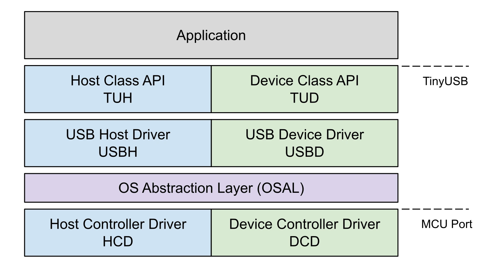
Now we can finally move on to integrating the middleware layer — TinyUSB. The term “middleware” is important here because it highlights TinyUSB’s role in this whole setup. The library sits right between the hardware layer — the MCU’s USB peripheral — and the application code written by the developer.
The MCU’s USB controller handles the actual electrical signaling, while the library itself takes care of the USB protocol and communication with the host, such as a PC that our USB device will be connected to. That leaves the developer responsible only for writing the firmware.
The TinyUSB library is hosted on GitHub, so the most logical way to integrate it into your project is either:
adding it as a git submodule
or simply downloading the archive manually
After that, depending on your build system or development environment, you just include the required .h and .c files. In my case, this is a CMake-based project, so I simply connected TinyUSB as a git submodule and added the necessary files into CMakeLists.txt.
The next step is configuring the library itself. For this, we’ll need two configuration files:
tusb_config.h
usb_descriptors.c
The first one is simpler and more generic. It describes things like:
the MCU family being used (
OPT_MCU_STM32WBin my case)
the USB operating speed mode (USB Low Speed — 1.5 Mb/s, Full Speed — 12 Mb/s, etc.)
whether the project uses an RTOS or runs without one
whether the device will operate as a USB host or as a USB peripheral device
which USB classes will be enabled (for example: MSC as a flash drive, HID as a keyboard/mouse/gamepad, CDC as a COM port, and others)
the sizes of RX/TX buffers used for incoming and outgoing data
The easiest way to create this configuration file is to copy one from the official examples and modify it for your MCU and your specific use case. In fact, this is exactly what the TinyUSB developers themselves recommend.
For example, you can enable multiple USB classes at the same time, and your device will simultaneously work as:
a USB flash drive
an audio device
a virtual COM port
or any combination you need
The second configuration file, usb_descriptors.c, contains more detailed information that will be exposed to the host system about our device.
This includes things like:
which USB classes the device implements
the device manufacturer name
serial number
power consumption
and other descriptor-related information
This file is also best copied from an existing example and then customized for your project.
At this stage, it’s highly recommended to have at least a basic understanding of how USB works internally: descriptors and their types, USB classes, interfaces, and endpoints. Covering all of that is beyond the scope of this article, so it’s worth watching a dedicated video or taking a short course on the topic.
And if you’re interested in the low-level electrical and signaling side of USB itself, Ben Eater has an excellent video called How does a USB keyboard work?
So, for our example project, we’ll create a configuration where the STM32WB55-based device will operate as a USB peripheral connected to a host system, while simultaneously functioning as:
a virtual COM port
and a USB flash drive
#ifndef TUSB_CONFIG_H_
#define TUSB_CONFIG_H_

#ifdef __cplusplus
extern "C" {
#endif

//--------------------------------------------------------------------+
// Board Specific Configuration
//--------------------------------------------------------------------+

// RHPort number used for device can be defined by board.mk, default to port 0
#ifndef BOARD_TUD_RHPORT
#define BOARD_TUD_RHPORT 0
#endif

// RHPort max operational speed can defined by board.mk
#ifndef BOARD_TUD_MAX_SPEED
#define BOARD_TUD_MAX_SPEED OPT_MODE_FULL_SPEED
#endif

//--------------------------------------------------------------------
// Common Configuration
//--------------------------------------------------------------------

// defined by compiler flags for flexibility
#define CFG_TUSB_MCU OPT_MCU_STM32WB
#ifndef CFG_TUSB_MCU
#error CFG_TUSB_MCU must be defined
#endif

#ifndef CFG_TUSB_OS
#define CFG_TUSB_OS OPT_OS_NONE
#endif

#ifndef CFG_TUSB_DEBUG
#define CFG_TUSB_DEBUG 0
#endif

// Enable Device stack
#define CFG_TUD_ENABLED 1

// Default is max speed that hardware controller could support with on-chip PHY
#define CFG_TUD_MAX_SPEED BOARD_TUD_MAX_SPEED

/* USB DMA on some MCUs can only access a specific SRAM region with restriction
* on alignment. Tinyusb use follows macros to declare transferring memory so
* that they can be put into those specific section. e.g
* - CFG_TUSB_MEM SECTION : __attribute__ (( section(".usb_ram") ))
* - CFG_TUSB_MEM_ALIGN   : __attribute__ ((aligned(4)))
*/
#ifndef CFG_TUSB_MEM_SECTION
#define CFG_TUSB_MEM_SECTION
#endif

#ifndef CFG_TUSB_MEM_ALIGN
#define CFG_TUSB_MEM_ALIGN __attribute__((aligned(4)))
#endif

//--------------------------------------------------------------------
// DEVICE CONFIGURATION
//--------------------------------------------------------------------

#ifndef CFG_TUD_ENDPOINT0_SIZE
#define CFG_TUD_ENDPOINT0_SIZE 64
#endif

//------------- CLASS -------------//
#define CFG_TUD_CDC 1
#define CFG_TUD_MSC 1
#define CFG_TUD_HID 1

#define CFG_TUD_CDC_NOTIFY 1 // Enable use of notification endpoint

// CDC FIFO size of TX and RX
#define CFG_TUD_CDC_RX_BUFSIZE (TUD_OPT_HIGH_SPEED ? 512 : 64)
#define CFG_TUD_CDC_TX_BUFSIZE (TUD_OPT_HIGH_SPEED ? 512 : 64)

// CDC Endpoint transfer buffer size, default to max bulk packet size (HS 512,
// FS 64). Larger is faster. Larger RX_EPSIZE requires CFG_TUD_CDC_RX_NEED_ZLP =
// 1 and host ZLP support
#define CFG_TUD_CDC_RX_EPSIZE (TUD_OPT_HIGH_SPEED ? 512 : 64)
#define CFG_TUD_CDC_TX_EPSIZE (TUD_OPT_HIGH_SPEED ? 512 : 64)

// MSC Buffer size of Device Mass storage
#define CFG_TUD_MSC_EP_BUFSIZE 512

// HID buffer size (consumer control report = 2 bytes, keep some margin)
#define CFG_TUD_HID_EP_BUFSIZE 16

#ifdef __cplusplus
}
#endif

#endif /* TUSB_CONFIG_H_ */
  #include "tusb.h"

// Endpoint numbers
#define EPNUM_CDC_NOTIF   0x81
#define EPNUM_CDC_OUT     0x02
#define EPNUM_CDC_IN      0x82
#define EPNUM_MSC_OUT     0x03
#define EPNUM_MSC_IN      0x83
#define EPNUM_HID_IN      0x84

// Interface numbers
enum {
ITF_NUM_CDC = 0,
ITF_NUM_CDC_DATA,
ITF_NUM_MSC,
ITF_NUM_HID,
ITF_NUM_TOTAL
};

// String descriptor indices
enum {
STRID_LANGID = 0,
STRID_MANUFACTURER,
STRID_PRODUCT,
STRID_SERIAL,
STRID_CDC,
STRID_MSC,
STRID_HID,
};

//--------------------------------------------------------------------+
// Device descriptor
//--------------------------------------------------------------------+

tusb_desc_device_t const desc_device = {
.bLength            = sizeof(tusb_desc_device_t),
.bDescriptorType    = TUSB_DESC_DEVICE,
.bcdUSB             = 0x0200,
.bDeviceClass       = TUSB_CLASS_MISC,
.bDeviceSubClass    = MISC_SUBCLASS_COMMON,
.bDeviceProtocol    = MISC_PROTOCOL_IAD,
.bMaxPacketSize0    = CFG_TUD_ENDPOINT0_SIZE,
.idVendor           = 0xCafe,
.idProduct          = 0x4001,
.bcdDevice          = 0x0100,
.iManufacturer      = STRID_MANUFACTURER,
.iProduct           = STRID_PRODUCT,
.iSerialNumber      = STRID_SERIAL,
.bNumConfigurations = 0x01
};

uint8_t const * tud_descriptor_device_cb(void) {
return (uint8_t const *) &desc_device;
}

//--------------------------------------------------------------------+
// HID report descriptor - Consumer Control (media keys)
//--------------------------------------------------------------------+

uint8_t const desc_hid_report[] = {TUD_HID_REPORT_DESC_CONSUMER()};

uint8_t const *tud_hid_descriptor_report_cb(uint8_t instance) {
(void)instance;
return desc_hid_report;
}
//--------------------------------------------------------------------+
// Configuration descriptor
//--------------------------------------------------------------------+

#define CONFIG_TOTAL_LEN                                                       \
(TUD_CONFIG_DESC_LEN + TUD_CDC_DESC_LEN + TUD_MSC_DESC_LEN + TUD_HID_DESC_LEN)

uint8_t const desc_fs_configuration[] = {
  TUD_CONFIG_DESCRIPTOR(1, ITF_NUM_TOTAL, 0, CONFIG_TOTAL_LEN, 0x00, 100),
  TUD_CDC_DESCRIPTOR(ITF_NUM_CDC, STRID_CDC, EPNUM_CDC_NOTIF, 8,
                     EPNUM_CDC_OUT, EPNUM_CDC_IN, 64),
  TUD_MSC_DESCRIPTOR(ITF_NUM_MSC, STRID_MSC, EPNUM_MSC_OUT, EPNUM_MSC_IN, 64),
  TUD_HID_DESCRIPTOR(ITF_NUM_HID, STRID_HID, HID_ITF_PROTOCOL_NONE,
                     sizeof(desc_hid_report), EPNUM_HID_IN,
                     CFG_TUD_HID_EP_BUFSIZE, 10),
};

uint8_t const * tud_descriptor_configuration_cb(uint8_t index) {
(void) index;
return desc_fs_configuration;
}

//--------------------------------------------------------------------+
// String descriptors
//--------------------------------------------------------------------+

static uint16_t _desc_str[32 + 1];

uint16_t const * tud_descriptor_string_cb(uint8_t index, uint16_t langid) {
(void) langid;

const char *str;
uint8_t chr_count;

static const char *string_desc[] = {
  [STRID_MANUFACTURER] = "STMicroelectronics",
  [STRID_PRODUCT]      = "STM32WB55 USB",
  [STRID_SERIAL]       = "123456",
  [STRID_CDC]          = "TinyUSB CDC",
  [STRID_MSC]          = "TinyUSB MSC",
};

if (index == STRID_LANGID) {
  _desc_str[1] = 0x0409; // English
  chr_count = 1;
} else {
  if (index >= sizeof(string_desc) / sizeof(string_desc[0])) return NULL;
  str = string_desc[index];
  chr_count = (uint8_t) strlen(str);
  if (chr_count > 31) chr_count = 31;
  for (uint8_t i = 0; i < chr_count; i++) {
    _desc_str[1 + i] = str[i];
  }
}

_desc_str[0] = (uint16_t) ((TUSB_DESC_STRING << 8) | (2 * chr_count + 2));
return _desc_str;
}
When it comes to multiple classes, yes, the USB protocol fully supports several classes working at the same time. This means a single device can appear and operate inside the host operating system as multiple separate devices simultaneously. For example, you have probably noticed that when you connect USB headphones or a headset in Windows Device Manager, you often see not only an audio device, but also a HID device. The audio device part is obvious, while the HID device is usually responsible for the headset buttons like Play/Pause, Next, or Previous.
Button press events cannot simply travel inside audio packets because they use a completely different type of data transfer. There can even be a third device present, such as the microphone in the headset. So even though USB itself is a serial protocol, from the user’s perspective everything appears to work in parallel. This is possible because USB operates at relatively high speed and uses priorities built into the protocol. Some traffic types are considered more important than others, so they receive more bandwidth and get “better seats closer to the stage.”
Another great example of multiple USB classes inside a single device is STM32 Nucleo boards. When you connect one to a PC, three devices immediately appear: an ST-Link programmer, a virtual COM port, and a flash drive. The ST-Link part is straightforward since it acts as the programmer/debugger. The virtual COM port simply bridges data to and from the UART of the main MCU on the Nucleo board, which is extremely convenient for logging. In practice, this means you can print logs through UART on the main MCU and they automatically show up on your PC through USB in tools like PuTTY, without needing any external USB-to-Serial adapters or dongles.
If you open the flash drive, you will also see several files there. In reality, these files are stored in the RAM of the ST-Link MCU and usually contain revision information or links to documentation. There is no actual persistent flash storage behind them where you can safely keep your own files. Technically, you can still write data there, but it only ends up in RAM, so everything disappears after a reboot. In our own example, we could easily create the same kind of virtual flash drive.
So in the end, through a single USB connector, we can log data or control the MCU via UART RX/TX, upload firmware through ST-Link, or even perform full debugging with breakpoints. It is honestly hard to imagine a simpler setup for learning embedded development.
Now that TinyUSB has been added and configured, we need to connect it both to the hardware side, meaning the MCU USB controller, and to our own firmware code. The entire mechanism is built around callbacks. If you made it this far without giving up, you probably already know the idea behind callbacks. They provide an asynchronous way to react to events only when they actually happen, instead of constantly polling and checking whether something occurred.
First, TinyUSB must subscribe to events coming from the USB controller using STM32 HAL callbacks. This allows TinyUSB to receive USB events, register them inside its internal state, and essentially do nothing else at that moment. According to the sacred rules of embedded development, code inside interrupt handlers (IRQHandler) should execute as fast as possible. So TinyUSB only records the fact that an event arrived from the USB controller and postpones the actual processing for later, allowing the IRQHandler to finish as quickly as possible.
Next, regardless of whether you are using an RTOS or just a simple superloop, you must periodically call the tud_task() function. There is one very important detail here: if you are using a superloop, you need to make sure none of the tasks inside the loop take too long to execute. USB is extremely sensitive to response timing, and tud_task() is exactly the function responsible for communication handling.
With a properly designed RTOS application this is usually easier, because tud_task() will run more or less periodically by design. In a superloop-based firmware, however, you should at the very least avoid using HAL_Delay(). Any significant delay in responding to the host will almost certainly lead to the USB connection dropping.
The next callbacks you need to implement are the callbacks for each individual USB device class. Every class has its own set of callbacks, so the best approach is usually to look at an example for the specific class you want to use.
For example, the CDC class (virtual COM port) provides fairly self-explanatory callbacks such as tud_cdc_rx_cb and tud_cdc_tx_complete_cb. These allow the firmware either to read data received from the host or to detect when data transmission to the host has completed.
For the MSC class (USB flash drive), there are callbacks responsible for answering host requests related to storage size or read/write operations at specific memory addresses, such as tud_msc_capacity_cb, tud_msc_read10_cb, and tud_msc_write10_cb.
Not all callbacks are mandatory to implement. Usually only the fundamental ones required for the class to function are strictly necessary. Below are several code fragments that demonstrate the basic TinyUSB integration flow, along with a few practical examples.
void tud_msc_capacity_cb(uint8_t lun, uint32_t *block_count,
                        uint16_t *block_size) {
  (void)lun;
  ensure_ready();
  *block_count = DISK_SECTOR_COUNT;
  *block_size = DISK_SECTOR_SIZE;
}

int32_t tud_msc_read10_cb(uint8_t lun, uint32_t lba, uint32_t offset,
                          void*buffer, uint32_t bufsize) {
  (void)lun;
  if (lba >= DISK_SECTOR_COUNT)
    return -1;
  memcpy(buffer, disk[lba] + offset, bufsize);
  return (int32_t)bufsize;
}

int32_t tud_msc_write10_cb(uint8_t lun, uint32_t lba, uint32_t offset,
                          uint8_t*buffer, uint32_t bufsize) {
  (void)lun;
  if (lba >= DISK_SECTOR_COUNT)
    return -1;
  memcpy(disk[lba] + offset, buffer, bufsize);
  return (int32_t)bufsize;
}
uint32_t now;
int main(void) {
  HAL_Init();
  SystemClock_Config();
  PeriphCommonClock_Config();
  MX_USB_PCD_Init();
  MX_GPIO_Init();

  tusb_rhport_init_t dev_init = {.role = TUSB_ROLE_DEVICE,
                                .speed = TUSB_SPEED_FULL};
  tusb_init(0, &dev_init);

  uint32_t led_tick = 0;
  while (1) {
    tud_task();

    now = HAL_GetTick();
    if (now - led_tick >= 5000) {
      led_tick = now;
      tud_cdc_write_str("Hello from STM32WB55 virtual USB COM port\r\n");
      tud_cdc_write_flush();
    }

    process_media_playback();
    process_led_on_off();
  }
}

char led_command[5];
volatile bool led_command_arrived = false;
void tud_cdc_rx_cb(uint8_t itf) {
  uint32_t count = tud_cdc_read(led_command, sizeof(led_command));
  led_command_arrived = true;
}

void process_led_on_off(void) {
  if (!led_command_arrived)
    return;

  if (strncmp(led_command, "on", 2) == 0) {
    tud_cdc_write_str("Turning LED on...\r\n");
    HAL_GPIO_WritePin(GPIOE, GPIO_PIN_4, GPIO_PIN_SET);
  } else if (strncmp(led_command, "off", 3) == 0) {
    tud_cdc_write_str("Turning LED off...\r\n");
    HAL_GPIO_WritePin(GPIOE, GPIO_PIN_4, GPIO_PIN_RESET);
  }
  led_command_arrived = false;
  tud_cdc_write_flush();
}

void process_media_playback(void) {
  if (!hid_pressed && hid_trigger) {
    hid_trigger = 0;
    hid_pressed = 1;
    hid_press_tick = now;
    hid_media_send(HID_USAGE_CONSUMER_PLAY_PAUSE);
  }

  if (hid_pressed && (now - hid_press_tick >= 20)) {
    hid_pressed = 0;
    hid_media_release();
  }
}
void USB_LP_IRQHandler(void) {
  tud_int_handler(0);
}

void USB_HP_IRQHandler(void) {
  tud_int_handler(0);
}
So, what happens in the example:
we register a device with 3 classes at the same time: a flash drive, a COM port and a HID device with a single Play/Pause button
we allocate 64KB of RAM for the flash drive and add read and write callbacks to the memory
we fill the first areas in the memory under the flash drive with metadata about the flash drive and a simple file (outside the topic of the article)
for the CDC class (COM port) we add a callback to receive data: “on” comes from the host – we turn on the LED
for the HID class we also add a callback in which we respond to the host with the Play/Pause command
As a result, we get a finished device with the functions:
Start/Pause music on the host (PC for example)
instruction file on the “flash drive” with explanations on how to use the device
LED control and logging via COM port
works the same with Android and Linux hosts
As a result, I found that TinyUSB used about 12 KB of flash (compilation parameters -Os -flto) for 3 USB classes with a basic implementation of callbacks. This is not so little, but considering the functionality we got (as many as 3 devices in one), it seems not much. As for RAM, it all depends on what size buffers we allocate for each class. Everyone has different needs and individual tasks, but I got 1.5-2 KB of RAM for 3 classes. Let me remind you that memory for TinyUSB is allocated only statically.
TinyUSB looks like a fairly mature and simple library that greatly simplifies working with USB. Without it, we would have had to delve much deeper into the USB specification. Having paid for a small amount of flash memory, we got quite rich functionality – as many as 3 devices. You just need to remember that USB is a rather demanding protocol regarding timings, so TinyUSB shifts this responsibility to the programmer.