
07.05.2024
2 min
1036

The first part of a series of articles about the OSI reference network model, its seven layers and the specifics of how each of them works, providing the basis for building effective network infrastructures.

Disclaimer: This article is intended for educational purposes. It explains the basics of the OSI reference model to help readers understand its structure and principles of operation, and to use this knowledge to improve their understanding of networking technologies.
Obviously, it is better to start with theory, and then smoothly move to practice. Therefore, first we will consider the network model (theoretical model), and then we will open the curtain on how the theoretical network model fits into the network infrastructure (on network equipment, user computers, cables, radio waves, etc.).
So, the network model is a model of the interaction of network protocols. And protocols, in turn, are standards that determine how different programs will exchange data.
Let’s explain with an example: when opening any page on the Internet, the server (where the page is located) sends data (a hypertext document) to your browser using the HTTP protocol. Thanks to the HTTP protocol, your browser, receiving data from the server, knows how to process it and successfully processes it, showing you the requested page.
If you do not yet know what a page on the Internet is, then I will explain in a few words: any text on a web page is enclosed in special tags that tell the browser what size of text to use, its color, location on the page (left, right or in the center). It goes not only for text, but also for pictures, forms, active elements and, in general, all content, that is. of what is on the page. The browser, detecting tags, acts according to their instructions, and shows you the processed data enclosed in these tags. You yourself can see the tags of this page (and this text between the tags), for this, go to the menu of your browser and select – viewing the source code.
Let’s not get too distracted, “Network model” is a necessary topic for those who want to become a specialist. This article consists of 3 parts and for you, I tried not to write boring, confusing and short. For details, or to receive additional clarification, write in the comments at the bottom of the page, and I will certainly help you.
We will consider two network models: the OSI model and the TCP/IP model (sometimes called DOD), and now we will compare them.
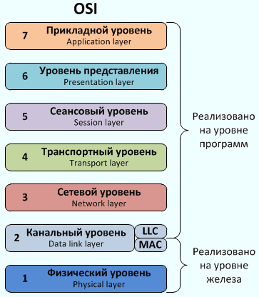
OSI stands for Open System Interconnection. In Ukrainian it sounds like this: Network model of interaction of open systems (reference model). This model can be called a standard. It is this model that manufacturers of network devices follow when developing new products. The OSI network model consists of 7 levels, and it is customary to start counting from the bottom.
Let’s list them:
Application layer (application layer)
Presentation layer or presentation layer
Session layer (session layer)
Transport layer (transport layer)
Network layer (network layer)
Channel layer (data link layer)
Physical layer (physical layer)
As mentioned above, the network model is a model of the interaction of network protocols (standards), each level has its own protocols. Enumerating them is a boring process (and there is no point in it), so it is better to analyze everything on an example, because the assimilation of the material on examples is much higher;)
The application layer is the highest level of the model. It connects user applications with the network. We are all familiar with these programs: browsing the web (HTTP), sending and receiving mail (SMTP, POP3), receiving and receiving files (FTP, TFTP), remote access (Telnet), etc.
Presentation layer – it converts data into the appropriate format. For example, the image you see on your screen (all images) is sent as small pieces (bits) of 1’s and 0’s when you send a file. So if you send a photo to a friend by email, the SMTP application layer protocol sends the photo to a lower layer – presentation level.
There, the photo is converted into a data format convenient for the lower level, for example, into bits (1s and 0s). That way, when your friend starts receiving your photo, it’s sent to them in the same format of 1s and 0s. It is the representation layer that converts the bits into a full-fledged photo, for example, a JPEG. This layer works in this way with such protocols (standards) as images (JPEG, GIF, PNG, TIFF), encoding (ASCII, EBDIC), music and video (MPEG).
Session layer or session layer – as the name suggests, it organizes a communication session between computers. A good example would be audio and video conferencing, at this level it is established which codec will encode the signal, and this codec must be present on both machines. Another example is the SMPP protocol (Short message peer-to-peer protocol), which is used to send well-known SMS and USSD requests. And one last example: PAP (Password Authentication Protocol) is an old protocol for sending a username and password to a server without encryption.
Transport layer (transport layer) – this layer ensures the reliability of transmission from the sender to the recipient. In fact, everything is very simple, for example, you communicate using a webcam with your friend or teacher. Is reliable delivery of every bit of the transmitted image required here? Of course not, if a few bits are lost from the streaming video, you won’t even notice it, even the picture won’t change (for example, the color of one pixel out of 900,000 pixels will change, flashing by at a speed of 24 frames per second).
Now let’s give an example: a friend sends you (for example, by mail) important information or a program in the archive. You download this archive to your computer. This is where 100% reliability is necessary, because if a couple of bits are lost when uploading the archive, you can unarchive it, i.e. extract the necessary data. Or imagine sending a password to a server, and one bit is lost on the way – the password will already lose its appearance and the value will change.
Thus, when we watch videos on the Internet, sometimes we see some artifacts, delays, noises, etc. And when we read text from a web page, the loss (or distortion) of letters is not acceptable, and when we download programs, everything also goes without errors.
At this level, we distinguish two protocols: UDP and TCP. UDP protocol (User Datagram Protocol) transmits data without establishing a connection, does not confirm the delivery of data and repeats. The TCP protocol (Transmission Control Protocol), which establishes a connection before transmission, confirms the delivery of data, repeats it if necessary, guarantees the integrity and correct sequence of the data being downloaded.
So, for music, videos, video conferences and calls, we use UDP (transmit data without verification and without delays), and for text, programs, passwords, archives, etc. – TCP (acknowledgment data transfer, takes longer).
Network layer (network layer) – this layer determines the path by which data will be transmitted. And, by the way, this is the third level of the OSI Network Model, and there are such devices that are called third-level devices – routers. We’ve all heard of an IP address, that’s what the IP (Internet Protocol) does.
An IP address is a logical address on a network. There are quite a lot of protocols at this level, and we will discuss all these protocols in more detail later, in separate articles and examples. Now I will list only a few popular ones. Just as everyone has heard of the IP address and the ping command, the ICMP protocol works. The same routers (with which we will work in the future) use protocols of this level for routing packets (RIP, EIGRP, OSPF).
IEEE (Institute of Electrical and Electronics Engineers) defines the channel layer as two sublayers: LLC and MAC.
LLC – logical link control (Logical Link Control), created for interaction with the upper layer.
MAC – media access control (Media Access Control), designed to interact with the lower layer.
Let’s explain with an example: your computer (laptop, communicator) has a network card (or some other adapter), so there is a driver for interaction with it (with the card). A driver is some program – the upper sub-level of the channel level, through which you can communicate with the lower levels, more precisely with the microprocessor (iron) – the lower sub-level of the channel level.