
07.05.2024
9 min
1133

The third part of a series of articles examines the processes of data encapsulation and decapsulation in the OSI network model. It describes how data passes through the various layers, becoming increasingly detailed, and explains the concept of a PDU to help readers better understand how a network protocol works.

Disclaimer: This article is intended for educational purposes. It explains the process of data encapsulation and the interaction of the OSI and TCP/IP model layers to help readers better understand the principles of information transmission in networks and the construction of modern communication systems.
Encapsulation is the process of transferring data from the upper layer of applications down (through the protocol stack) to the physical layer to be transmitted over the network’s physical medium (twisted pair, optical fiber, Wi-Fi, etc.). Moreover, at each level, different protocols add their own information to the transmitted data. Recall that the OSI network model consists of 7 layers (application layer, performance layer, session layer, transport layer, network layer, channel layer, and physical layer). All network devices work according to the OSI model, only some use all 7 layers and others less. This allows you to process data several times faster.
For example, your computer uses all 7 levels, router – 3 lower levels, switch – only 2 lower levels.
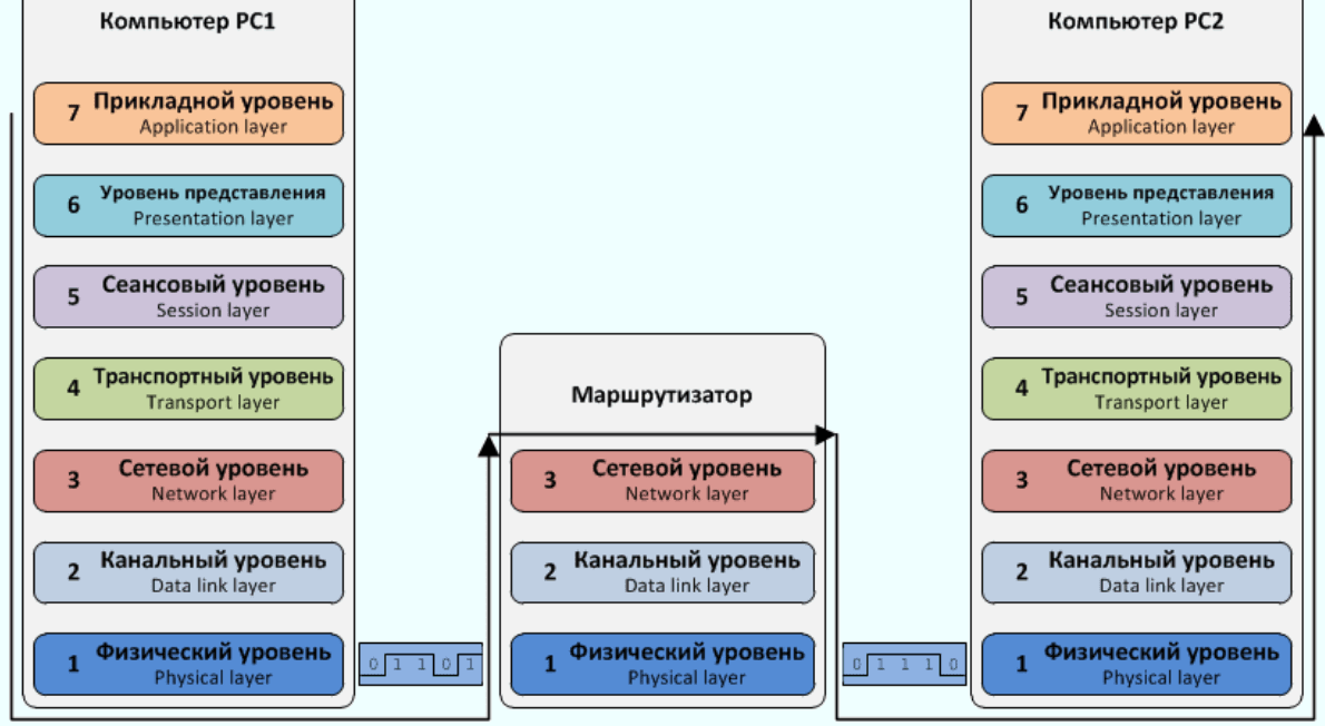
In the picture you see the interaction of two computers between which there is a router. Computers PC1 and PC2 can be both home computers and servers. The router, as mentioned above, works only on three levels of the model, they (three levels) are enough to lay a route in any network. Now let’s move on to the process of encapsulation, decapsulation.
It will be easiest to analyze these encapsulation and decapsulation processes using an example. Let’s say you wanted to view a web page, entered the site address in the address bar of the browser and pressed the Enter button. After that, the browser has to send a request to the server (where this web page is stored) in order to get the data. It is precisely at this stage that the site address entered by you is data that must be transmitted to the server in the form of a request.

This data descends from the application layer to the data presentation layer. At this level, your computer will convert a string of entered text (addresses) into a format convenient for further transmission to a lower level.

Next, the data (no longer text) goes to the session layer, but on it (in this case) we do not need to use protocols (of this layer), so the data is passed on.

The transport layer receives the data and determines what it should be transmitted next using the TCP protocol. Before transmission, the transport layer breaks the data into pieces of data and adds to each piece a header that contains information about the logical ports of the computers (from which the data was sent (for example, 1223) and to which it is destined (in this case, 80)). At the transport layer, these header chunks of data are called segments. Segments are transmitted further down to the network layer.

The network layer, receiving each segment, divides it into even smaller parts and adds its own header to each part. The network layer header specifies the logical network addresses of the sender (your computer) and the recipient (Server).
Logical network addresses are IP addresses known to everyone, it is still not clear what the numbers and dots in them mean, but soon this gap in knowledge will be filled by relevant information 😉
These small pieces of data already with several headers (specific headers are also added at upper layers) are called packets at the network layer, which are transmitted to the channel layer.

At the channel level, packets are divided into even smaller pieces of data, and a trailer is added to them in addition to the added header, only at the channel level. At this level, the headers contain the physical addresses of the transmitting devices and for whom they are intended, and the trailer contains the calculated checksum, a code (information) that is used to determine the integrity of the data.
Physical device addresses are MAC addresses. These very small pieces of data are called frames or frames (one and the same). Next, the footage is transferred to the physical level.

On the physical level, the frames are already transmitted in the form of bit signals and go through other network devices to the destination.

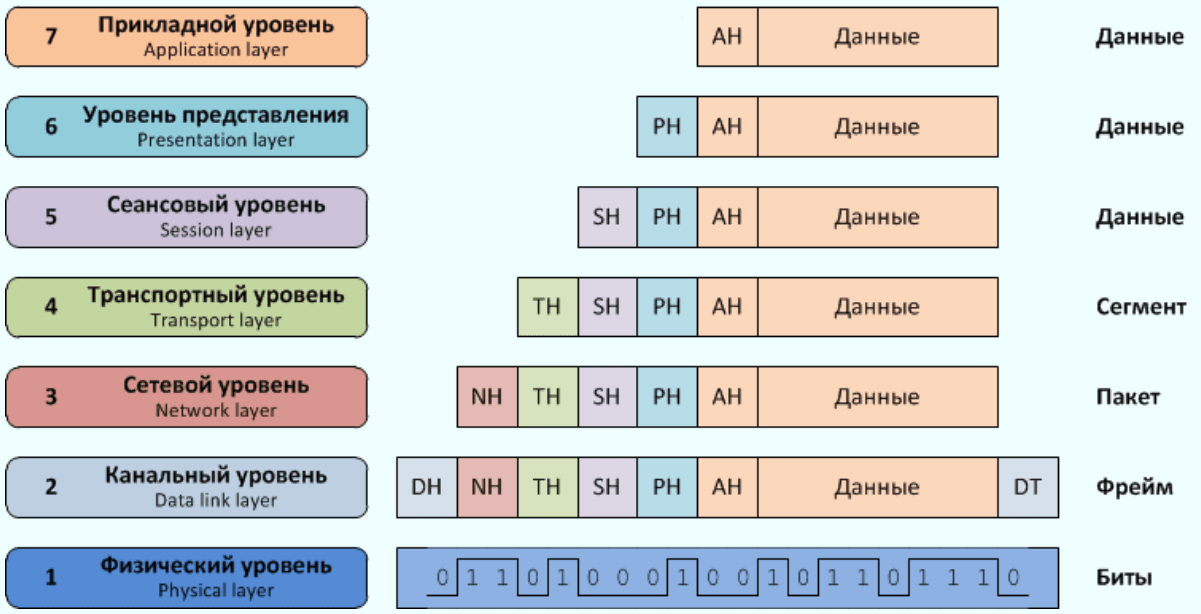
The entire process of converting data (from the upper level) to the signal (to the lower level) is called encapsulation. Take a look at the figure below, it shows the general scheme of encapsulation from the top level to the bottom:
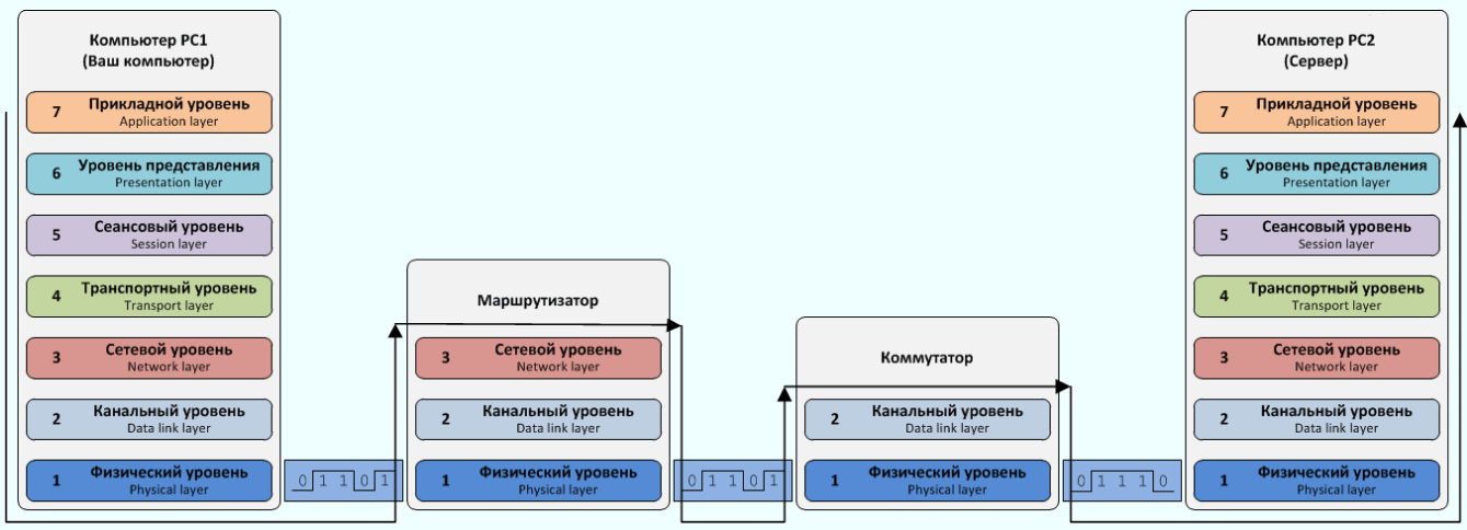
Further, the signals, passing through several network devices (in our case, this is a router and a switch), reach the recipient, in this case, the server (you can click on all the pictures and they will enlarge).
The server NIC takes the bits (physically) and converts them into frames (for the link layer). The link layer in the reverse sequence must convert the frames into packets (for the network layer), only before the conversion, the layer first looks at the MAC address (physical address) of the recipient, it must match the MAC address of the network card, otherwise the frame will be destroyed. Then the channel layer (if the MAC address matches) calculates the sum of the received data and compares the received value with the trailer value. Let me remind you that the value of the trailer was calculated on your computer, and now, after being transmitted over the wires, it is compared with the received value on the server, and if they match, the frame is converted into a packet. If the data integrity check code is different, the frame is immediately destroyed.
At the network level, the logical address (IP address) is checked, if the check is successful, the packet is converted into a segment, reaching the transport layer.
At the transport level, the information from the header is checked, what kind of segment it is, what protocol is used, for which logical port is assigned, etc. The protocol used was TCP, so a segment arrival message is sent to your computer. As mentioned above (when the data was packed into a segment), in that case the destination port 80 was used. Because As soon as this port is open on the web server, the data is transmitted further to the upper level.
At the upper levels, the request (entered site address) is processed by the web server (checking whether the requested web page is available).
This process of converting signals from the wire into data is called the decapsulation process.
Once the page is found on the server, it (text, image, music) is converted into a digital code suitable for encapsulation. A large amount of data is divided into parts and sent to a lower level – transport. There, the piece of data is converted into a segment, only the destination port will now be the one you sent from (remember, 1223). The segment is converted into a packet, the header of which contains the IP address of your computer and goes below. At the channel level, the packet is in turn converted into frames and a title and trailer are added. The header contains the MAC address of the destination (in this case, it will be the address of the gateway), and the trailer contains the data integrity check code. Next, the network card sends frames in the form of signals via a cable in the direction of your computer.
This is how network data exchange, encapsulation and decapsulation takes place.
You got acquainted with the reference network models OSI, TCP/IP (DOD), understood the processes of encapsulation (encapsulation) and decapsulation (decapsulation). It was also found that different network devices work at different levels.