
29.01.2025
3 min
820

Learn how to make your own automatic landing gear for quadcopters like the WLtoys Q333A and DJI Inspire using an Arduino NANO board. In our step-by-step guide, we’ll show you how to set up a system that automatically raises and lowers the landing gear when it reaches a certain height.

One of the users has a quadcopter with a movable landing gear, which is controlled by buttons on the remote control. It is necessary to set up a system that will automatically raise and lower the landing gear when it reaches a given height, for example, 1.5 meters.
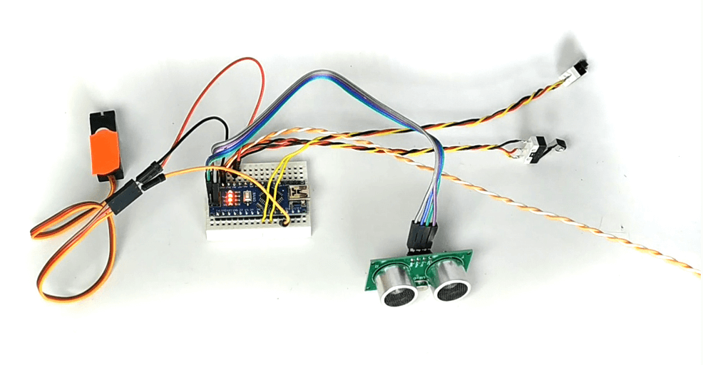
This is what the automatic drive mechanism for the landing gear that needs to be installed on the quadcopter looks like.
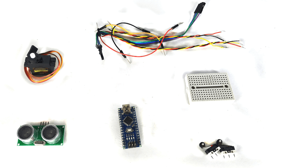
For assembly you will need:
Arduino NANO board;
Ultrasonic position sensor HC-SR04;
Two terminal blocks;
Connecting wires;
Breadboard and 360-degree servo motor.
First, you need to load a sketch that has only one setting.
The main parameter is the cm variable, which defines the height in centimeters. By default, its value is set to 10, but you can change it to suit your needs.
Since the maximum measurement range of the HC-SR04 ultrasonic sensor is 400 cm, it is recommended to set the value to no more than 380 cm. Too low values are also undesirable, as the landing gear must have enough time to unfold during landing.
#include "Servo.h"
Servo myservo;
#define trigPin 13
#define echoPin 12
int sm = 10; //расстояние в сантиметрах, для срабатывания шасси (максимум 380 см)

void setup() {
  Serial.begin (9600); myservo.attach(9);
  pinMode(trigPin, OUTPUT); pinMode(echoPin, INPUT);
}

void loop() {
  long duration, distance;
  digitalWrite(trigPin, LOW); delayMicroseconds(5);
  digitalWrite(trigPin, HIGH); delayMicroseconds(10);
  digitalWrite(trigPin, LOW);
  duration = pulseIn(echoPin, HIGH);
  distance = (duration / 2) / 29.1; // Результат в сантиметрах в переменной distance
  Serial.println(distance);
  int button6 = digitalRead(6);
  int button7 = digitalRead(7);
  if ((distance > sm) && (button7 == HIGH)) {
    myservo.write(0); //отправка шасси в низ
  }
  if ((distance < sm) && (button6 == HIGH)) {
    myservo.write(180); //отправка шасси в верх
  }
  if (((distance > sm) && (button6 == HIGH)) || ((distance < sm) && (button7 == HIGH)))
  {
    myservo.write(90); //остановка шасси
  }
}
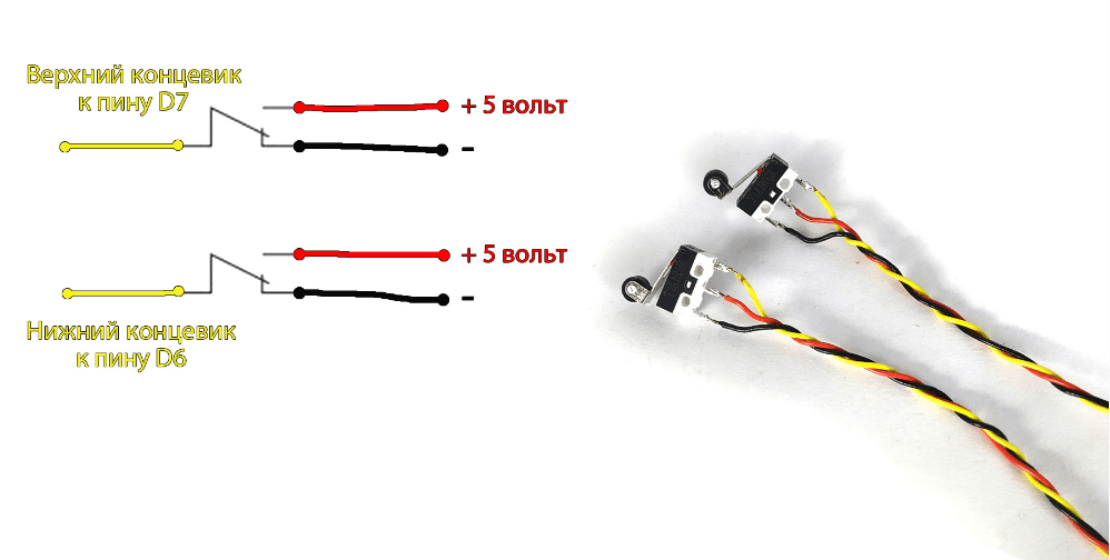
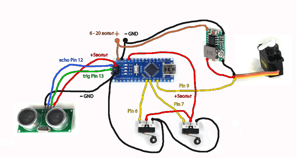
After loading the sketch, solder the wires to the terminals according to this diagram.
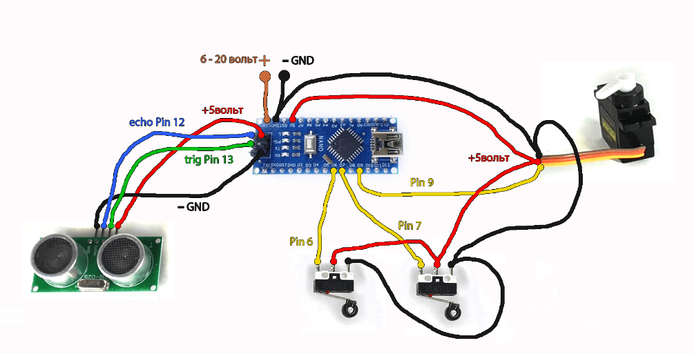
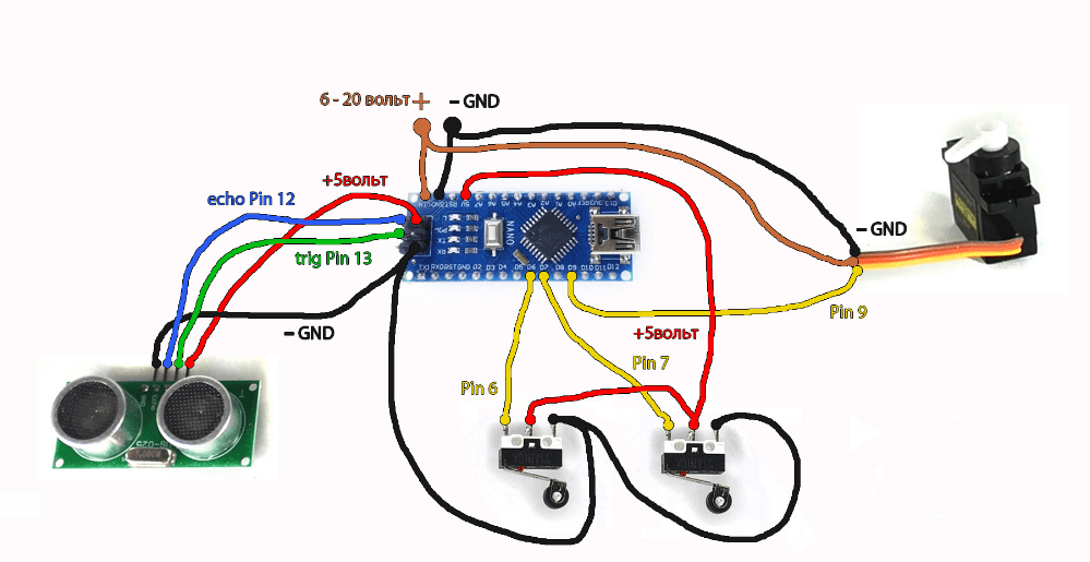
Next, you need to assemble all the components according to one of the three schemes, choosing the one that best suits your configuration.
If you are using a servo motor that operates from 5 volts and consumes up to 500 mA, it can be powered directly from the Arduino NANO board. This is implemented according to the scheme where the servo motor is connected to the power output of the board, which ensures stable operation of the system.
If the servo motor’s supply voltage matches the voltage of the battery used, it can be connected directly to the battery.
If everything is connected correctly, you can apply power and check the landing gear. First, test raising it to a height higher than that specified in the variable cm.
It is important that the ultrasonic sensor HC-SR04 is directed downwards, as it measures the distance to the surface of the landing site. This will ensure correct operation of the automatic mechanism.
Link to video instructions: https://www.youtube.com/watch?v=IkO81w7DcTA&ab_channel=MasterKolotushkinArduino