26.08.2024
2 min
1254

How to Build Your Arduino Board: A Step-by-Step Guide to Using Microcontrollers, Circuits, and Bootloaders Step-by-step process from chip selection to board assembly. Tips for layout, programming and project optimization.
Today, there are many options for Arduino boards, which are popular due to the use of the Wiring framework, a wide selection of shields and the ability to conveniently download programs via USB. Most of the boards are printed circuit boards with the minimum necessary components for microcircuits, which makes it much easier to work with them. However, for some controllers ready-made solutions may not exist or they may be universal, which leads to the appearance of inaccuracies. This causes the need to develop its own evaluation board for a domestic chip.
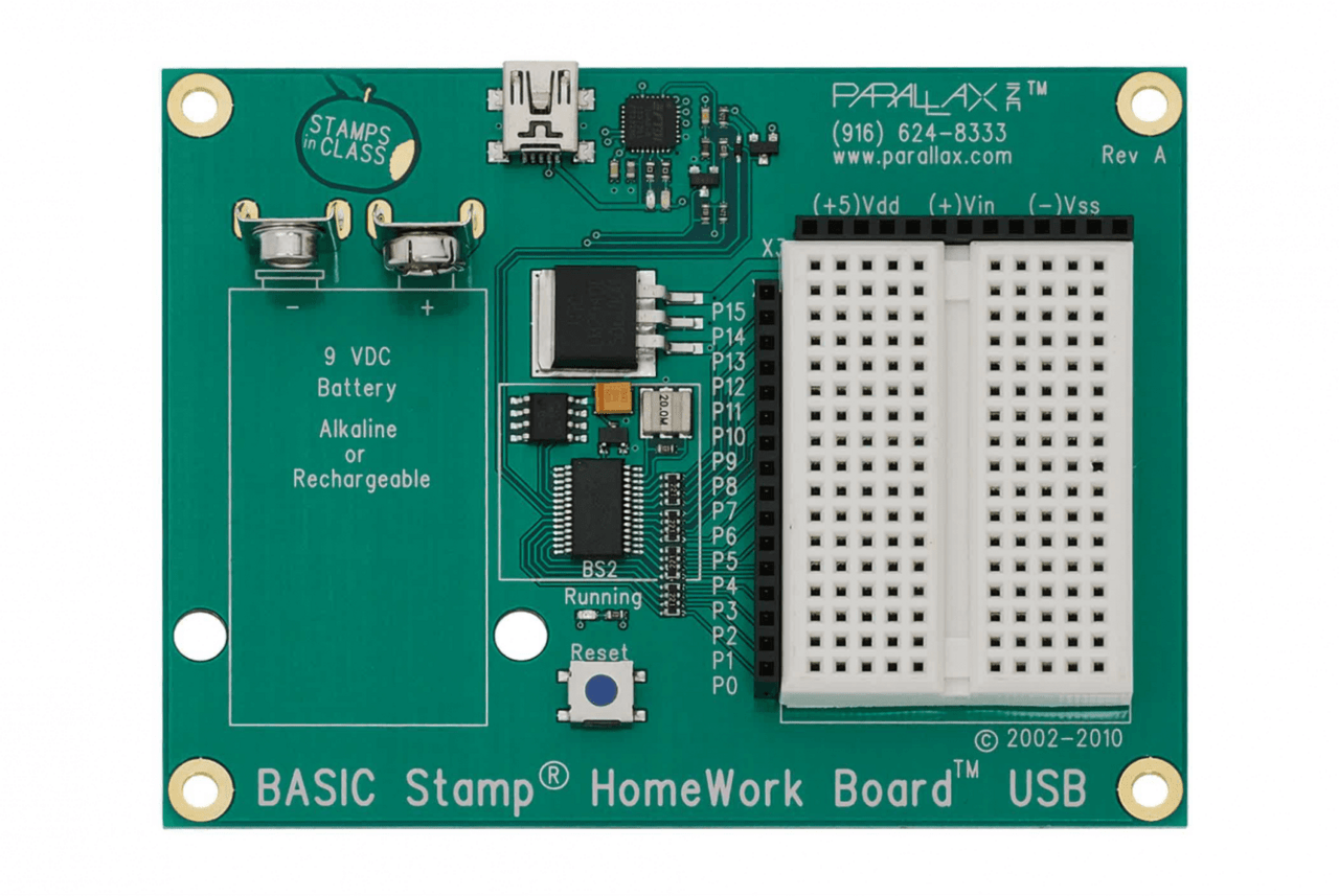
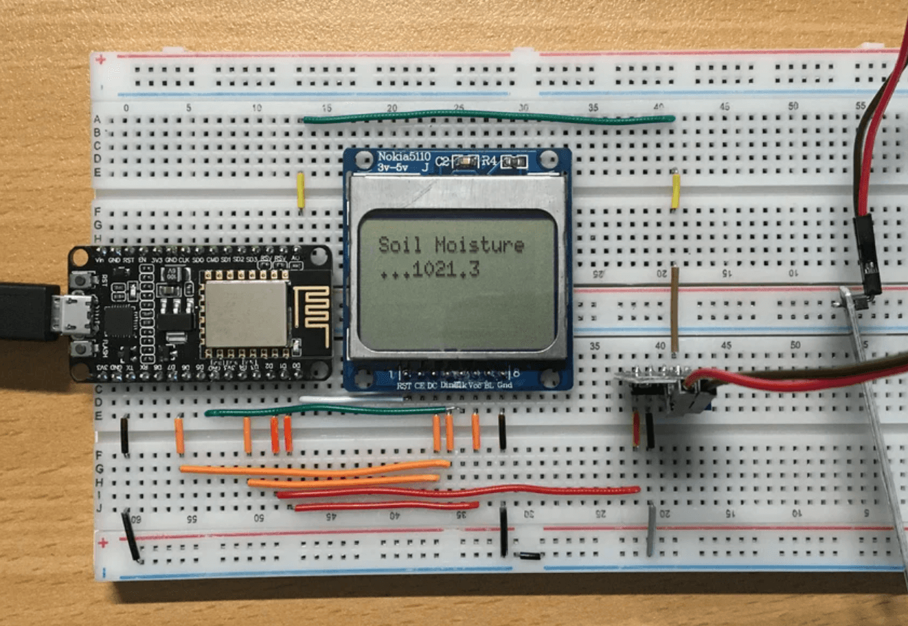
One of the first prototyping boards is the Basic Stamp, which is mentioned in the classic electronics literature. It includes a power supply circuit, a USB-UART (formerly DB9) interface converter, a chip socket or soldered controller, as well as a breadboard and PLC connectors. A similar alternative is the ESP8266-based board, which is also used for mock-up and prototyping.
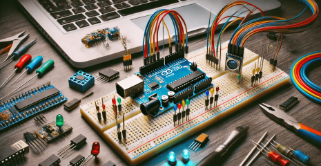
Arduino boards have become widespread, in particular due to the use of “shields” – expansion boards that are installed on the connectors on top. These boards usually implement one or two functions, take up a lot of space, but their convenience lies in educational purposes and the ability to test circuits and hypotheses. One of the first and most popular models was the Arduino Uno, which became the basis for further developments in this area.

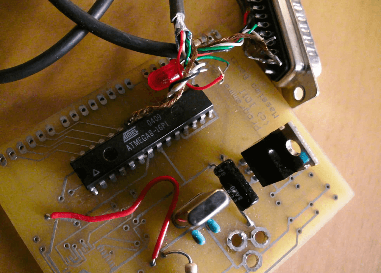
Fun fact: the first Arduino was made as a competitor to the Basic Stamp and connected to a PC via a DB25 COM port. Today, the COM port has become virtual, but software is still downloaded through it.
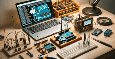
Later, a more convenient board was released – Arduino Nano. Its compact form factor allows you to easily place it on a breadboard, which greatly simplifies the drawing of circuits and makes the work more visual. Similarly, you can install ESP8266 or ESP32, which appeared later and are also suitable for mock-up and prototyping due to their similar design.
It was decided to choose an Arduino Nano board, adapting it to a specific controller. The established technical requirements included key parameters for the optimal operation of the board, ensuring the necessary compatibility and efficiency in the implementation of the project.
using the K1946 controller or compatible AVRs,
the presence of a USB-UART interface converter with a reset signal (DTR);
form factor – a printed circuit board with a width of up to 30 mm and a length of up to 50 mm;
two rows of pin connectors with a pitch of 2.54, micro-USB for updating.
The choice of micro-USB is dictated by practicality, because for a board used for debugging and prototyping, it is easier to resolder it in case of damage. The wide legs of micro-USB are better suited for such tasks than the thin type-C contacts. In addition, wires with such a connector are available in many stores. K1946 was chosen as a microcontroller because it is a domestic analogue of popular samples, for which there are already developed libraries and environments that facilitate experimentation and work.
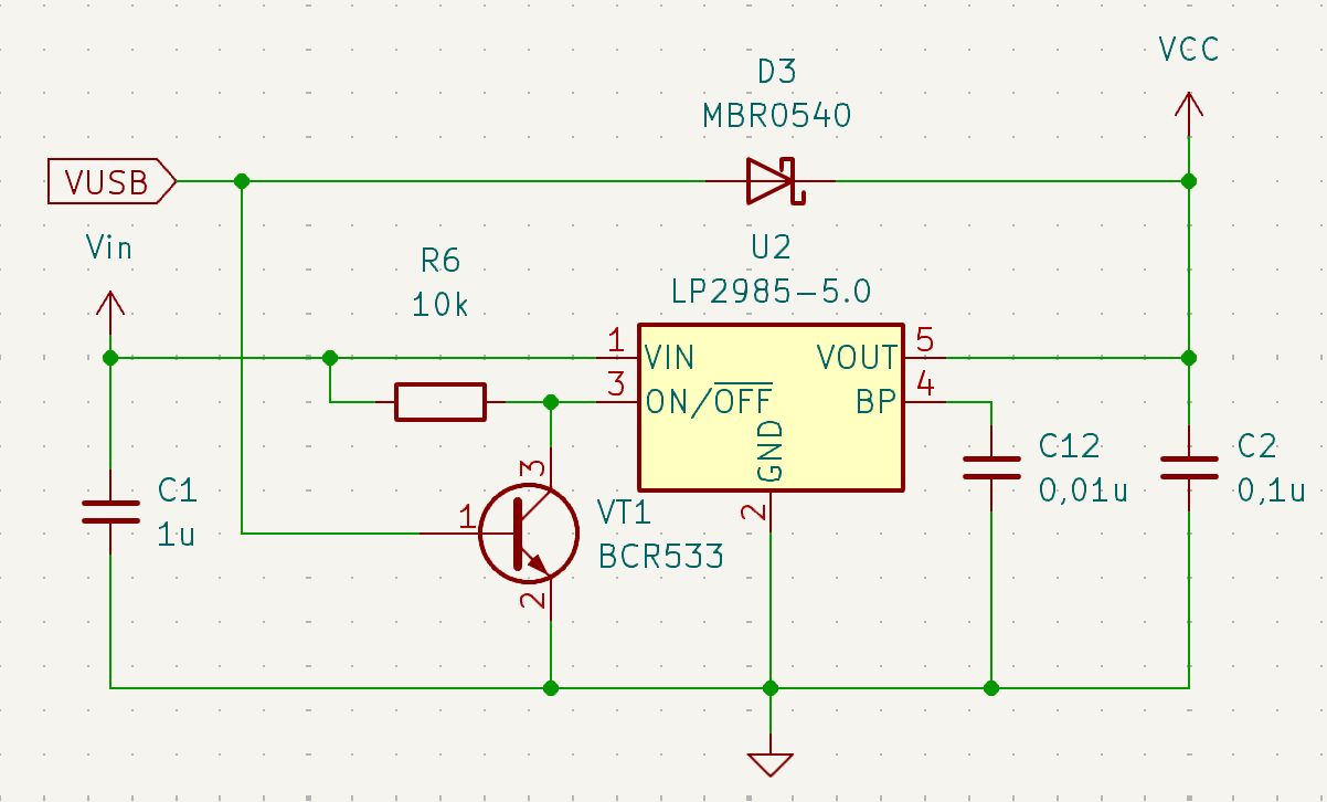
In the creation of the board, publicly available codes, schemes and materials distributed in documentation and articles were used. The main difference is the presence of capacitors at the inputs of the microcontroller, which improves the stability of operation compared to Chinese counterparts. In addition, an LP2985 regulator is used, which provides higher load current, less voltage drop and has a disconnect function that allows USB connection without disconnecting the external power supply.
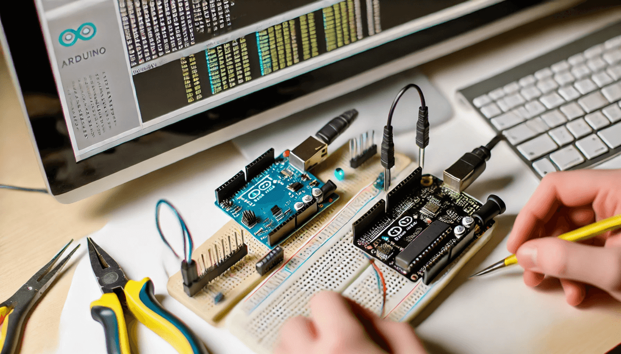
The board project was aimed at creating the most compatible version with the Arduino Nano. Three connectors were added for the microcontroller’s C port to use all the chip pins that were routed to a breakaway part of the board. This design allows you to remove an unnecessary part for installation in “signs”. The idea is borrowed from STM8-Discovery from STMicroelectronics, which allows you to flexibly adapt the board to different needs.
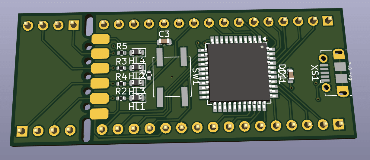
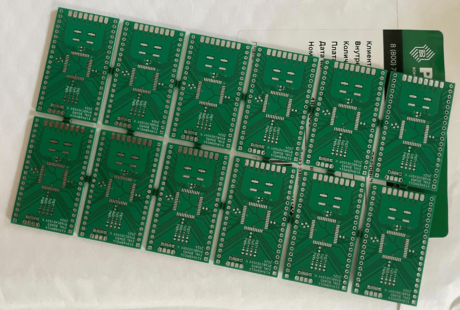
In the process of experiments, it was decided to move away from the standard Arduino Nano form factor and make the board wider, which makes it easier to place it on a large breadboard. Left the idea of a port on one of the ends, adding two analog inputs and a UART interface for expansion. After research and testing was completed, a batch of green boards was ordered for further testing.
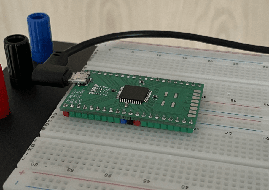
The dimensions of the resulting products are placed on a large mock-up, leaving enough space for connecting components. I prefer to use an angled cable with a micro-USB: in this configuration it is quite convenient and does not interfere.
The presence of a boot record on the chip, even with the presence of a programmer, provides convenience during debugging and updating. Through the serial interface, you can set up communication with the software on the PC, and also easily output debugging information. This allows you to update software in ready-made devices via USB without the need for additional tools or opening the case. Downloading updates in this way does not require special knowledge, which makes the process as convenient and accessible as possible.
I chose optiboot as the boot entry. It has sufficient functionality, is actively supported by the community in the official repository on GitHub and weighs little. Bootloaders for other evaluation boards were originally built on the basis of this project. By the way, the GyverCore core works more efficiently on optiboot.
So, first you need to prepare the OS for collecting files. You will need avr-gcc, preferably the latest version.
Installation on Ubuntu is the easiest and is described in the tutorial.
macOS will require brew and install the package (found on GitHub).
Installation on Winows is a little more complicated than on Linux, but the step-by-step guide will help you.
An alternative option for Windows is avr-gcc as part of the arduino ide.
For compilation, it is enough to download the repository and follow the instructions from the project wiki on GitHub to collect the source files and download the binary code. You need git on your PC to download. Or you can download the archive:
git clone https://github.com/Optiboot/optiboot.git
cd optiboot/optiboot/bootloaders/optiboot
Next, we perform assembly. The OS must be specified for the script to tweak some variables and fix path symbols (on Windows).
make OS=macos \
UART=0 BAUD_RATE=115200 \
LED=B7 LED_DATA_FLASH=1 \
AVR_FREQ=16000000L atmega8535
During compilation, make will issue warning lines:
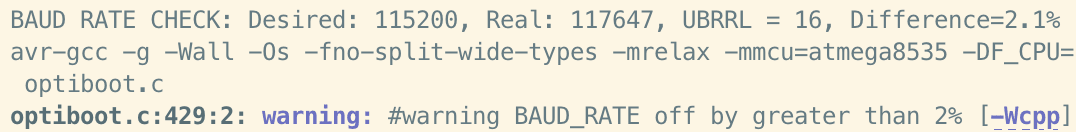
A 2% error isn’t terrible, but you’ve been warned. To avoid this, you can change the resonator frequency or the interface speed.
With the last command, we will load the formed bootloader into the board. For this I use avrdude:
avrdude -P usb -c usbasp -p ATmega8535 -s -B 16kHz -U flash:w:optiboot_atmega8535_UART0_115200_16000000L.hex
For further use from the console, we take this line and replace the fields with our own:
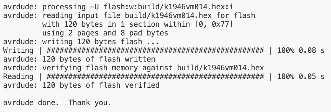
avrdude -p m8535 -c arduino -P /dev/tty.usbserial-0001 -b 115200 -U flash:w:build/k1946vm014.hex
A few lines were added to the makefile to make changes:
pusb: $(TARGET).hex
avrdude -p $(DUDE_MCU) -c arduino -P $(PORT) -B $(PORTSPEED) -U flash:w:$(BUILD_DIR)/$(TARGET).hex
At this stage, the main task is completed. The board is detected and updated via USB with VSCode:
The received boards are successfully used for debugging, but during the work it was found that some elements are missing for greater convenience. This allows you to optimize them for further use and improve existing solutions.
For example, it was worth adding:
stabilizer 3.3 – some microcircuits or indicators work from this voltage;
reference voltage source (the same tl431);
unlocking the “reboot” signal of the controller from ch340 (this issue was temporarily solved by changing the bootloader and cutting the track).
The main functionality of the board, including bootloader, microcontroller and interface converter, is fully used. During the operation of the board in the layout, the developer can connect to remove logs, change modes or update the firmware. A case with a firmware update was checked, where a non-specialist was able to successfully complete the work thanks to the prepared bat-script and hex-file of the firmware, which greatly facilitated the process.
If you have any problems, you can contact us at [email protected].