19.08.2025
30 min
945

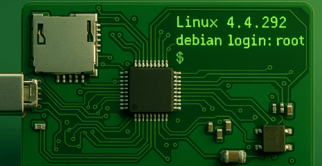
In the second part, we delve into the technical details of LinuxCard — a business card that runs Linux. The author explains how its own bootloader works without a traditional PROM, how the minimum set of services for starting the kernel is implemented, and why the SD card is used as the main storage. Optimizations of the uMIPS emulator, creation of a paravirtualized disk driver, instruction caching, and multi-level access to RAM are discussed in detail. Patches to the Linux 4.4.292 kernel that reduce its size and speed up work are also described, as well as experiments with running Ultrix and even NetBSD. LinuxCard proves that from the ATSAMD21 microcontroller and several memory chips, you can build a unique platform capable of running multiple OSes in the format of a pocket project.
Usually at physical address 0x1fc00000 there is a 256KB embedded ROM (which DEC calls a PROM) that contains enough code to display messages on the screen and accept keyboard input, communicate with SCSI devices, load files from disk to RAM, and access them. This PROM also provides many services to the booted operating system through an array of callbacks. This includes things like console logging, EEPROM-supported environment variables, memory mapping information, and so on. This is quite similar to UEFI. Normally this PROM reads environment variables from the EEPROM that tell it which device to boot from, and then loads the kernel and boots from that device if all goes well. This emulator does not boot in this way.
I didn’t want to include a large ROM in the emulator, as the amount of flash memory in the microcontroller is limited. I also don’t have a graphical console or keyboard per se. Given this, I had to somehow implement a significant subset of the ROM, since MIPS Linux uses it. What to do? I decided to come up with my own boot process, which can still work just as well. The ROM is indeed at address 0x1fc00000 . This is necessary for rebooting from Linux. Its source code is in the “romboot” directory. It loads the first sector of the SD card to the beginning of RAM at address 0x80000000 and jumps to it. The first sector of the SD card contains a standard MBR partition table and up to 446 bytes of code. The code that is located here can be found in the “mbrboot” directory. It is also quite simple. It looks in the partition table for a partition with byte type 0xBB. If not found, an error is displayed. Otherwise, the partition is read entirely into RAM at address 0x80001000 and then jumps to it. This partition can be arbitrarily large, and that is where my “PROM” implementation resides. Its actual size limit is set by the fact that MIPS Linux expects to boot at address 0x80040000. This is no coincidence – the first 192 KB of RAM are reserved for use by the PROM while the operating system expects to use PROM services. Thus, the size limit for the loader is 188 KB.
The code for my PROM implementation can be found in the “loader” directory. It will look on the SD card for a partition marked as active, attempt to mount it as FAT12/16/32, and look for a file called “VMLINUX” in the root directory. If found, it will be parsed as an ELF file, properly loaded, and run. Otherwise, an error will be displayed. Since this code has no serious size limits, it implements proper console logging, printf, and all sorts of other conveniences. As for the PROM services, they provide console logging, memory mapping information, and reading environment variables, at least enough to keep Linux happy. I haven’t tried booting other operating systems on uMIPS (yet?).
The kernel command line I pass is pretty simple: earlyprintk=prom0 console=ttyS3 root=/dev/pvd3 rootfstype=ext4 rw init=/bin/sh . The first parameter provides early boot logging via the console PROM, which is nice to see. Once the kernel is up and running, it will use the third serial port for the console. Originally for the DECstation it was a serial printer port, but Linux users on DECstations use it for a serial console because it is the easiest port to convert to a simple serial port. The rest is just telling the kernel how to boot. I prefer to boot into sh and then do exec init myself, like this init=/bin/sh
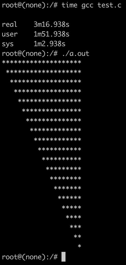
After all the optimizations (which I will explain in detail later), the effective speed of my virtual MIPS R2000/R3000 on this ATSAMD21 hellish chip is about 1.2 MHz. The processor spends about 8% of its time processing timer interrupts, so about 1.06 MIPS of processor cycles are left for useful work. With this, the kernel takes about 2 minutes to boot and run sh . Running init busybox and getting to the login prompt takes another minute. Overall, not bad. Commands respond instantly or within a few seconds. Compiling a C program “hello world” with gcc takes about 2 minutes, and I estimate that in a few days I could rebuild the kernel on the device itself, copy it to /boot, and reboot.
The emulated real-time clock actually shows the real time, plus or minus the inaccuracy of the ATSAMD21 ultra-low-power 32 kHz timer. This is normal enough that you won’t notice it. Try the uptime command.
There’s only one thing I haven’t discussed yet about running Linux on uMIPS. It’s memory. I said it was an SD card, but the DECstation definitely doesn’t have an SD card slot. Linux, however, is open source. I just wrote my own very simple paravirtualized disk driver that uses a hypercall to communicate directly with the emulator and requests sectors to read or write directly to the virtual RAM. For Linux, this looks just like DMA, only instantaneously. The entire driver implementation is less than 200 lines of code and can be seen in pvd.patch.
I made some changes to the kernel to make life easier. They are provided as patches for kernel 4.4.292, as well as a working kernel image. Why this version? Because when I started this project, it was an LTS kernel, and since RAM was tight, I wanted to have the smallest kernel possible, so this was better than a later version. The configuration I use is available in kernel_4.4.292.config . The configuration for an even smaller kernel (which requires uMIPS to emulate a full FPU) is available in kernel_4.4.292.config_nofpu.
I have put a lot of effort into making the kernel as small as possible. Since Linux does not support paging kernel fragments, every byte of kernel code becomes one byte smaller, available for use in user space. I have ruthlessly removed unnecessary options. In the end, I managed to reduce the kernel size to just under 4MB, which is pretty good considering that MIPS instructions are not very dense.
As part of this work, I made a few code patches. For various reasons (hmm… latency slots… hmm) the kernel might need to interpret user space code or parse user space instructions. No matter what kernel configurations I provided, the code to handle microMIPS (a future MIPS extension, unknown at the time of the R2000/R3000) was present. This was wasting space and time trying to handle things that would never happen. The useless_exc_code.patch patch removes this code if the target processor does not support microMIPS.
Before I implemented my FPU emulator, I was using the kernel’s FPU emulation code, which intercepts and executes FPU instructions. It had a bug. When compiled for a 32-bit MIPS processor, it incorrectly emulated some FPU instructions that operate on doubles. I believe this is incorrect. This caused code compiled for the R3000 to crash. The fpu.patch patch modifies the kernel’s MIPS FPU emulator, adding a configuration option to enable full FPU emulation even on MIPS-I chips.
Due to the differences between the R2000/R3000 and R4000, the kernel needs to know at build time which processor it is compiling for. If you try to run the wrong kernel type on the wrong processor type, it will just make you panic. Okay, fine, but then why doesn’t this flag affect a significant portion of the TLB handling code? Both types always compile, even though we know at build time with 100% certainty that at least half of them will never be useful? The tlbex_shrinkify.patch wraps unnecessary code with checks for the processor type selected at compile time, thus removing some kernel code, saving valuable bytes.
Since uMIPS runs on a true real-time clock, I didn’t want Linux to spend too much time handling timer interrupts. DECstations typically use a 128 Hz timer on Linux. I also added options for 64 Hz, 32 Hz, and 16 Hz timer cycles. This reduces the effective resolution of the timer, but effectively frees the virtual processor from having to spend most of its time handling timer interrupts. The clocksrc.patch patch does this, and the one called kill_clocksrc_warning.patch silences the silly timer resolution warning.
If you are compiling uMIPS with full FPU emulation, there is also a patch to remove all FPU emulation code from the kernel to save a few KB of RAM: fpu.patch.
One of the things that the processor will definitely do every cycle is fetch an instruction. This means that every cycle starts with a memory access. This is a pain point for us because of the Atmel SPI block that has bugs. Not only that, but there is also a memory translation that needs to happen, which takes time. A good way to avoid both of these problems is the VIVT instruction cache. It will read instructions 32 bytes at a time and hopefully won’t need to do address translations or access main memory very often. I’ve allocated 2KB of RAM for this cache. That’s 32 sets of 2-lane lines of 32 bytes each. Whenever the memory mappings change, they need to be invalidated. I do this automatically, so the code running on the MIPS virtual processor doesn’t have to know about it. The measured hit rate during Linux boot is about 95%, which is pretty good for such a small cache. The geometry was determined experimentally by profiling load times with different cache geometries. This was found to be the best.
The ATSAMD21 series is designed to run at 48 MHz. In my testing, they run fine up to 96 MHz, with some individual chips capable of reaching 110 MHz. I didn’t find any chips to be unstable at 96 MHz, so I decided to just run at 90 MHz for some safety margin. This gave me a pretty big performance boost right away. No, it’s not quite 100%, because (1) the SPI RAM is still limited by the SPI speed limit, and (2) the flash has wait states that had to be increased for the higher speed. But it gave me a fair 65% improvement. Still a good start. The SPI RAM is now running at CPU/6 = 15 MHz.
Since I couldn’t speed up the SPI RAM blocks due to Atmel’s incompetence, I decided to expand it! I can manage four blocks at once. Considering that each read and write command requires additional overhead, it’s still faster than one or two. Quite an apt statement, isn’t it? This microcontroller has quad-channel RAM! The emulator accesses the RAM in 32-byte increments. The RAM read/write commands themselves are 4 bytes each. This means that for a single-chip RAM situation, reading 32 bytes takes (4 + 32) * 8 = 288 SPI bits. In a dual-channel configuration, you would need (4 + 16) * 8 = 160 SPI bits, since the instruction is still 4 bytes long, but we are only reading 16 bytes from each RAM, for a total of 32. For quad-channel RAM, we have (4 + 8) * 8 = 96 SPI bits to read 32 bytes. That’s a 66% improvement over single-channel! In reality, the improvement is less, since quad-channel mode can’t use DMA at all, so it’s a bit slower. Real-world measurements show that quad-channel mode is a 50% improvement over single-channel. But still, given this damn chip, any improvement is an improvement I’ll accept.
But why are all RAM accesses 32 bytes long? Well, as you can see, RAM accesses are slow. A typical 32-byte access takes about 140 SPI cycles, which is about 12 microseconds. If each access took that long, my emulated processor would be limited to no more than 85,000 memory accesses per second. That’s too slow to be practical. Something had to be done. I decided to use a cache. Unfortunately, my microcontroller has a very limited amount of RAM, so the cache had to be small. I evaluated different cache geometries and found that a 20-channel, two-way cache with 32-byte lines provided the best performance boost for the emulator. It gets 91% hits during kernel loading, which is pretty good for 1.25 KB of RAM. With a hit taking about half a microsecond and a miss taking about 12 microseconds, adding this cache improved the average memory access by 87%! Yes, that’s actually L2 cache. How many emulators do you know that have L2 cache to hide the terrible performance of their chosen hardware? The cache allocates memory for reads and writes, except for reads and writes of exactly 32 bytes. These are passed directly, as they are either DMA to access the SD card or icache fetches, which don’t need to be cached in that cache either.
After some additional profiling, I rewrote the “hot” part of the memory access code in assembler for even more speedup. GCC may have come a long way since the last decade, but it still can’t match handwritten assembler. I removed support for single and dual channel RAM to also simplify the “hot path”. So now you need to fill all four RAM slots to boot the card. If you fill different sizes of RAM, the smallest of them will dictate the final usable RAM size. The usable RAM size will always be four times the size of the smallest RAM chip. This is not a big deal, the DECstation came with 4MB of RAM and could be equipped with a maximum of 24MB. This card can be equipped with 32MB, so you will live like a king! That being said, due to the size of the Linux kernel, you will not get a successful Linux boot unless you have at least 6MB of RAM.
Did I also mention that because of the way delay slots work, if the CPU throws an exception for an instruction in a delay slot, the kernel should be able to fully emulate that instruction or otherwise execute it and then jump to the right place? Linux takes advantage of the fact that MIPS has no PC-related instructions other than jumps, and placing a jump in a delay slot is forbidden. How? Instead of emulating the delay slot instruction, Linux copies it to a special page in memory, followed by a trap. Linux then jumps there in user mode to let it execute, catches the trap, and then redirects execution to where it needs to go. Now, if that sounds like a huge hassle to you, you’re right. What can we do? Well, if the instruction in the delay slot actually throws an exception (like an illegal access, or a TLB refill exception, or something like that), there’s not much we can do. But what we CAN do is not make things worse. uMIPS will not deliver the IRQ before the instruction in the branch delay slot executes. In the worst case, it will delay the IRQ for one cycle, which does not affect correctness. The advantage is that such copying and juggling of instructions can be done less frequently.
Now, why did you actually come here? How can you get one? Well, you can try to meet me in person and ask for my business card, I have a few I can give away, but other than that, here’s how to do it.
You will need to order the board from a PCB manufacturer. I’m a fan of JLPCB and recommend them. The Gerber files I provide come in two versions. One is exactly as you see my card, and the other without my name and contact information :). It’s a four-layer board, the PCB manufacturer will ask you for the order of the layers, which is: GTL, G1, G2, GBL. At least JLPCB has the options of gold plating the edge connector for better contact, called “gold fingers”, and grinding the edge of the board to 45° for easier insertion. I suggest choosing both of these options – they’re free. Don’t forget to set the board thickness to 0.8mm.
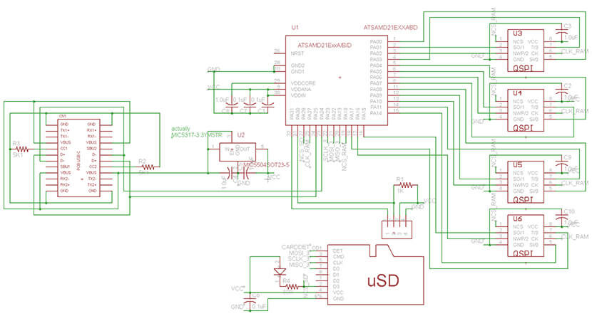
While you are waiting for the board to arrive, you will need to order the parts. You will need four identical memory chips (links are above), an ATSAMDA1E16, an AMPHENOL 11400841 SD card slot, and a MIC5317-3.3YM5TR regulator. You will also need (optionally) to order a blue or white 0603 size LED for the SD card activity indicator. If you choose this LED, you will also need a 430 ohm 0603 or 0805 size resistor. In addition, you will need: 2 x 5.1k resistors, 1 x 1k resistor, 3 x 0.1uF capacitors, and 7 x 1.0uF capacitors. You will also need an SD card and any SWD programmer capable of programming the ATSAMD chip. There are many of them. Choose your favorite.
You will also need an SD card. 128MB is the absolute minimum if you want to host a busybox based rootfs. To host a debian or hybrid image like I provided, you will need at least 512MB. You can burn the image to the card using your favorite tool for this. On Linux and MacOS, this is probably dd, on Windows, it is Win32DiskImager.
Once you have assembled the board, program the microcontroller using the provided binary /emu/uMIPS.bin, and you are done!
You will need to compile a few things. You will need both ARM (CodeSourcery) and MIPS GCC toolchain (I used mips-mti-linux which I found online). First compile “romboot”, “mbrboot” and “loader”. Then compile the kernel. I have provided the configuration, patches etc. Then you will need to compile the emulator. To compile for MCU use (UPDATE: the actual target name has changed, see update later in the article). To compile for PC try make CPU=pc . Then you can compile the SD card image. You will need to copy the MBR from one of mine and modify it, then use mkdisk.sh to embed your kernel, mbrboot and bootloader. Use a loop mount to copy to your rootfs.
If you want to run the emulator on PC there are a few things to consider. First, Ctrl^C will kill it :). Second, unlike the MCU version, the PC version does not include a bootloader ROM in the binary, so you will need to point to it on the command line. A typical command line is ./uMIPS ../romboot/loader.bin ../disk.wheezy
For the lazy, I am trying to sell all the parts and the board together as a kit on tindie. I will see how it goes. I suspect that will be a huge tedious task and not worth the time, but I am giving it a chance. EDIT: Obviously not, and not even for a good reason. Quote: Please resubmit for admin approval once you specify: Other reason. . LOL, how about NO? By the way, if anyone knows of any companies that do similar things for me (selling a kit I designed), please email me. If you’re really lazy, I might also consider putting together a batch of these kits at the factory at JLPCB. If you’re interested, click here and let me know. No promises yet.
I’m providing a couple of disk images. The smallest one is a busybox-based image (disk.busybox) – it’s small, fast, and cool. I built busybox from source for MIPS-I with as many applets enabled as I could imagine. The second image is a full rootfs from debian wheezy (the latest version with MIPS-I support). I should warn you that debian “init” starts about 3000 processes on boot, so it takes a long time. If you are using the debian disk image (disk.wheezy), I strongly recommend just mounting proc and sys, and doing your stuff in “sh” without running “init”, but it will work if you do that… eventually. I also provide a hybrid image (disk.hybrid). It has the busybox and init shell, but contains all the debian binaries, so things not provided by busybox are still there and working, like gcc and vim. It is a “hybrid” image.
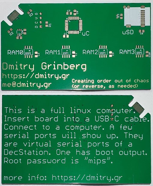
Using the LinuxCard is very easy: insert the SD card, connect the USB-C to your computer, and open your favorite serial port console program (minicom, PuTTY, etc.). If the boot log doesn’t show up, try a different virtual serial port (there are two). In case of a boot error, the SD card LED will blink endlessly, you can look at the code for details on what the different number of blinks mean.
Once you see the shell prompt, you can experiment or continue booting to login by typing exec init . After that, you will be able to login as “root” with the password “mipsmips”. You will also see a login prompt on the second serial port. So cool!
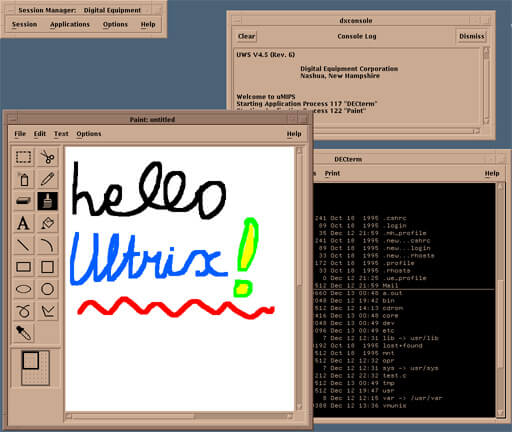
Ultrix is the current UNIX version for the DECstation2100/3100. The latest version is 4.5, and with some Google searches you can find ISO images of the installation media. It supports the DECstation2100/3100 perfectly and even has an X11 based user interface! The goal of the v2 firmware was to get Ultrix working properly on the card. In the end, it took a lot of work. I had to improve the emulation accuracy and implement more hardware. But it worked!
My first attempts were simple – copying the kernel to the “boot” partition and trying to boot it. Of course it wouldn’t find the root filesystem and panicked, but I wanted to see how far I could go. The first hurdle was obvious – the kernel is not in the ELF format that the Linux kernel uses and my boot loader expects. It’s in an older format called COFF. I dug up the documentation and started working on a COFF parser. After a little work I managed to get the kernel up and running, just to see how far it would go. To my surprise, it got far enough to log some messages to the console! Shortly after that it froze when it asked for an environment variable in my PROM code called “scsiid0” that I didn’t know existed. Not a bad start. At this point I figured I’d be booting up Ultrix in about a week. It took a little longer…
Ultrix was designed for this machine and designed to support all of its parts. It doesn’t check for hardware, because it knows the DECstation2100/3100 should have it. It assumes the necessary hardware is there and starts initializing it. This was a problem for me – I still hadn’t emulated graphics, SCSI, or a network card. Linux doesn’t support them, so I didn’t bother.
Since this was my first attempt at emulating SCSI, it took me a while. SCSI is so heavily engineered that the word “overloaded” doesn’t really convey the full extent of what it can do. There are messages, commands, statuses, selections and reselections, and oh, so much more. The SCSI chip in the DECstation2100/3100 is a very strange one that DEC designed specifically for this device. It’s called SII or SMII, and I couldn’t find any documentation for it other than the official description in the DECstation3100 specification. It was helpful because it listed the bits and register values. That was a start. Watching the Ultrix kernel try to access it before it gave up and panicked gave some more help, and reading the SCSI-I and SCSI-II specifications filled in the rest. After a lot of work, it seemed like the kernel was happy enough to try to enumerate the bus. It would try to select each device in order. Progress!
From there, the next step was to write a virtual SCSI disk. If you’ve never dealt with SCSI before, this is a bit different from most smart designs. In a smart design, the host controller would be a heavy/expensive/complex machine that interfaces with cheap, simple devices. This makes sense, since there are usually more devices than host controllers. But not here. The SCSI device controls the bus and determines what it does and when. The only thing the host can do is request attention from the device. It took me a while to figure this out, because it’s pretty much the other way around. It’s actually even more complicated, because the target device can disconnect from the bus to do something, and then reconnect later to continue the transaction. It’s really quite complicated. Fortunately, some of this is optional. The device can also respond without disconnecting, and my virtual disk does that. After a lot of effort, I was able to figure out the right state mechanism so that Ultrix would actually identify and interact with my virtual SCSI disk. I split the code into two layers. The bottom layer handles the basics of just having a SCSI device, and the top layer handles the actual disk stuff.
The code was later extended to support CD-ROM emulation, which would allow me to install Ultrix from a virtual CD-ROM. While working on this, I noticed that enumerating the bus was significantly slowing down the boot. The problem is that there is no way to tell that “there is no device on the bus with that ID.” You have to try to select it and then wait for a timeout. This took a while because Ultrix implemented the timeout using a counter loop (not using an RTC), and at the speed of my virtual processor, this took seconds. The solution was a dummy SCSI device that responds to some commands enough to be identified and tell the host that it has no media and is of an unknown type. This device is a “SCSI nothing”.
The SII controller has 128 KB of SRAM for DMA transfers to/from devices. The idea is that someone schedules a transfer and it happens at its own pace. When it’s done, an interrupt is raised and the data can be copied to/from that memory. On a PC, this is easy – I can allocate 128 KB of RAM and be done with it. On a microcontroller, I don’t have that much SRAM, so I steal some memory from external memory for this and give the virtual OS less than the full amount. This works well for Ultrix, as it checks the amount of memory on a page-by-page basis. Linux checks in 4MB increments, but I have a patch, allow_64K_memory_multiples.patch, that changes it to check in smaller increments so that this memory theft doesn’t waste 4MB of usable RAM.
Linux doesn’t support the SII SCSI controller, so it continues to use the PVD device.
The network card in the DECstation2100/3100 is LANCE. It is partially documented in the DECstation2100/3100 specification, and I have implemented it enough to satisfy Ultrix. It never sends or receives any packets (I may add that later), but it initializes and interrupts as needed. LANCE has a 64KB SRAM buffer for packets. The PC uMIPS build fully supports this, the “micro” uMIPS build will simply ignore writes and do no reads of this area to avoid wasting 64KB of memory. This works well enough to satisfy Ultrix. Linux does not support LANCE, so I have no idea if it will work with this configuration.
The MAC address of the network card is stored in an on-board EPROM called “ESAR” (Ethernet Station AddRess). It is at the same address as the real-time clock, except that it is connected to the high byte of each word, while the DS1287 is connected to the low byte. This is a strange thing, but it works. This means that some strange things are possible, such as reading both the ESAR and real-time clock registers at the same time. Fortunately, this is not usually done. The ESAR data has some checksums and redundancy (so that it can be easily verified that it is correct). I implemented ESAR for uMIPS, gave the device an Ethernet address of 66:44:22:44:66:22, and provided all the necessary redundancy and checksums. Ultrix is happy with that.
When booting the Ultrix, I noticed that it directly checks the amount of RAM in the system. This is strange, since Linux simply asks for the amount of memory from the PROM API, which conveniently exists for this. This was actually my mistake, as I was emulating a much newer PROM interface than the real DECstation2100/3100 had, and Linux happily used it. The newer standard (called REX) provides the OS with a function pointer table with a large number of APIs. To signal REX support, a magic value is also passed. DECstation2100/3100 predates the REX API and used a different method of providing the OS API – the jump table is located at known offsets from the start of the PROM in the address space 0xbfcXXXXX . This API is also more primitive and, for example, has no way of telling the OS how much RAM is available. Now the pieces are falling into place… My only problem is that I don’t have the means to have a huge PROM, as I wrote earlier. I needed another method to offer this API. I decided to actually have this jump table, but redirect all jumps to an address in the RAM area reserved for PROM 0x80001000..0x8002ffff . You’ll remember that my OS loader loads there. Now it can expose this PROM API, just like it did with the REX API. Cool! Linux testing also shows that it is also happy to use this API properly. Of course, now it is also forced to check the amount of RAM. No big deal. I found a real bug in the kernel! Although it is supposed (according to the comments) to check a maximum of 480 MB of RAM, it actually only checks up to 30. The fix is in fix_mem_limit.patch .
At this point the kernel was loading so much that it was starting to panic about not being able to find the root filesystem, so it was time to find a good way to do it. The problem is that Ultrix uses a completely different partitioning system than the MBR I’m familiar with. The Ultrix “disk label” allows for 8 “partitions”, but with some assumptions, such as that the first (called “a”) is always rootfs, the second (called “b”) is always swap, the third (“c”) always spans the entire disk (yes, it spans and should overlap the others), and another (“g”) is /usr. Now, if that wasn’t interesting enough, the partition table itself has to be inside the rootfs partition, and a whole bunch of tools (including the installer) assume that everything starts at sector zero. Interesting, huh?
I spent a lot of time trying to figure out how to get the installer to not start the rootfs at sector 0, but it was a lost cause. A lot of scripts assume that both partition “a” and partition “c” start at zero. The kernel also makes similar assumptions. With some patches I got it to work with the offset, but that wasn’t a very good approach. I decided to try to accept the way Ultrix works, rather than trying to make it do things my way. Although the rootfs and the partition table start at sector 0, they both reserve some space up front for “boot code”. In particular, the first 16 sectors (8KB) are always free. I decided to just put my boot loader there and teach it to understand the Ultrix disk label. As part of this work, I refactored the boot loader into several parts. One part was the partition table handler. There is an option for the MBR, one for Ultrix, and one for NetBSD disk labels. One of them (determined at build time) is loaded into the bootloader as needed. The other module was a binary bootloader. There are two: ELF for Linux and NetBSD, and COFF for Ultrix. As before, only one is loaded into the bootloader as needed. The third module is a filesystem driver. There is one for FAT12/16/32 (used for my Linux boot sequence), one for old UFS (for Ultrix), and one for modern UFS (for NetBSD). Again, only one is loaded as needed.
The cool thing is that I can combine these parts as needed to create a bootloader for the OS I want to boot. So the Linux bootloader is FAT + ELF + MBR, for Ultrix it is UFS.old + COFF + Ultrix disklabel, and for NetBSD it is UFS.new + ELF + NetBSD disklabel. I was too lazy to implement proper booting from the CD, so the Ultrix installation is a bit strange. I create a disk image with just the installer kernel (extracted from the CD), in a FAT partition, plug the CD-ROM into the emulator, and then boot. The installer then repartitions the disk. This uses another boot loader combination: FAT + COFF + MBR . Modularity pays off!
Once the Ultrix kernel was properly loaded, at least in the uMIPS PC build, I was eager to get the GUI up and running. Who wouldn’t be? The framebuffer for this machine came in two flavors. There was monochrome and 8-bit color. Both also supported a hardware cursor. I implemented most of the commonly used modes in the cursor hardware, but I didn’t implement any test modes. I emulated both types of framebuffer, and they both work! The 8-bit framebuffer can display up to 259 colors on the screen at once from a 24-bit palette. This is not a typo. The display itself can display 256 colors, and the cursor has its own palette of 3 entries, which does not necessarily have to use any of the same colors. The resolution in memory is 1024×1024, and on screen it is 1024×864. The rest of the memory is free for the OS to use as it sees fit. I steal memory from main RAM, just like I did for the SII buffer. 128KB is used for the mono framebuffer, and a whole megabyte for the color one. The palette is also stored in the stolen RAM (almost a kilobyte).
Of course, to get this working, I also had to set up a keyboard and mouse. They communicate with the DECstation via a serial port, and the protocol is somewhat known from various snippets available on the internet. I managed to put together a decent keyboard emulator pretty quickly. It’s not a stupid keyboard. It has key areas, a buzzer, some backlighting, and can support different auto-repeat settings for each group of keys. It’s actually pretty cool. The mouse is pretty basic, with three buttons. I got it set up pretty quickly. The problem with emulating mice is well known – they are relative devices, and most OSes apply acceleration to the mouse as you continue to move it to provide better access. Now, if you’re using another OS and pass those accelerated movements to it, it will accelerate them even more. Ultimately, this leads to a mess. That’s why most virtualization solutions prefer to load an absolute pointing device driver into the guest system. I wasn’t ready to hack Ultrix or find a way to load a different mouse driver into it. But then I noticed that DEC had written about a “graphics tablet” they were selling that plugged into the mouse port. Could Ultrix support this? Yes… Ultrix does. I wrote an emulator for the tablet and it worked great – no more overclocked mouse for me! Awesome!
Ultrix assumes it is booting into a real DECstation2100/3100, and that includes expecting the CPU to have caches. My virtual CPU doesn’t make caches available to the guest OS, and while Linux handles this just fine, Ultrix doesn’t. It correctly probes the cache and finds its size to be zero. But there is a logic error in r3_kn01flush_cache where if the cache size is zero, it gets into a near-infinite loop. Since uMIPS does not provide cache access, it makes sense to convert this function to just a return. There is another interesting function: kn01delay . This is used for short busy wait delays when working with hardware. All of our virtual hardware is instantaneously fast, so delays are not needed. While I am fixing the kernel, it is possible to make it faster. There is also a third area that interests me, which is the periodic timer. On Linux, I was able to change the tick to 16 Hz, but I cannot compile Ultrix from source, so I cannot easily change it. Ultrix uses a 256 Hz clock. At that frequency on uMIPS hardware, we would never do any useful work by just handling interrupts. I tried setting Ultrix to use the 16 Hz timer and counting it correctly. This does not work – there are math errors. 64 Hz works, but it is still too frequent for uMIPS hardware to be usefully fast. In the end, I set up the initialization code to set the timer to 16 Hz, but the accounting code acted as if it were 64 Hz. This means that the “real time” in Ultrix is 4 times slower than the actual real time, but that doesn’t really matter. Just keep in mind that sleep mode 1 will take 4 seconds, not 1.
So how do you even apply these patches? How do you find the right places to patch? I spent a LOT of time learning the barely documented character format used in the Ultrix kernel. It worked! I built a working parser for it and was able to correctly identify the characters I needed and patch the places that needed fixing. This was fine until I realized that while the installer kernel comes with symbols, the kernel installed for the first boot does not (after the first boot, the kernel is recompiled again with the options you chose, and this version DOES have symbols). The lack of symbols means I can’t use them to find the right places to patch. I chose a different method, binary matching. Look for the right set of bytes in a row, it must be unique in the kernel. If you find only one occurrence, it’s the right one. To save space in the bootloader (since it’s limited to 8KB), I cleverly compress the “search pattern”. Cool. This is the last approach I used, and you can see it in loadUltrix.c .
After a lot of Googling, I learned about Interface Association Descriptors. It turned out that without them, Windows would not load the USB CDC-ACM drivers for the device. After adding them, Windows would load the driver correctly and it would show up as a COM port. I also learned about the special ways Windows enumerates devices. Sometimes it would ask for a descriptor, saying it would accept 64 bytes, but after receiving only one 8-byte packet, it would reset the bus. This was breaking my USB code, and it is now fixed. Windows now properly supports uMIPS and shows it as two COM ports. Awesome!
At the end of each instruction emulation, the emulator would jump “to the beginning”, getting a new instruction to execute. In most cases, this would be preceded by a check for an interrupt. This jump was done using BL, the only long-distance branch available on the Cortex-M0. It takes 3 cycles. The check involved loading a byte from memory (2 cycles), checking if it was zero (1 cycle), and jumping to the code to throw the interrupt exception if so (1 cycle if not – the most common case). This means that the entire “jump and start processing the next instruction” step took 6 cycles. I wanted to speed it up somehow. I decided that if I could free a register, I could. Some refactoring freed r11. There is a parameter you can pass to gcc to tell it not to use a given register in any compiled C code: –ffixed-r11 . Now that this register is never used by anyone, we can do a clever thing. We store the address of the “fetch next instruction and execute it” label in it. Now we can jump to it using just bx r11 . This only takes 2 cycles — 4 cycles saved per virtual instruction — a significant speedup. But what if we have a virtual interrupt to report? Whenever we have one to report, we simply set r11 to the “report virtual interrupt” flag, and whenever the emulation of the current virtual instruction completes, the interrupt will be reported and r11 will be cleared. It takes a bit more engineering to make it work, but that’s about it, and it works!
I also changed the way the TLB hash works (from a table of 32-bit pointers to a table of 8-bit indices) to reduce the size of the table and each entry (from 24 bytes to 16). This saved a little less than a kilobyte of RAM that I was able to allocate for the L2 cache. Now it has grown from 1.25KB to a whopping 2KB, which is a huge performance improvement!
For Linux, I implemented a fast path for the TLB refill code — it did what the TLB refill handler would do in native code. In my measurements, this improved performance somewhat. With all the other performance improvements I implemented, it no longer offered a noticeable improvement. Also, it didn’t help Ultrix at all, by definition. Removing it saved flash space and removed complexity. Less complexity is always better. It’s gone.
Previously, when profiling to find the best L1i geometry, I used the Linux boot process. I decided to try something more. Now I profiled this by gcc compiling some code, a few other Linux binaries, the Ultrix boot process, and some Ultrix userspace utilities. The result of this investigation is that the L1i direct-mapped cache is slightly faster than the L1i two-way cache. The hit rate is slightly reduced, but checking only one cache line instead of two speeds up the check enough to compensate for this. So I reconfigured the cache as a direct-mapped cache.
Previously, the emulator waited a fixed 20ms to send a character to the PC before giving up. I changed this to constantly wait for the main console. This allows the user to not miss any output if they close the terminal. The emulator also shows its version immediately, since now it will definitely not be lost. Starting with firmware version 2.1.1, uMIPS also shows the RAM configuration in terms of the number of chips, the size of each chip, and the interface width for each chip.
I had already implemented a full virtual FPU, but now I wanted to see how necessary it really was. I knew that Linux would work if I didn’t emulate the FPU at all, and it would emulate it. I wanted to see if Ultrix would start. It didn’t start—it crashed because of an invalid instruction trap in the kernel. That wasn’t all that surprising. Again, it was compiled for a specific machine—a machine that had an FPU. Its assumption about the existence of an FPU was reasonable. But more research was needed. The MIPS specification says that the FPU can refuse to execute any instruction unless it is certain that it can execute it perfectly accurately. Since the specification isn’t entirely clear what that actually means, virtually any OS running on such a MIPS chip must implement a full fallback FPU that can emulate any FPU instruction. But then why am I getting an exception?
The trick is that the FPU still has to exist, it has to refuse to do math. This is radically different from not having it at all. So I implemented a “minimal” FPU. It implements instructions for self-identification, moving data to and from floating-point registers, and loading and storing floating-point registers into memory. Any attempts to do actual floating-point math report a “coprocessor usage exception”, which is the correct way for the FPU to refuse to do math. This worked correctly for the Ultrix – now it doesn’t crash on boot, all programs that do floating-point math still run, and the kernel emulates math. I checked, and Linux also supports this configuration. So uMIPS now has three FPU configurations with which it can be compiled: full, minimal, and none.
With the increase in the number of these cards, the update history needed to be improved. Not everyone has CortexProg to flash the firmware. I decided to keep it simple and require as little user interaction as possible. The bootloader is just under 3KB in size, I allocated it 4KB of flash memory and moved the main firmware to run 4KB to flash memory. So how does it work? During boot, the bootloader minimally initializes the SD card, tries to find a FAT16 partition on it, checks if it contains a file of the correct size called FIRMWARE.BIN, and if so, the firmware will be flashed from that file. In case of error, the error number will flash the LED repeatedly. In case of success, the LED with variable light frequency will repeat infinitely.
If the card fails to initialize, if it fails to mount, if the update file does not exist or if it is of the wrong size, the bootloader will continue to load the existing firmware if it exists (some sanity checking is done). This means that when you insert the card with my Linux image or Ultrix image, everything will work properly. Only FAT16 is supported, so some partitioning may be required for larger cards. I can live with that.
After reading my original article, several people wrote in (including in the comments section here, on Twitter, and via email) suggesting that maybe I should ditch those awful SPI modules in this chip altogether. At first I was worried that the speed issue with the SPI modules was actually related to the speed of the I/O port, but a quick test showed that I could reliably switch pins at half the clock speed of my CPU and get nice square edges. I built a prototype SPI with bit banking on an existing board to see what speeds I could achieve, and it looked promising. I then built a new board with a different layout to be able to use QSPI mode. You can see the images for the new schematics and layouts here!
The ATSAMD21 series has a single-cycle I/O port. This extra feature of the Cortex-M0+ is quite useful for bit processing. It’s really fast in one cycle. A typical load and store takes at least two cycles on a Cortex-M0+, but for devices like this, it only takes one. That’s how I was able to toggle a pin at half the CPU speed for my test I just mentioned.
With “big-banging” the secret is to do as few operations as possible per cycle. Given this, it would be ideal to minimize “bit switching”. It would be super cool if I could connect four QSPI chips to the GPIOS numbered 0..15, which would allow me to only read/write the lower 16 bits of the GPIO port for easy access. Unfortunately, this was not intended to be the case. This chip doesn’t have 16 contiguous GPIO pins connected to physical pins, so I chose to connect RAM0 to GPIO0..3, RAM1 to GPIO4..7, RAM2 to GPIO8..11, and RAM3 to GPIO14..17. Since I’ll be driving them all together, the clock and chip select lines are connected together. In the end, after the assembly was coded and the dust settled, I was able to get an average clock speed of around 9 MHz. Since the command and address are also sent 4 bits wide, the speed increase is nice. Previously (using hardware SPI) reading/writing 32 bytes took around 8 microseconds, now it’s just under 4 microseconds. Not a bad speedup.
The attentive reader may notice that the first three RAMs ARE on the serial GPIO pins. Three is not very useful to us, since it is not a power of two, but two… Yes, indeed, using only two RAMs, I can achieve higher speeds (but with half the width). The actual read/write time of 32 bytes is about 5 microseconds. Given this, I decided to add back the previously removed support for using less than 4 RAMs on the board. And I did. The latest firmware now supports 1, 2 or 4 RAMs installed on new boards. Then I went ahead and added this support back for older boards. It is not as well optimized – it is in C, not ASM, but good enough to experiment with. This will allow these boards to be assembled cheaper. Also, Ultrix happily boots and runs with 4MB (although it needs 5MB to run the GUI).
I didn’t want to maintain two separate but nearly identical branches of code for the older v1.2 hardware and the new v1.3 hardware. There was also no easy way to tell them apart programmatically at a glance. But a little more investigation gives some idea. The RAM connections are different enough that we can try each way and see if we can find a plausible RAM chip. It helps that RAM0 is never supported. In fact, that’s exactly what I did. I tried both configurations and saw which one produced the correct identifier from RAM0. From there, all four RAMs are examined, identified, and a configuration is chosen.
Supporting less than 4 RAMs populated raises some interesting questions. In terms of speed, all RAMs are treated as if they are the same size, so the size of the smallest RAM determines the total amount of RAM available. Of course, this is because I am distributing data across all of them. So what if RAM0 is 8MB full and RAM1 is 2MB? We can use only RAM0 and get 8MB of RAM, or we can use both and get only 4MB, but faster, because more RAM in parallel is always faster. I have decided that more RAM is better than faster RAM, so in case of such conflicts, more RAM is always chosen. When there is a tie, the faster configuration is used, for example: 4MB, 1MB, 1MB, 1MB full RAMs give a total of 4MB in both x1 and x4 configurations. In this case, the x4 configuration will be selected, and all RAM will be used.
A new parameter called FPU is now passed to the uMIPS build to specify the desired FPU type. The options are: none – no FPU at all, Ultrix won’t like this, but it produces the smallest image; minimal – an FPU that can store values but refuses to do math – Ultrix and Linux will support this, it’s a bit larger; and full – a full FPU that does all math – the fastest option, which bloats the Cortex-M0 image by about 17KB.
To build the appropriate bootloader, pass the BUILD parameter to the make command. Available options are linux, ultrix, ultrix_install, or netbsd. The install bootloader is only for a clean install, which you don’t need to do, as I’ve already done that for you. The netbsd bootloader is for attempting to boot NetBSD on this machine, as it is supported by NetBSD. For a working system, the appropriate boot loader needs to be compiled and integrated into the disk image.
The integration step has also changed: mkdisk.sh is gone, replaced by several different tools, depending on the target system. These are: mkdisk-linux.sh, mkdisk-netbsd.sh, mkdisk-unix.sh, and mkdisk-unixinstall.sh. Unix here, of course, means Ultrix. The scripts are small and self-explanatory. Open them for more information. They all run on a disk image called “disk”.
To enable the graphical interface in Ultrix, you need to set the “console” environment variable correctly. In loader.c, find it and set it to “0.0” for text mode or “1.0” for console mode.
In this version, BBQSPI memory access is 11% faster for the 4-chip package and 6% faster for others. The RAM configuration is displayed during boot.
In this version, the bootloader has been updated to better support other ATSAMD21 components, including those with more flash and RAM. It now also provides the version byte at offset 0x08. The previous bootloader had version 0x10, making this version 0x11. The version will now be displayed on the serial console during boot.
Also, since ATSAMDA1E16 is apparently no longer available anywhere, I have added support for ATSAMD21E17A-AU / ATSAMD21E17A-AUT. The bad news is that this non-automotive part doesn’t overclock as well. It becomes unstable well above 76 MHz, so I decided to set it at 72 MHz. It has more RAM (16 KB), which allowed me to allocate much more memory to the L1i and L2 caches. In most measurements, the performance loss due to the lower speed is offset by the benefits of the larger cache.
On the performance side, I also rewrote the L2 cache code in assembly to increase speed and size. The speed gain is significant. For additional speed, there is now an option to move the actual access functions to RAM (which is faster than flash). This increases speed by 8%, but at the cost of RAM usage. On older parts with 8 KB of RAM, this is not always justified, as you have to reduce the L2 size from 2 KB to 1,625 KB to free up space. However, on the newer 16KB RAM parts, it’s worth it. It should be noted that there are 6 options for low-level RAM access functions, as there are 2 possible access types (SERCOM or bitwise) and 3 possible chip counts (1, 2, or 4). Only the ones you plan to use need to be moved to RAM. The others will still work from flash if you want to create a universal firmware. The firmware I provide now moves the 4-chip bitwise functions to RAM for the ATSAMD21E17. See RAM_FUNCS_IN_RAM in the Makefile and the contents of spiRamAtsamd21.c.
When moving functions to RAM, it’s easy to accidentally use too much RAM and cause random crashes because the stack collides with data. Debugging such processes is a pain, so I decided to improve the process. As an option in the Makefile, there is now the option to enable STACKGUARD. What does this do? As the last word in pre-allocated RAM (and therefore the first to overflow the stack), the code will store a magic cookie whose value depends on the current value of ticks.hi. This value is checked and updated in the SysTick interrupt, which occurs every 16 million cycles. If the check fails, the LED will blink and execution will be stopped.
Starting with this version, the correct make incantations are now: make CPU=atsamda1e16 and make CPU=atsamd21e17.
The download has been updated with new code and binaries for both chip types. These can be updated using the bootloader and SD card.