
02.10.2023
22 min
2490

SPI (Serial Peripheral Interface) and I²C (Inter-Integrated Circuit, often just I2C) are two common serial communication protocols used to transfer data between microcontrollers and other peripherals in embedded systems. In this section, we will look at two common communication protocols used in IoT devices to communicate between microcontrollers and peripherals – SPI (Serial Peripheral Interface) and I2C (Inter-Integrated Circuit). As we already know from the previous sections, sometimes just connecting to interfaces like UART and JTAG can provide access to the system shell, but what if those interfaces require authentication or are not even implemented?

In such cases, we can turn to older protocols such as SPI and I2C, which are usually built into the microcontrollers of IoT devices. We will use SPI to extract data from EEPROM and other flash memory chips, which often contain firmware and other important data such as API keys, user passwords, and service URLs. We’ll also look at I2C, create our own architecture to communicate over this serial bus, and then learn how to sniff and control devices to make them do certain things. These protocols allow you to interact with various IoT components and access important information that can be useful for security analysis and research.
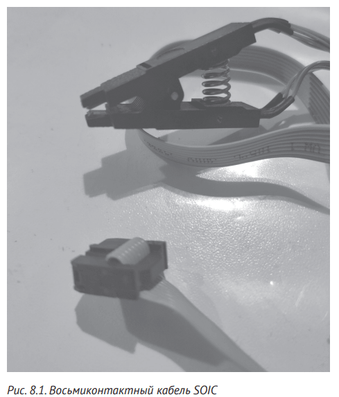
Communication with SPI and I2C will require some hardware. You can use a patch board or programmer for EEPROM/flash chips if you want to solder the chips (you should if you have no other option). But if you prefer not to unsolder the chips from the printed circuit board, you can use either special hook clamps that connect directly to the contacts of the chip, or chip clamps in the SOIC package (usually flash memory chips are found in such packages), which are cheap and convenient.
For the SPI project described in this section, you will need an eight-pin SOIC cable with a clamp or hook clamps to connect to the flash memory chips. SOIC clamps (Figure 8.1) can be tricky to use because you need to align the pads precisely when connecting the clip to the chip. Clip-hooks are more convenient to use for many.
You will also need a USB-UART adapter. Although you can use the adapter used in Chapter 7, we recommend Bus Pirate (http://dangerousprototypes.com/docs/Bus_Pirate), a robust open source device that supports multiple protocols. It has built-in macros for IoT hacking, including I2C scanning and sniffing capabilities and many other protocols. You can also try more expensive tools that parse I2C messages in more formats, such as Beagle (https://www.totalphase.com/pro ducts/beagle-i2cspi/) or Aardvark (https://www.totalphase.com /products/aardvark-i2cspi/). In this section, you’ll learn how to use Bus Pirate’s built-in macros to perform typical attacks.
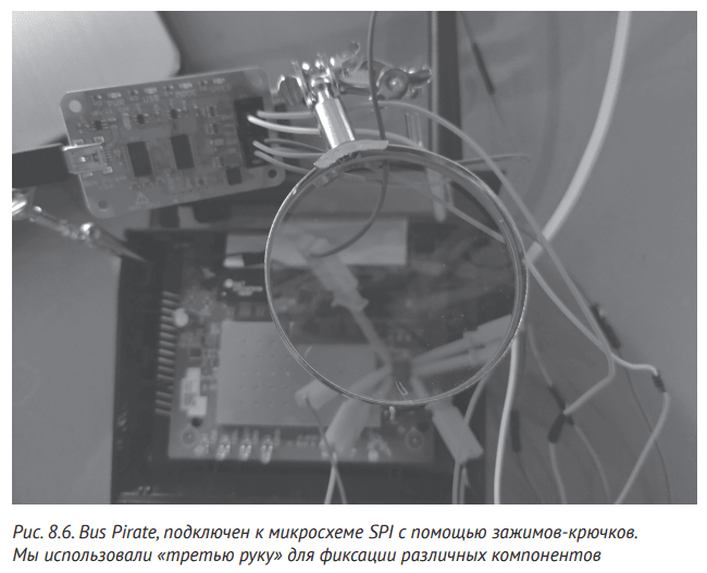
Additionally, for the I2C lab exercise (later in this section), you will need an Arduino Uno (https://store.arduino.cc/usa/ arduino-uno-rev3/), at least one BlinkM LED (https://www. sparkfun.com/products/8579/), breadboard and some patch cables. You can also use the so-called “third arm” – brackets that help hold several pieces of equipment. Their cost varies widely. The IoT Hacking Tools section provides a complete list of tools with a description of their strengths and weaknesses.
SPI is a communication protocol that transfers data between peripherals and microcontrollers. Widely used in popular hardware such as Raspberry Pi and Arduino, SPI is a synchronous communication protocol, meaning it can transfer data faster than I2C and UART. LCD displays, SD card readers and memory chips on almost any IoT device.
SPI uses four wires for data transfer. In full-duplex mode, where data is transmitted in both directions simultaneously, it relies on the architecture of the peripheral controller. In this architecture, a device that serves as a controller generates clock pulses that control data transmission, while all devices that are peripherals listen to the bus and send or receive messages. SPI uses the following four lines (not counting “ground”):
Controller In, Peripheral Out (CIPO) – for messages sent by peripheral devices to the controller;
Controller Out, Peripheral In (COPI) – for messages from the controller to peripheral devices;
Serial Clock (SCK) – clock pulses indicating when devices should be able to read data from the bus.
Chip Select (CS) is a signal to select the peripheral device that should receive the message.
Note that unlike UART, SPI uses separate lines to send and receive data (COPI and CIPO, respectively). Also note that the hardware required to implement SPI is cheaper and simpler than UART, and can provide higher data rates. For these reasons, many microcontrollers used in the IoT world support it. For more information on the SPI implementation, see the page https://learn.sparkfun.com/tutorials/serial-peripheral-interface-spi/all/.
Flash memory chips often contain device firmware and other important secrets, so extracting data from them can reveal important security information: backdoors, encryption keys, secret accounts, and more. To locate the memory chips in an IoT device, open its case and remove the circuit board.
Find the right chips and pins
Locate the device’s flash memory chip. Safety-conscious manufacturers usually remove the chip markings on the device’s board, but flash memory chips typically have 8 or 16 pins. You can also find the chip by looking up the microcontroller datasheet on the Internet, as we did in Chapter 7. The datasheet should include a diagram showing the pin configuration and descriptions. The table will likely also contain information confirming whether the microcontroller supports the SPI protocol. Other information such as protocol version, supported speeds, and memory size will also be useful when configuring tools to interface with SPI.
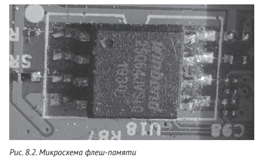
After locating the memory chip, look for the small dot in one of the corners of the chip that marks pin 1 (Figure 8.2).
Now connect the first pin of the eight-pin SOIC cable to pin #1 of the chip. The first pin of the SOIC clamp is usually colored differently, so it’s easy to find. Use the pin location information from the table to connect the rest of the SOIC pins correctly. Fig. Figure 8.3 shows a typical pin arrangement. In particular, this is how the contacts of the WinBond 25Q64 memory chip are located.
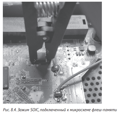
When you have connected all the parts of the SOIC clamp to the flash memory chip, your setup should look like the one shown in Fig. 8.4. Be careful when connecting the SOIC clamp: the pins are easily damaged.

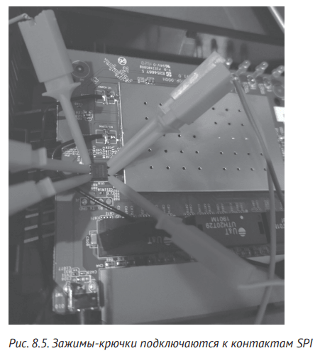
If you have problems connecting the SOIC clamp, hook clamps are also suitable (Fig. 8.5.); You may even find it easier to connect them.
You will need an adapter to read the contents of the memory chip. In this example we will use Bus Pirate, but you can use any adapter that supports the SPI protocol. If you get your hands on Bus Pirate, make sure its firmware is updated to the latest stable version.
Make sure the device you’re removing the memory from is turned off, then connect the wires to the chip. Connect the Bus Pirate pins and chips using the SOIC clamp as shown in the table. For example, we would connect the WinBond 25Q64 chip according to Table 1. 8.1.

NOTES: Your board or circuit designator may use the deprecated SPI signal names MISO and MOSI instead of CIPO and COPI respectively. You may also come across the obsolete terms master/slave instead of “controller/peripheral” in I 2C schematics and boards.
When finished, the connections should look as shown in fig. 8.6.
Now that the device whose memory you will be reading is turned off, connect the Bus Pirate USB cable to the computer. You can check the connection to the SPI chip using the Linux-flashrom utility, which can be downloaded from https://flashrom.org/Flashrom (or most package managers). The following command identifies the memory chipset:
# flashrom -p buspirate_spi:dev=/dev/ttyUSB0
Make sure you replace ttyUSB0 with the device handle assigned to the adapter. This will usually be something like ttyUSB <number> and you can type the command ls /dev/tty* to view the descriptors on your system. The utility will either detect the SPI chip or return a No EEPROM/flash device found message.
Once you’ve established a connection to the chip, you can perform a read operation to retrieve its contents. Use the flashrom command:
# flashrom -p buspirate_spi:dev=/dev/ttyUSB0 -r out.bin
The -r flag starts a read operation that saves the contents to the specified file. The -p flag specifies the name of the adapter. The Bus Pirate name in this example is buspirate_spi, but you should change it if you are using a different adapter. You should see the following result:
Found Winbond flash chip "W25Q64.V" (8192 kB, SPI).
Block protection is disabled.
Reading flash…
After executing the command, the output file must match the chip memory size specified in the command output. 8MB was specified for this chipset.
Alternatively, you can retrieve the contents of the chip using the popular spiflash.py script from the libmpsse library. Download the library at https:// github.com/devttys0/libmpsse/, then compile and install it:
# cd libmpsse
# ./configure && make
# make install
If everything works, you can run spiflash.py. To verify that the tool is correctly identifying the chip and that all pins are connected correctly, run spiflash.py and look for the chip name in the output. To retrieve the memory file stored on the chip, type the following command:
# spiflash.py -r out.bin -s <size to read>
To read, for example, an 8MB memory dump, run:
# spiflash.py -r out.bin -s $((0x800000))
If you don’t know the size of the flash dump you want to get, choose a random value large enough to hold the entire contents of the flash.
Now that you’ve removed the flash, you can run the strings utility to start viewing the information or perform further analysis with tools like binwalk. Firmware security testing will be covered in detail in Chapter 9.
I2C is a serial communication protocol for low-speed devices. Phillips Semiconductors developed I 2C in the 1980s to communicate between components on the same circuit board, but you can also use it between components connected by a cable. In the IoT world, you will often find it in microcontrollers, I/O interfaces such as keyboards and buttons, general consumer and business devices, and sensors of all types. It is important to note that even the sensors in many industrial control systems (ACS) use I2C, which is why it has become very common.
The main advantage of this protocol is its simplicity. Instead of the four wires that SPI uses, I2C has a two-wire interface. Additionally, hardware without built-in I2C support can use I2C via general-purpose I/O pins. But its simplicity, as well as the fact that all data is transmitted over the same bus, increases the risks if an attacker wants to intercept the data or inject his own. The reason is that IoT devices using the same I2C bus do not provide authentication of components.
The simplicity of I2C allows equipment to exchange data without strict speed requirements. The protocol uses three lines: a serial data link (SDA) to transfer data, a serial synchronization line (SCL) to determine the timing of data readings, and a ground line (GND). The SDA and SCL lines are connected to the peripherals and are open-drain drivers: both lines must be connected to resistors. (You’ll only need one resistor for each line, not one for each peripheral.) Voltages range from 1.8V, 3.3V to 5.0V, and transfer can occur at four different rates: 100kHz or seed rate, respectively to I2C specifications; 400 kHz – fast mode; 1 MHz for high-speed mode and 3.2 MHz for ultra-fast mode.
Like the SPI serial peripheral interface, I2C uses a controller and peripheral configuration. Components transfer data over SDA bit by bit in eight-bit sequences. A controller or controllers control the SCL line. The I2C architecture supports more than one controller and one or more peripherals, each with unique addresses used for communication. In the table Figure 8.2 shows the structure of the message sent from the controller to the peripheral device.
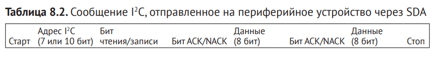
The controller starts each message with the START bus status, which signals the start of the message. It then sends the peripheral device address, which is usually 7 bits long, but can be up to 10 bits long. This allows up to 128 (when using 7-bit addresses) or up to 1024 peripherals (when using 10-bit addresses) on a single bus. The controller also adds a read/write bit that indicates the type of operation to perform. The ACK/NACK bit indicates what the next data segment will be. I2C divides the actual data into eight-bit sequences, each ending with a different ACK/NACK bit. The controller terminates the message by generating a STOP state. For more information about the protocol, visit https://www.i2c-bus.org/.
As mentioned earlier, the I2C protocol supports multiple controllers on the same bus. This is important because when connected to the bus we could act as another controller and then read and send data to the peripherals.
In the next section, we will configure our own I2C bus architecture.
To demonstrate how to monitor the I2C communication and write data to the bus peripherals, let’s build a classic communication bus architecture with the controller peripheral using the following open source hardware:
an Arduino Uno microcontroller (https://store.arduino.cc/usa/arduino-uno-rev3/), which will act as a bus controller;
one or more RGB LEDs controlled by I2C (https://www.sparkfun.com/products/8579/) – as peripheral devices. Full documentation for BlinkM LEDs, including examples of other programming methods, can be found at https://thingm.com/products/blinkm/.
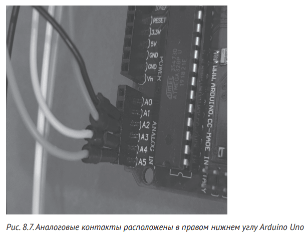
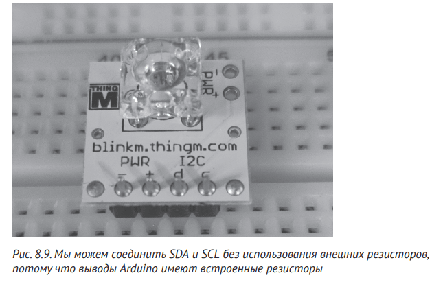
We chose to use an Arduino Uno because the analog pins that the Arduino uses for SDA and SCL have built-in resistors and we don’t have to add pull-up resistors to the circuit. In addition, it allows you to use the official Arduino Wire library to control the I 2C bus as a controller and send commands to I2C peripherals. In the table Figure 8.3 lists the analog contacts of the Arduino Uno, I2C support.

Locate pins A2, A3, A4, and A5 on the Arduino Uno, then connect the plug wires to them as shown in Fig. 8.7.
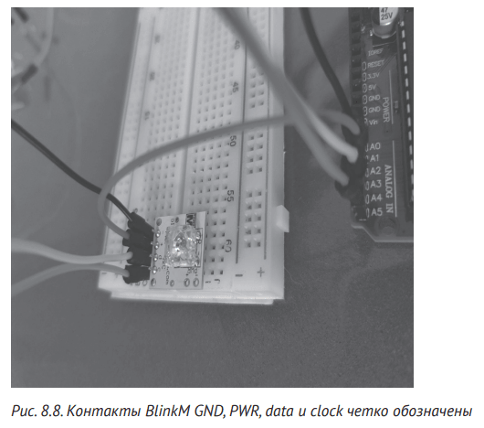
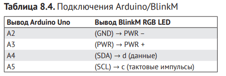
Then locate the GND (–), PWR (+), SDA (d), and SCL (c) pins on the BlinkM LED by checking the label at the top of each row of pins as shown in Fig. 8.8. Now, using the breadboard, connect the BlinkM LED and cables to the corresponding pins on the Arduino board, based on the data in Table 1. 8.4.
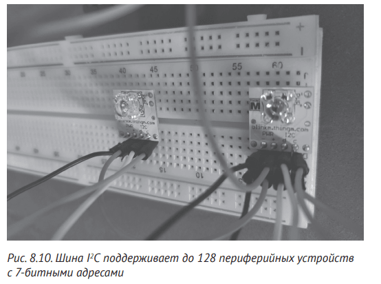
If you have more than one I2C peripheral, connect them to the same SDA and SCL lines. Select one breadboard backer for the SDA line and another for the SCL line; Then connect the devices to these lines. For example, in fig. Figure 8.10 shows two connected BlinkM LEDs. BlinkM LEDs of the same type by default have the same programmable address I 2C (0x09) as specified in the product datasheet available at https://www.infinite-electronic.kr/datasheet/ e0-COM-09000.pdf. (This goes to show why it’s always a good idea to refer to the datasheet if you have one; the information you find may save you some reverse engineering effort.
After connecting the controller (Arduino) and the peripheral (BlinkM LED), program the Arduino to connect to the I 2C bus and send some commands to the peripherals. We will use the Arduino IDE to write the program. See Chapter 7 for an introduction to Arduino and installation instructions. In the IDE, select the Arduino board you are using by clicking Tools > Board > Arduino/ Genuino UNO (Tools > Board > Arduino/Genuino Uno), then load the code in Listing 8.1.
Code listing 8.1. The I2C controller code that will control the BlinkM RGB LED
#include <Wire.h>
void setup() {
pinMode(13, OUTPUT); //Отключить встроенный светодиод Arduino
 pinMode(A3, OUTPUT); //Настроить вывод A3 как выход
 pinMode(A2, OUTPUT); //Настроить A2 как выход
 digitalWrite(A3, HIGH); //A3 в качестве источника питания
 digitalWrite(A2, LOW); //A2 в качестве GND
Wire.begin(); // Использовать шину I2C в роли контроллера
}
byte x = 0;
void loop() {
Wire.beginTransmission(0x09);
Wire.write('c');
 Wire.write(0xff);
 Wire.write(0xc4);
Wire.endTransmission();
 x++;
 delay(5000);
}
The code configures the Arduino pins for I2 C protocol communication, connects to the I2 C bus as a controller, and uses a loop to periodically send messages to peripherals with address 0x09. The message code contains commands to turn on the LEDs.
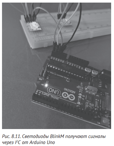
Detailed descriptions of these commands can be found in the BlinkM specification. Finally, the code sends a STOP sequence to indicate the end of the message. Now connect your Arduino Uno to your computer and upload your code. BlinkM RGB LEDs must receive commands and blink according to them (Fig. 8.11).
Let’s connect Bus Pirate to our I 2C bus and start listening to communications.
Bus Pirate firmware has built-in I 2C support. It also has some useful macros that we can use to analyze and attack I2C communications. On Bus Pirate we will use the following pins: COPI (MOSI), which correspond to the I2C SDA pin; CLK corresponding to the SCL pin; and GND. Connect these three lines from the I2C bus (Table 8.5) using jumpers.

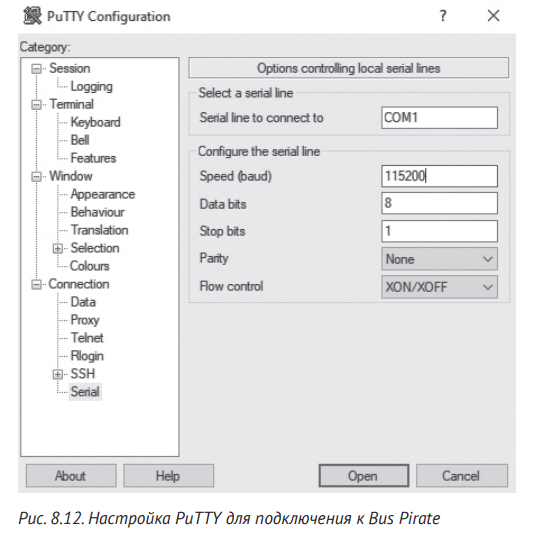
After all the contacts are connected, connect the Bus Pirate to the computer. To communicate with Bus Pirate, you need to connect to a serial communication (COM) port using the standard 115,200 baud rate. On Linux, do this using screen or minicom utilities:
$ screen /dev/ttyUSB0 115200
In Windows, open Device Manager to see the COM port number. Then use PuTTY with the configuration shown in Fig. 8.12.
After you have configured the port settings in PuTTY, click Open. You should now have a connection.
To display a list of all I2C devices connected to the bus, use the I2C Bus Pirate library to search the entire address space. This gives all connected I 2C chips as well as undocumented access addresses. Let’s start by setting up Bus Pirate mode using the m command:
I2
C >m
1. HiZ
2. 1-WIRE
3. UART
4. I2C
5. SPI
6. 2WIRE
242  Глава 8
7. 3WIRE
8. LCD
9. DIO
x. exit(without change)
Select 4 to select I2C mode, then set the desired speed:
(1)>4
Set speed:
 1. ~5KHz
 2. ~50KHz
 3. ~100KHz
 4. ~400KHz
(1)>4
Ready
We set the speed to 4, which corresponds to about 400kHz, or the I2C speed, because that’s what the Arduino Uno controller runs at. The I2C library supports two macros. The first is an address lookup macro that automatically tries each I2C address. It then looks up the response to determine how many peripherals are connected and whether you can use any other addresses, such as broadcasts. Run the macro by entering action (1):
I2
C >(1)
Searching I2C address space. Found devices at:
0x00(0x00 W) 0xFF(0x7F R)
This macro displays the addresses followed by the 7-bit address with a bit indicating whether the address is read or written. In this case, we see addresses 0x00 (W), the broadcast address of BlinkM, and address 0x7F, which belongs to the BlinkM LED.
The second macro built into the Bus Pirate I 2C library is a sniffer. It displays all START/STOP sequences, ACK/NACK bits, and data transmitted via SPI and I 2C 205 over the I2C bus. Again we need to put Bus Pirate into I 2C mode, select the speed and then execute macro number two with command (2):
I2
C >(2)
Sniffer
Any key to exit
[0x12][0x12+0x63+]][0x12+0x63+0xFF+0xC4+][0x12+0x63+]][0x12+0x63+]]
[0x12+0x63+]][0x12+0x63+]][0x12+0x63+0xFF+0xC4+][0x12+0x63+0xFF+0xC4+]
[0x12+0xC6-0xFD-][0x12+0x63+0xFF+]
The captured data is displayed on the screen in Bus Pirate message format for I 2C, which allows us to copy and paste the message to play it at will. Table 8.6 shows the syntax used by Bus Pirate to represent I2C symbols.
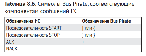
Verify that your sniffer is working correctly by comparing the sniffer data with the data sent by the Arduino Uno. Now, to send data to any of the peripherals on the bus, type a message directly into the Bus Pirate prompt, or copy any message you want to play. We can see the structure of the commands for changing the colors in the I2 C traffic and, looking at the technical description of the LED, draw conclusions about this structure. Now let’s check it by repeating the command:
I2C>[0x12+0x63+0xFF+0xC4+]
I2C START BIT
WRITE: 0x12 NACK
WRITE: 0x63 NACK
WRITE: 0xFF NACK
WRITE: 0xC4 NACK
I2C STOP BIT
The output shows the sequence bits and the data you sent on the bus. Analyze bus traffic on your devices to spot patterns, then try sending your own commands. If you have used the I2C demo bus shown in this section, you may find more suitable commands in the BlinkM datasheet.
The replay frequency of this command is quite low; We just make the LED flash in the right order. But in real attacks, you can use the same technique to record MAC addresses, flags, or factory settings, including serial numbers. Using the same approach we used here, you should be able to find the I2C buses on any IoT device and then analyze the communication between the components to read and send your own data. Also, due to the simplicity of this protocol, it is likely that you will encounter it on all types of devices.
In this chapter, you learned about the two most common protocols found in hardware IoT devices: SPI and I 2C. Fast peripherals are more likely to implement SPI, while I2C can be implemented in software even in microcontrollers that do not have a hardware I2C module due to its simplicity and low hardware requirements. The techniques and tools we discuss allow you to disassemble devices and analyze them to understand their functions in order to identify security weaknesses. Throughout this chapter, we’ve used Bus Pirate, one of the many great tools available for interfacing with SPI and I2C. This open source board has robust support for most IoT communication protocols, including built-in macros to analyze and attack a wide range of IoT devices.
We used materials from the book “The Definitive Guide to Attacking the Internet of Things” written by Photios Chantsis, Ioannis Stais, Paulino Calderon, Evangelos Deirmentsoglu and Beau Woods.