
How to get started with STM32: a complete guide for those already familiar with Arduino

Timers are one of the most important hardware modules of STM32 microcontrollers. This article discusses the fundamental principles of STM32 timers, their configuration and practical usage scenarios. The material will be useful for both beginners and experienced embedded system developers. You will learn how to configure timers in STM32CubeIDE using HAL (Hardware Abstraction Layer), create timer interrupts, implement precise delays without using HAL_Delay() and generate PWM signals to control LEDs, motors or other devices.
Timers are, without exaggeration, one of the key components of microcontrollers (after the core itself, of course). They are based on a regular counter that counts down to a given value, then resets (for example, to zero) and starts counting again. It seems like nothing complicated — after all, we could implement the same logic in a regular for loop, simply incrementing a variable.
Yes, it is possible, but in this case the core of the microcontroller will not be able to do any other (higher priority) tasks, because it will be busy with this primitive counting. That is why using timers allows you to unload the core and transfer more important work to it.
To better understand the value of timers, let’s look at a simple example.
int main()
{
  HAL_Init();
  GPIO_PA4_Init();  //Init LED1

  while (1)
  {
    toggleLed1();
    HAL_Delay(1000);
  }
}
The program above is a simple “blinker” that turns an LED on or off once every second. At first glance, there’s nothing wrong with this code, and it really is. The problems arise when you need to perform other periodic tasks at intervals other than one second.
For example, you might want to read data from a temperature sensor every half second, and turn a second LED on another output every one and a half seconds. Of course, you could also implement the program in such a way that all of this works:
int main()
{
  HAL_Init();
  GPIO_PA4_Init();  //Init LED1
  GPIO_PA11_Init(); //Init LED2

  while (1)
  {
    readTemp();
    HAL_Delay(500);

    readTemp();
    HAL_Delay(500);

    toggleLed1();
    HAL_Delay(500);

    toggleLed2();
  }
}
The updated example also works, but now has more complex logic. From the code above, it is not immediately clear why the readTemp() function is called exactly 3 times in the while loop or why the toggleLed1() function is called exactly after the 2nd call to readTemp().
In addition, the example above was ideally chosen so that the intervals of all 3 operations were multiples of 500 milliseconds and therefore are relatively easy to “use” in one while loop. But imagine a less ideal example: the temperature reading operation should be performed once every 400 milliseconds, not 500. In this case, the code would look like this:
int main()
{
  HAL_Init();
  GPIO_PA4_Init();  //Init LED1
  GPIO_PA11_Init(); //Init LED2

  while (1)
  {
    readTemp();
    HAL_Delay(400);
    readTemp();
    HAL_Delay(400);
    readTemp();

    HAL_Delay(200);
    toggleLed1();

    HAL_Delay(200);
    readTemp();

    HAL_Delay(300);
    toggleLed2();

    HAL_Delay(100);
  }
}
To read the temperature every 400 milliseconds, we had to manually go through the code in a while loop and set different delay values not only before calling readTemp(), but also before all other functions. And if, say, we need to change the interval to 300 ms, we will have to recalculate everything again and set new delay values in the appropriate places.
And what if we need to switch the Led1 LED not once a second, but every 700 ms? And what if these intervals also need to be changed dynamically — right while the device is running? For example, when a button is pressed, the blinking of Led1 should accelerate by 100 ms compared to the mode when the button is not pressed. I hope the logic is clear. It is possible to implement all this programmatically, but you will have to make a lot of effort, constantly coordinating the delays between three separate functions.
It would be much more convenient if there was a simple tool that allows you to simply set the execution interval of a certain function — without taking into account other parts of the code. This is exactly the role that timers play.
P.S.: an alternative approach to solving this problem could be an RTOS with built-in mechanisms for periodic tasks, but that’s a completely different story.
Timers are separate hardware blocks in the microcontroller that operate separately from the core and often even at a different frequency. In addition to the simple function of a counter, they can also:
generate interrupts.
generate signals on pins (GPIO.
control motors (stepper, brushed, brushless).
automatically restart the microcontroller in case of a malfunction (watchdog timer).
analyze input signals (their pulse duration, periods.
and many others that you can imagine.
* Watchdog timers, although they are called timers, still have a different purpose from those considered in this article. Therefore, we will not consider them here
That is, the functionality of timers is actually much broader than just the counter function. Let’s look at a few examples of simple applications of timers and start with the counter function.
Let’s start with the simplest example, which demonstrates how to start a timer in regular counter mode. But first, you need to familiarize yourself with the parameters with which you can start a timer:
timer frequency (set by a divider – prescaler)
number to count to – period
counter mode (count up or down, i.e. from 0 to 1000 or from 1000 to 0)
The frequency of the timer determines how many times per second its counter can increment. For example, if it is 8 MHz, this means that in one second the timer can potentially count up to 8 million steps. The source of this frequency is usually the APB (Advanced Peripheral Bus) bus, which in most cases is synchronized with the clock frequency of the microcontroller core. That is, if the MK runs at 16 MHz and no divider is used, then the timer also runs at a frequency of 16 MHz, and theoretically the counter can reach 16 million in one second.
However, in practice we will not achieve such a value, and here is why. Timers have a “period” parameter that determines the value to which the counter must count before resetting to zero. It is this period that limits the maximum possible number that we can set. For example, for a 16-bit timer, this limit is 65,535, and for a 32-bit one — over 4 billion. And this is absolutely normal, because in most cases such high accuracy is not needed.
So, the timer resolution is simply a technical limitation that determines its maximum counting range. When the timer reaches the value set in the “period” field, it overflows and starts counting again.
Using the example of STM32G030F6P6 (8KB/32KB/TSSOP-20), let’s look at the initialization and start of the timer:
void example1()
{
    HAL_TIM_Base_Stop(&htim3);
    HAL_TIM_Base_DeInit(&htim3);
    __HAL_RCC_TIM3_CLK_ENABLE();

    htim3.Instance = TIM3;
    htim3.Init.Prescaler = 16000 - 1;   //downclock timer to 1000Hz
    htim3.Init.Period = 6000 - 1;       //count to 6000 (6 sec)
    htim3.Init.CounterMode = TIM_COUNTERMODE_UP;
    HAL_TIM_Base_Init(&htim3);
    HAL_TIM_Base_Start(&htim3);
}
In the case of STM32G030F6P6, the default core frequency is 16 MHz (although it can also run at 64 MHz). By setting the divider to 16,000, we forced the timer to run at a frequency of 1000 Hz (16MHz / 16k), i.e. to make 1000 increments per second. And by setting the period to 6,000, we forced it to count up to 6 seconds (6000/1000).
Let’s run this example and look at the timer counter value in debug mode:
The video shows how the counter counts up to 6000 and starts over each time. But there is not much use in such an example – the counter simply counts as we set it and that’s it. It would be nice if we could still perform the action we need every time the timer counts up to the given number. This can be achieved by running the timer in interrupt mode, as in the following example.
This example is similar to the previous one, with the only difference being that when the counter reaches the given period, the timer will generate an interrupt, in which we will place the code we need – for example, blinking an LED.
void example2()
{
    HAL_TIM_Base_Stop(&htim3);
    HAL_TIM_Base_DeInit(&htim3);
    __HAL_RCC_TIM3_CLK_ENABLE();

    htim3.Instance = TIM3;
    htim3.Init.Prescaler = 16000 - 1;
    htim3.Init.Period = 2000 - 1;

    HAL_TIM_Base_Init(&htim3);
    HAL_NVIC_SetPriority(TIM3_IRQn, 0, 0);
    HAL_NVIC_EnableIRQ(TIM3_IRQn);
    HAL_TIM_Base_Start_IT(&htim3);
}

void HAL_TIM_PeriodElapsedCallback(TIM_HandleTypeDef *htim)
{
  if (htim->Instance == TIM3)
  {
    HAL_GPIO_TogglePin(GPIOA, GPIO_PIN_4);
  }
}
In the example, we used the same divider, but now we count to 2000, that is, to 2 seconds. We also enabled interrupts for our timer (TIM3) with the highest priority, that is, 0. And what is no less important — we started the timer in interrupt mode via HAL_TIM_Base_Start_IT. And below we described the code that will be called for each interrupt: blinking the LED on pin PA4.
This example is already more useful than just a counter. But it can be improved if the blinking of the LED itself is put on the shoulders of a timer. To do this, consider the following example.
In the previous example, we have already freed up the resources of the MK core by delegating the countdown to the timer. And only when the timer generates an interrupt, the core has to interrupt its work to switch the LED. But it is even better – you can delegate the work with the LED to the timer. Since the timer is a hardware module, it can have a physical connection to the GPIO, that is, it can also control the LED.
To do this, we will use the timer mode, which is called the Output Compare mode. This mode has many submodes of operation, which, although they do not differ much from each other, each has its own application. For example, one of such submodes is TIM_OCMODE_TOGGLE – switching. That is, we are going to use the timer in the comparison mode with the switching submode. Just do not get confused.
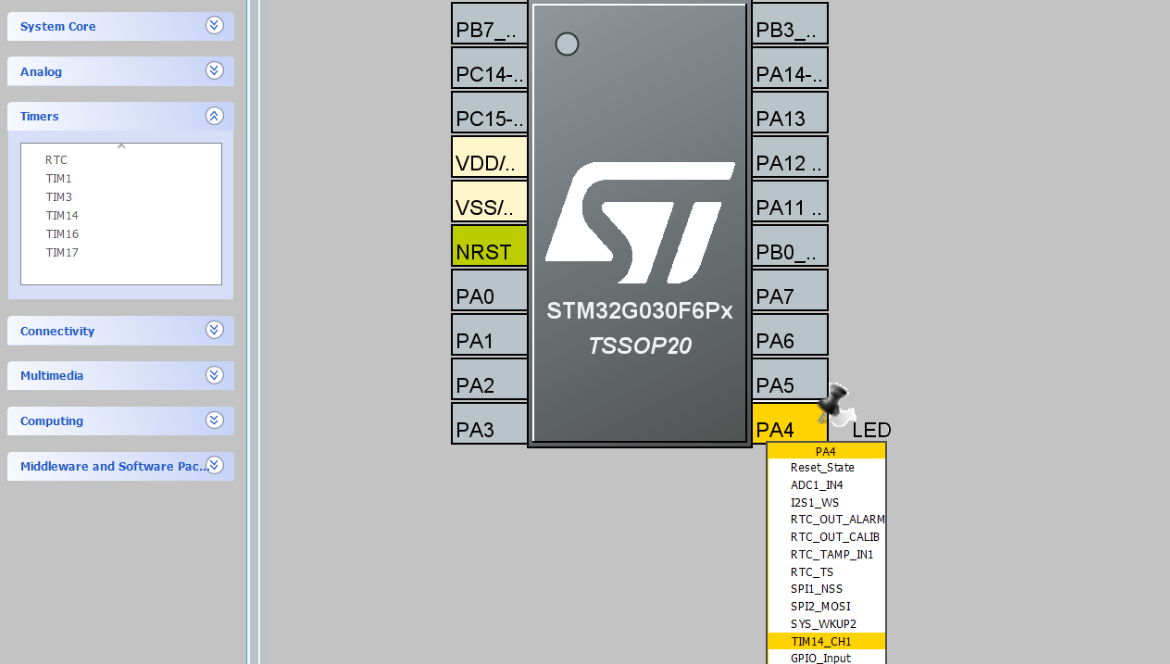
But here too, everything is not so simple. Any timer cannot be connected to any GPIO to control it. Only certain channels of certain timers can be connected to certain pins. To find out which timer can be connected to which pin, you need to refer to the STM32G030F6P6 datasheet (page 35) or to the STM32CubeIDE, which will tell us that the LED on pin PA4 can be connected to channel 1 (CH1) of timer 14 (TIM14).
An example looks like this:
void example3()
{
   HAL_TIM_Base_Stop(&htim14);
   HAL_TIM_Base_DeInit(&htim14);
   __HAL_RCC_TIM14_CLK_ENABLE();

   htim14.Instance = TIM14;
   htim14.Init.Prescaler = 16000 - 1;       //downclock timer to 1000Hz
   htim14.Init.Period = 5000 - 1;           //count to 5 seconds
   HAL_TIM_OC_Init(&htim14);

   TIM_OC_InitTypeDef htimOcConfig = {0};
   htimOcConfig.OCMode = TIM_OCMODE_TOGGLE; //GPIO Toggle mode
   htimOcConfig.Pulse = 2500;               //do toggle in 2.5s - middle between 5s
   HAL_TIM_OC_ConfigChannel(&htim14, &htimOcConfig, TIM_CHANNEL_1);
   HAL_TIM_OC_Start(&htim14, TIM_CHANNEL_1);
}

void GPIO_PA4_TIM_OC_Init()
{
 __HAL_RCC_GPIOA_CLK_ENABLE();
 GPIO_InitTypeDef GPIO_InitStruct = {0};
 GPIO_InitStruct.Pin = GPIO_PIN_4;
 GPIO_InitStruct.Mode = GPIO_MODE_AF_PP;     //Init GPIO PA4 as Alternate Function
 GPIO_InitStruct.Alternate = GPIO_AF4_TIM14; //Init GPIO PA4 as Alternate Function 4
 HAL_GPIO_Init(GPIOA, &GPIO_InitStruct);
}
You also need to initialize the PA4 pin in the AF4 alternative function mode according to the datasheet (or STM32CubeIDE). Let’s run the example:
As you can see from the example, the LED is not switched every 5 seconds as you might think from the period parameter, but in the middle – every 2.5 seconds. This is all because of the new pulse parameter that we set.
The last example is very similar to the previous one and is also considered a comparison mode. Here we change the brightness of the LED by setting the required duty cycle to the variable pulse. We start with 50% (500/1000) and then increase it by 5% every 100 milliseconds.
Importantly, the frequency of the timer in PWM mode must be significantly higher than in the previous examples so that the blinking of the LED becomes imperceptible to a person. Therefore, we set the frequency to 1 MHz using the divider. The PWM period can be adjusted by the timer frequency (i.e. the divider) and the period.
void example4()
{
    HAL_TIM_Base_Stop(&htim14);
    HAL_TIM_Base_DeInit(&htim14);
    __HAL_RCC_TIM14_CLK_ENABLE();

    htim14.Instance = TIM14;
    htim14.Init.Prescaler = 16 - 1; //downclock timer to 1 MHz
    htim14.Init.Period = 1000 - 1;   //count to 1000

    TIM_OC_InitTypeDef htimOcConfig = {0};
    htimOcConfig.OCMode = TIM_OCMODE_PWM1;
    htimOcConfig.Pulse = 500;        //startup duty cycle - 50% (500/1000)

    HAL_TIM_PWM_ConfigChannel(&htim14, &htimOcConfig, TIM_CHANNEL_1);
    HAL_TIM_PWM_Init(&htim14);
    HAL_TIM_PWM_Start(&htim14, TIM_CHANNEL_1);

    while (1)
    {
        htimOcConfig.Pulse = htimOcConfig.Pulse + 50;
        if (htimOcConfig.Pulse >= 1000)
        {
            htimOcConfig.Pulse = 0;
        }
        HAL_TIM_PWM_ConfigChannel(&htim14, &htimOcConfig, TIM_CHANNEL_1);
        HAL_Delay(100);
    }
}

void GPIO_PA4_TIM_OC_Init()
{
  __HAL_RCC_GPIOA_CLK_ENABLE();
  GPIO_InitTypeDef GPIO_InitStruct = {0};
  GPIO_InitStruct.Pin = GPIO_PIN_4;
  GPIO_InitStruct.Mode = GPIO_MODE_AF_PP;
  GPIO_InitStruct.Alternate = GPIO_AF4_TIM14;
  HAL_GPIO_Init(GPIOA, &GPIO_InitStruct);
}
After setting up the timer and pin in the while loop, we change the pulse from 0 to 1000, thereby adjusting the duty cycle from 0% to 100%.
This is how we smoothly change the brightness of the LED using a timer and PWM.
At first glance, timers in microcontrollers may seem like something simple and not very useful — ordinary counters. However, in practice, they are able to perform tasks no less efficiently than the core itself. In addition to the described use cases, there are many more modes of operation of timers and ways of their application. At the initial stage of project development, you can do without them, but over time, as the functionality of devices becomes more complicated, their mastery becomes necessary.
Link to the original source: https://solderkid-blog.netlify.app/stm32/neopixel


