28.05.2025
13 min
1057

The STM32 and TM1650 are a solid combination for driving 7-segment LED displays in microcontroller projects. In this part of the series, we will show you how to connect the TM1650 to the STM32, configure data exchange via an I2C-like interface, and display the desired information on the display.
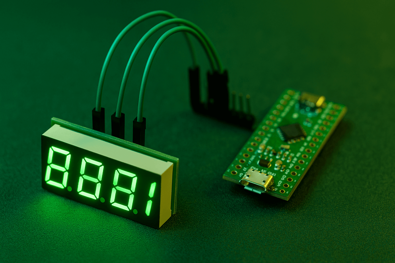
At some point, the idea arose to launch a 7-segment LED display using the ultra-cheap TM1650 chip. As of the end of 2024, when the dollar exchange rate was approximately 42 hryvnias per unit, the average cost of the TM1650 in domestic stores was about 6 hryvnias, and on international platforms – 1.5–2 times cheaper.
Given the functionality, this price is almost symbolic. The TM1650 supports multiplexing, which allows you to increase the number of used inputs or outputs in the circuit. This allows, for example, to control a standard 7-segment display (actually 4 characters of 8 segments are supported), or to read data simultaneously from 28 buttons.
The chip is controlled either via the I2C interface, or by directly generating signals from the GPIO pins – by simulating the data bus and clock bus.
The simplest option was chosen for the implementation of the project – the use of the I2C interface. However, it later turned out that full-fledged I2C support is not actually provided in the TM1650. At least, there is no direct mention of this interface in the datasheet.
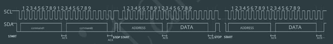
However, the analysis of the communication protocol, given in the technical documentation, demonstrates the characteristic features inherent in I2C. The structure of the transmitted data clearly shows such elements as addressing, confirmation bits (ACK), as well as signals for the start and end of transmission – START and STOP.
Although the manufacturer of the chip — the Chinese company Titan Microelectronics — does not explicitly declare support for the I2C interface, in practice the TM1650 can still be controlled using the I2C peripherals of the microcontroller. At the same time, there is an important nuance: the chip does not have a single fixed address, as is typical for classic I2C devices.
Instead, each individual operation has its own address. That is, the number of permissible operations directly determines the number of addresses. This means that for stable operation with the TM1650 it is recommended to use a separate I2C bus or fully emulate data exchange via free GPIO pins of the microcontroller.
Below is a list of addresses that correspond to specific operations performed with the LED display:
0x68 – set the value in the 1st character of the display.
0x6A – set the value in the 2nd character of the display.
0x6C – set the value in the 3rd character of the display.
0x6E – set the value in the 4th character of the display.
0x48 – display control: turn on/off the display, change the brightness, turn on/off support for the 8th segment – decimal point.
Setting a symbol on the display is very simple: you need to send a value to the desired address. The value is formed based on which segments you want to turn on.
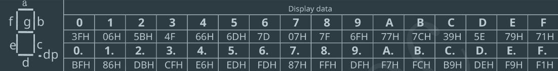
In order for the number 7 to appear in the first position of the 7-segment display, it is necessary to send the byte 0b00000111 (i.e. 0x07) to address 0x68. This value activates segments a, b and c, which are responsible for the shape of the number 7. The three least significant bits (LSB) must be active, which forms the corresponding pattern.
Another example is displaying the number 0. To do this, it is necessary to activate segments a, b, c, d, e and f, which forms the binary pattern 0b00111111, or in hexadecimal representation – 0x3F.
If you need to display a zero with a decimal point, then the 8th bit (DP – decimal point) is also activated. As a result, the pattern 0b10111111 is formed, which corresponds to the value 0xBF.
The given table with values for symbols is not complete – if necessary, you can create your own templates for new symbols or use examples from the network. For example, it is possible to display the symbols r, a, S, L, H, h, etc. – taking into account the limitations of the 7-segment matrix.
The display is controlled at address 0x48. The principle is the same as with character output: you need to send 1 byte of data to this address. You can find out which bits are responsible for what from this table:
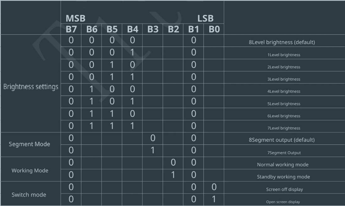
To set the 4th brightness level when the display is active, you need to send the byte 0b01000001 (i.e. 0x41) to address 0x48. This value activates the display and at the same time sets the desired brightness level.
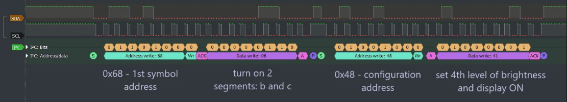
To better understand the process, it is useful to analyze the real data exchange using a logic analyzer. The example will consider how the byte transfer looks when displaying the number 1 (formed by segments b and c, i.e. 0b00000110 or 0x06) to the first position of the display (address 0x68), and also how the brightness setting (0x41) looks like when transmitting to address 0x48. Signal analysis allows you to see in detail the sequence of START, address, data, ACK and STOP, which form a full transaction in the conditionally I2C compatible TM1650 protocol.
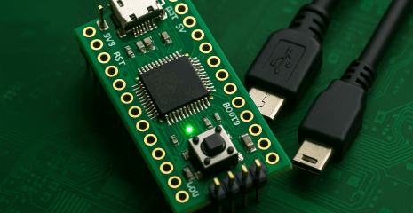
As a microcontroller, one of the most economical options was used – STM32G030 (64 MHz clock speed, 8 KB RAM, 32 KB flash memory) from WeAct Studio, purchased via AliExpress. When ordering from five pieces, the cost is approximately 55 hryvnias per module, and the cost of the microcontroller itself (without a board) is about 17 hryvnias, which makes it one of the most affordable in its class.
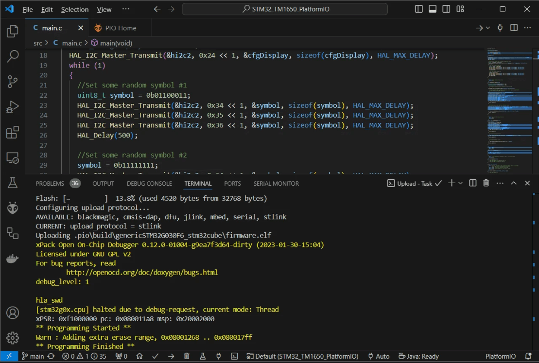
The code was generated in STM32CubeIDE, and the assembly was performed in Visual Studio Code using the PlatformIO extension, which automatically pulls up the necessary HAL dependencies for STM32G030. In addition, PlatformIO supports loading the assembled firmware onto the microcontroller via various interfaces – the interface type is specified in the platformio.ini configuration file.
While working with this series, a problem arose due to the fact that STM32G0 is a relatively new line, and PlatformIO still uses an outdated version of the stm32flash utility, which does not support this series of microcontrollers. The README.md file for the project indicates where to find the current version of the stm32flash utility and how to correctly install it manually. This problem probably does not manifest itself on Linux-based systems.
int main(void)
{
  HAL_Init();           //Reset of all peripherals, Initializes the Flash interface and the Systick.
  SystemClock_Config(); //Configure the system clock
  MX_GPIO_Init();       //Initialize all configured peripherals
  MX_I2C2_Init();

  //Turn display on and set 4 (middle) brightness level
  uint8_t cfgDisplay = 0b00100001;
  HAL_I2C_Master_Transmit(&hi2c2, 0x24 << 1, &cfgDisplay, sizeof(cfgDisplay), HAL_MAX_DELAY);
  while (1)
  {
    //Set some random symbol #1
    uint8_t symbol = 0b01100011;
    HAL_I2C_Master_Transmit(&hi2c2, 0x34 << 1, &symbol, sizeof(symbol), HAL_MAX_DELAY);
    HAL_I2C_Master_Transmit(&hi2c2, 0x35 << 1, &symbol, sizeof(symbol), HAL_MAX_DELAY);
    HAL_I2C_Master_Transmit(&hi2c2, 0x36 << 1, &symbol, sizeof(symbol), HAL_MAX_DELAY);
    HAL_Delay(500);

    //Set some random symbol #2
    symbol = 0b11111111;
    HAL_I2C_Master_Transmit(&hi2c2, 0x34 << 1, &symbol, sizeof(symbol), HAL_MAX_DELAY);
    HAL_I2C_Master_Transmit(&hi2c2, 0x35 << 1, &symbol, sizeof(symbol), HAL_MAX_DELAY);
    HAL_I2C_Master_Transmit(&hi2c2, 0x36 << 1, &symbol, sizeof(symbol), HAL_MAX_DELAY);
    HAL_Delay(500);
  }
}
According to the code example, the first step is to send a configuration byte to address 0x48 (corresponding to offset 0x24 << 1), which activates the display and sets the 4th brightness level. After that, in the while loop, different characters are displayed on the display in turn.
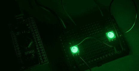
One of the characters activates all 8 available segments at the same time, demonstrating that the bit is completely full. In the demonstrated example, only 3 display positions are involved, since a three-digit 8-segment LED display was used in the test configuration. The unpleasant flickering recorded on the video is only visible through the camera – in real conditions, the indication looks stable and clear to the human eye.
In most cases, installing a capacitor on the TM1650 power pin is critical, as without it the chip is prone to unstable operation or freeze completely. For conditions of average brightness level, a capacitance of 100 μF is usually sufficient.
This is explained by the fact that the TM1650 works on the principle of multiplexing: the driver switches the active segments extremely quickly, and in fact only one character is lit at any given time. However, due to the high cycle frequency, it seems to the human eye that all characters are lit simultaneously.
Such fast and constant switching of the load (LED) creates significant pulse voltage drops, especially with low-impedance power supplies. As a result, the decoupling capacitor ceases to be just a recommended element – it becomes a necessary condition for the stable operation of the entire system.
The project is hosted on GitHub. VS Code + PlatformIO was used for development:
TM1650 is an extremely affordable LED display driver that is ideal for use in the budget segment of devices, where the key requirements are minimal cost and ease of implementation.
Despite its low price, the chip has certain features that should be taken into account when developing. Among them are the non-standard implementation of the I2C-like interface and the lack of universal addressing, due to which each operation has a separate address. This creates some inconveniences when integrating into more complex systems or when sharing the same I2C bus with other devices.
However, in the context of the functionality/cost ratio, the TM1650 looks very attractive. For comparison, the HT16K33 — one of the popular alternative drivers — costs 5 times more, and some other analogues — tens of times more expensive.
Taking all factors into account, the TM1650 can be an excellent choice for budget projects, especially when simple indication is required and complex bus interaction logic is not planned. Provided proper connection, stable power supply, and protocol specifics are handled, the chip demonstrates stable operation and good compatibility with the STM32 family.
Link to the original source: https://solderkid-blog.netlify.app/stm32/neopixel