28.05.2025
13 min
1057

Continuing the topic of timers, we should look at another of their operating modes that was skipped in the previous article — Input Capture mode. We’ll explore it using the example of a wireless data transmission protocol developed by the Japanese company NEC. Today, NEC belongs to Renesas, which is in turn owned by the Japanese conglomerate Hitachi (which, by the way, also owns GlobalLogic). The NEC protocol is one of the most popular protocols for data transmission via infrared (IR) signals, especially in Japanese consumer electronics. It is still used today for controlling low-cost household appliances.

Infrared data transmission can be considered a predecessor of modern Bluetooth and Wi-Fi, though both of the latter are significantly more advanced. IR data transmission was widely used in the past: mobile phones, pagers, regular remotes, and even printers, video cameras, and the Nintendo Game Boy.
Let’s begin by understanding the physical layer of IR signal transmission:
- The transmitter (remote) emits pulses of invisible infrared light (wavelength ~940 nm) at a frequency of 38 kHz.
- The receiver detects these high-speed light pulses and outputs a constant low voltage level on its Data pin for as long as it detects incoming pulses. When the pulses stop, the output goes high again. This creates the following waveform:
Electrical Signal
Once the IR receiver converts light pulses into an electrical signal, the structure of this signal is as follows:
- Each message begins with a long pulse (low level) of 9 ms followed by a pause (high level) of 4.5 ms.
- Data bits are not encoded by the pulse itself but rather by the duration of the pause after each pulse.
- Pulse duration is fixed at 562.5 μs. If this is followed by a pause of the same length, it means bit 0; if followed by a pause of 3 × 562.5 μs, it means bit 1.
- Precise timing of 562.5 μs may not always be achieved due to hardware tolerances, so a few percent of deviation should be accounted for in the code.
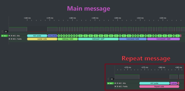
- The data structure consists of: 8 bits of address, followed by 8 bits of inverted address, 8 bits of command, and 8 bits of inverted command.
- The inverted address and command serve as a simple checksum to validate that the original 8 bits were received correctly.
- The end of the message (after 32 bits of data) is marked by a final pulse of 562.5 μs.
- If the user holds the button after the main message, a short repeat packet is sent every 108 ms: a 9 ms pulse + 2.25 ms pause + 562.5 μs pulse.
All of this can be seen clearly using a logic analyzer diagram.
Now that we have a good idea of what the signal looks like, let’s see how it can be captured using a timer. A timer doesn’t magically capture the whole signal at once — although that would be convenient. What it actually does is record its counter value in a special register at each edge of the signal.
So, to capture the whole signal, we need to store the timer’s counter values at every signal edge, then calculate the time difference between consecutive values to determine the duration of each pulse. We need to do this for all edges throughout the message.
In practice, it’s sufficient to capture timer values on falling edges only and calculate the difference between them to determine the pulse timing, as seen in the waveform diagram.
Timers are hardware blocks inside the MCU, but they don’t have dedicated pins. Instead, they must be connected to existing GPIOs set to alternate function mode. Not every timer can be connected to every GPIO — valid combinations are listed in the MCU’s datasheet.
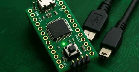
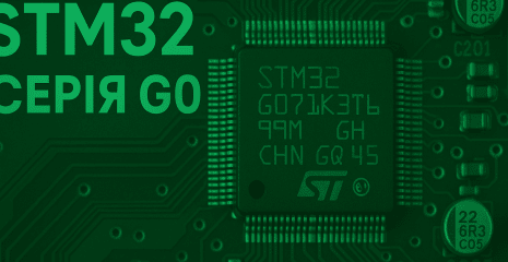
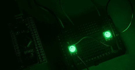
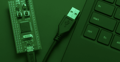
On my STM32G030F6P6, I chose pin PA11, which can be connected to channel 4 of TIM1, according to the datasheet. I connected this pin to an IR module from AliExpress (cost: $0.60). The module has just three pins: VDD, GND, and Data. The Data output is where our signal appears, so we connect it to PA11.
We’ll now decode the signal. First, we initialize the timer and GPIO:
uint16_t prevValue = 0;
uint32_t fullMessage = 0;
uint8_t bitIndex = 0;
void processSignal(TIM_HandleTypeDef *htim) {
uint16_t curValue = HAL_TIM_ReadCapturedValue(htim, TIM_CHANNEL_4);
uint16_t pulseWidth = (curValue>prevValue) ? curValue-prevValue : (0xFFFF-prevValue)+curValue;
prevValue = curValue;
if (pulseWidth > 12825 && pulseWidth < 14175) // (9ms + 4.5ms) ± 5% — start message
{
bitIndex = 0;
fullMessage = 0;
}
else if (pulseWidth > 1068 && pulseWidth < 1181) // (562.5μs + 562.5 μs) ± 5% — received '0'
{
bitIndex++;
}
else if (pulseWidth > 2137 && pulseWidth < 2362) // (562.5μs + 3*562.5 μs) ± 5% — received '1'
{
fullMessage |= 1 << bitIndex;
bitIndex++;
}
if (bitIndex >= 32) { // Finish!
uint8_t address = fullMessage & 0xFF;
uint8_t command = (fullMessage >> 16) & 0xFF;
// Successfully decoded!!! Now do reaction here.
}
}
That’s how easily, in just a few if-statements, we decoded an IR signal using a timer:
- The
processSignalfunction is called each time the signal level falls.- In the first
if, we check whether this is a long 9-millisecond pulse followed by a 4.5 ms pause. If so — we clear the previous data packet and begin reading the data bits in the next function call.- In the second
if, we check whether it’s a 562.5 μs pulse followed by a short 562.5 μs pause. If so — we register a 0.- In the third
if, we check whether it’s a 562.5 μs pulse followed by a long 3 × 562.5 μs pause. If so — we register a 1 and shift it into a 32-bit variable.- In the final
if, we check if we have read all 32 bits. If so — we consider the data packet received.The full demo was written for the STM32G030F6P6 (32KB/8KB/TSSOP-20) with the standard core frequency of 16 MHz and published on GitHub.
The code above is very simple but fully functional (see the demo video). However, several improvements could be made:
- Validate the “checksum” present in the signal (the inverted command and address) to confirm the correctness of received data.
- Handle repeat messages so that holding a button on the remote continues triggering actions.
- In the current code, the end of transmission is assumed after receiving the 32nd data bit. However, a more accurate approach would process the final trailing pulse.
- For complexity, DMA could be used to automate reading signal timing (a topic for another time).
- For simplification, any timer could be used without binding it to GPIO. Instead, an interrupt can be attached to the GPIO directly. Since the IR signal is relatively slow, precise timer resolution is not critical in this case.
Conclusion
In this and the previous article, we explored some simple examples using timers to understand what they are and how they can be used. But the topic of timers is vast and far from exhausted.
Link to the original source: https://solderkid-blog.netlify.app/stm32/neopixel