
05.05.2023
6 min
4810

You will learn how the USB-C standard and Power Delivery technology work, which allows voltage matching between devices. The article explains how you can adapt an old power supply to the modern standard using specialized components such as PD controllers and MOSFETs.

What to do if you need to create your own USB-C power supply? The good news is that it’s really easy! For example, if you have a Lenovo, HP, or Dell power supply with a voltage of 19-20 V, you can convert it to USB-C without much effort. Upgrading such a device requires only a few simple steps and small modules that will ensure compliance with the USB-C standard. This approach allows you to achieve the desired result without unnecessary complications or significant deviations from the specification.
Converting a 20V power supply into a USB-C power supply is a logical solution, especially if you need to charge your laptop. Most laptops work with 20V via USB-C, but there is one important detail here. Simply connecting 20V to the USB-C connector will not work – you need to add some logic to make such a power supply safe for devices that require 5V. In addition, before applying 20V to VBUS, you need to perform several additional steps.
According to the USB-C standard, any power supply must first output 5V as soon as the device is connected. Only after the power supply is digitally matched with the connected device is it allowed to switch to a higher voltage, if necessary.
To do this, the power supply offers a set of profiles. Each profile describes the voltage, the maximum current for this voltage, and several additional parameters. According to the USB-C specification, in addition to the basic 5 V, 9 V, 15 V, and 20 V can also be provided, making the power supply universal for different types of devices.
According to the USB-C specification, if a power supply supports a certain voltage, for example 15 V, it must also support all voltages that are lower than this limit, defined by the standard. For example, for 15 V, 9 V must also be supported. This is more of a UX requirement than a technical one: this approach simplifies the interaction between devices and power supplies, because a smaller set of voltages makes it easier to work with different chargers. However, technically the power supply can offer any voltage. In the worst case, the device will refuse to accept it and will charge more slowly than the basic 5 V, which must be implemented.
Next, we will consider how standard USB-C power supplies work, what parameters can be used to create them. Ultimately, this opens up the opportunity to build your own USB-C power supply from scratch, taking into account all the requirements and recommendations of the standard.
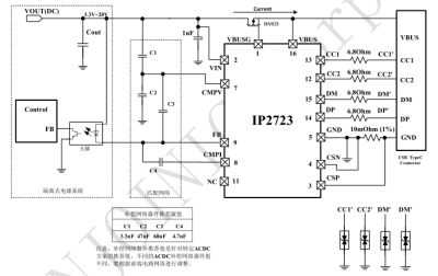
These few caveats are already built into USB-C power supplies. Ultimately, with today’s controller chips, it doesn’t take much to add USB-C output support to a generic power supply during manufacturing – all you really need is a PD controller chip that plugs into the power supply’s feedback line, adds an onboard current sensor, and controls a MOSFET to turn the power on and off, and that chip is responsible for USB-C rules and regulations. Under the control of the FB pin, the PD controller takes over the process of regulating the power supply’s output voltage and generates whatever voltage it may need, within reasonable limits.
Manufacturers have greatly simplified the production of USB-C power supplies by integrating specialized PD controllers. Instead of connecting the feedback signal of your power supply to a conventional voltage divider, you can connect it to a separate module that is responsible for performing all Power Delivery functions. As a result, the power supply becomes universal and ready to use with USB-C devices without additional complications.
Today, for many projects, it is more profitable to buy a ready-made USB-C power supply along with a trigger board than to work with older models of units with cylindrical connectors. This is simpler, cheaper and allows you to easily adjust the voltage for different devices.
Using the correct configuration of the feedback line, you can get any desired voltage, getting rid of restrictions on strange static voltages like 7.5 V or 11 V. This approach allows you to implement PPS functions (AC voltage and DC / AC current), which depends only on the PD controller integrated into the power supply. Modern PD controller chips almost always support PPS, so it’s becoming increasingly easy to find a USB-C charger with this feature.
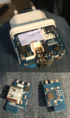
There are numerous chips available on the market that allow you to quickly convert an old or new power supply to USB-C. To do this, you can connect them to a feedback line or use ready-made modules that accept DC current, contain a PD controller and a voltage converter (buck or even buck/boost). Such modules generate all the voltages required for USB-C, making the upgrade process as convenient as possible.
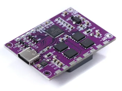
These modules are the opposite of PD trigger modules. Instead of getting DC power from a USB-C PD port, they allow you to create a PD port from a DC source by adding a step-down or step-up voltage conversion stage. This may slightly reduce efficiency compared to direct conversion, but it still provides a great result. Such boards are easy to find on Aliexpress, and they can be distinguished from PD trigger modules by the presence of a large inductor, which is a mandatory component for the operation of these boards.
To find the modules you need, just search for “PD charger module” and check the image for the presence of inductors. One exception may be LiIon chargers with USB-C PD input, but they are easy to filter out by paying attention to the mention of lithium-ion batteries in the product descriptions.
If you need a fast USB-C output and do not have time to wait for delivery from Aliexpress, you can use a USB-C car charger for the cigarette lighter. The main thing is that it supports an output voltage higher than 5 V (for example, 15 W). Such devices are often labeled as those that support higher voltages on USB-C, and they are easy to find on sale. In essence, these are the same PD modules, but they are integrated into the body of a car charger that connects to a 12 V or 24 V voltage source.

Both the cigarette lighter adapter and the Aliexpress options are technologically very similar to the native USB-C PSU option – you get a buck/boost converter with the same chip that plugs into its FB signal, or even a universal chip that does everything for you if you just give it an inductor and a few other parts. But if 5V or 20V is all that’s available in your use case, you can make it even easier!
If you think a 20V power supply can be easily plugged into USB-C without any additional hassle, or if you want to avoid the efficiency loss due to conversion, there is an easy way to create a basic USB-C power supply. Technically, you can limit its output to just 5V and 20V by switching the voltage using field-effect transistors. If the device does not support the 20V profile, it simply will not request that voltage, making this approach ideal for laptops. However, this can make it difficult to charge devices like the Nintendo Switch or smartphones that typically operate at 5V or other voltages.
Interestingly, even voltages not specified by the USB-C standard, such as 12V, are widely used in many power supplies. This is because many Power Delivery controllers are already programmed to operate at 12V, even though it is not an official profile. The tradition of supporting 12V is so widespread that it has become the basis for many breakout boards.
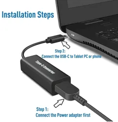
An example of this approach can be found at Dell. They have released an adapter that allows you to convert a standard laptop power supply into a USB-C charger that operates at 5V and 20V, using field effect transistors to switch between voltages. Such adapters, which can be found on Aliexpress or at Dell, have become a great source of inspiration for creating your own USB-C power supplies. This approach is simple, effective, and has proven to be reliable in practice.
To create a power adapter that converts a DC source to a USB-C power supply, you can implement a device that can interface with USB-C devices and provide high-voltage output when needed. Such an adapter will be efficient, easy to modify, and will become a useful educational tool.
The main step is to provide an output voltage of 5 V with a specified current. For a basic implementation, 500 mA at 5 V is enough, which allows you to use a less powerful step-down regulator. For example, you can use the AP63200 switching regulator, which supports an output voltage of 5 V and a current of up to 2 A, operating with an input voltage of 20 V. This allows you to stably supply the basic needs of USB-C devices.
The next steps involve integrating a Power Delivery (PD) chip, which will provide the ability to switch to high voltages when requested by the connected device. This approach allows you to create an adapter that complies with USB-C standards and is suitable for powering or charging a wide range of devices.
To create a power adapter that meets USB-C standards, it is important to ensure stability and safety when working with high voltages. In particular, 20 V must be sufficiently “clean” with minimal noise, as the USB-C standard imposes strict requirements on voltage quality. The best choice in this case is to use OEM power supplies from HP, Dell or Lenovo. They provide high quality and reliability compared to cheap third-party counterparts.
An important aspect is to check the capacity of your power supply. USB-C devices rely on accurate information about the available current. For example, if the power supply is capable of delivering a maximum of 5 A, but the adapter reports incorrect data to the device, this can cause an overload and activate protection. OEM power supplies from the HP/Dell/Lenovo triad usually have a mechanism for transmitting data about the consumed current, which allows you to use GPIO and ADC to check the available power.
To smoothly switch between 5V and 20V output voltages, reliable field effect transistors are required. It is important to avoid reverse voltage flow so that 20V does not enter the 5V rail, and also to ensure that the current in the range of 3A – 5A can be handled without overheating. For this, the SI4909DY transistors (a pair of P-FETs in a compact SO8 package) are suitable, which work well with a gate voltage of up to 10V. They can be used separately for 5V and 20V outputs, providing a smooth transition between voltages without losing VCC.
Ensure that 20V is not applied to the 5V rail.
Use the correct gate voltage values for transistors for optimal operation.
Set up the circuit so that the voltage transitions are fast and accurate, without interruptions in the power supply to the devices.
This approach allows you to create an adapter that supports the requirements of the USB-C standard, ensuring stable operation of devices when switching between voltages.
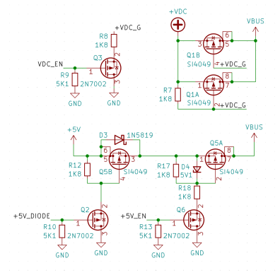
To prevent reverse power supply, an ideal diode circuit can be used, but it is simpler to use a pair of reverse FETs driven by NPN transistors via separate GPIOs. For 20V, two FETs are used in parallel, which allows for lower Rds and heat dissipation. FETs connected in parallel usually balance the current between themselves, ensuring even distribution. For 5V, a pair of SI4909DYs are used in series, while for 20V, transistors are connected in parallel.
The circuit originally involved using a single FET for 20V with additional protection in case of short circuit, but this caused significant heat dissipation. The improvement includes a check of VBUS during startup, so that in case of a short circuit, the power supply turns off and displays an error message.
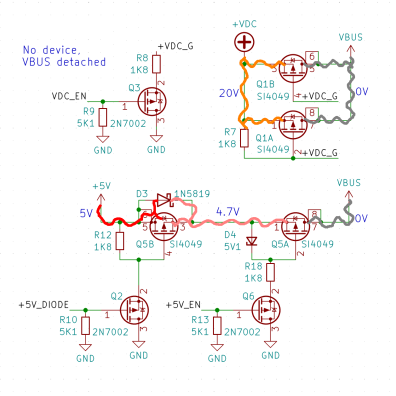
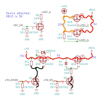
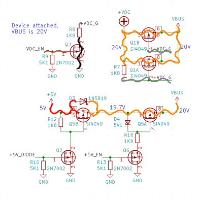
The power supply circuit supports three states: complete absence of voltage on VBUS, VBUS output 5V, and VBUS output 20V. Switching between these states is provided by four field-effect transistors that isolate VBUS from the 5 V and 20 V sources. In 5 V mode, both transistors conduct, and the body diode is used as a backup. For greater reliability, a Schottky diode is added to minimize the voltage drop during the transition period. In 20 V mode, the use of parallel-connected transistors avoids thermal overloads and ensures stability.
The possible leakage of 5 V to the 20 V rail due to the specifics of the power supply does not cause problems, since 5 V is generated from 20 V. This approach avoids stability losses and ensures correct operation of the circuit even under difficult conditions.
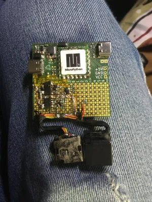
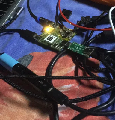
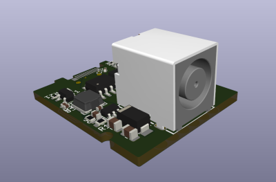
The circuit was implemented on a prototype board for experiments with Power Delivery (PD), and now it remains to write the program code for its operation. As in previous developments, the choice was made in favor of MicroPython, which provides convenience and speed of creating high-level code. The code will be run on the RP2040 controller with the FUSB302 module connected, and the development will be integrated into the existing PD stack, which is gradually expanding.
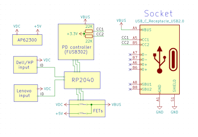
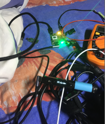
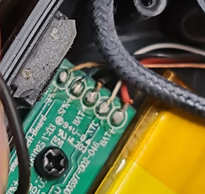
For the 20 V input, it was decided to add two connectors that support three popular types of laptop chargers: a large round plug suitable for Dell and HP, and a square Lenovo plug. These chargers are convenient in that they have a third pin for determining power. For example, Dell uses an EEPROM with a One-Wire interface, HP uses a high pull-up value from VCC, and Lenovo uses a pull-up to GND.
Since older Dell and HP power supplies typically operate at 19V or 18.5V, this will be an interesting test to see how USB-C devices will react to a voltage slightly different from the standard 20V. In case of failure to determine the parameters of the power supply, a default current of 3A will be set, ensuring safe operation. This approach also allows connecting a common drum connector in parallel to provide 60W charging without identification, which can be useful in critical situations, for example, when only a car battery and a pre-programmed board are at hand.
After creating the circuit on the PD experiment protoboard, the next step is to write the software code. The software part will be implemented using MicroPython on the RP2040 in combination with the FUSB302 controller. This code is integrated into a custom PD stack, which is gradually expanded to provide functionality and compliance with standards.
In the basic configuration, VBUS remains disconnected and supplies 5V only when the FUSB302 detects a 5.1kΩ drop in resistance on one of the CC lines. After 5V is activated, the power supply capability advertisement, already mentioned in the Replying PD article, is transmitted. When a request is received from a connected device, the circuit switches to the desired voltage profile, connecting the appropriate bus to the FET.
Current consumption control in this design was decided not to implement, based on the assumption that the connected devices properly regulate consumption. However, it could theoretically be added using a high current sensor, for example from Analog Devices. In this case, this was abandoned, since all available ADC pins on the RP2040 are already used. Two of them are used to detect the capabilities of HP and Lenovo power supplies, one for measuring VBUS, and the fourth for the 20V VIN rail.
In future versions of the design, if more ADCs are needed, an analog multiplexer, such as a 4051, can be integrated to expand the circuit for additional measurements and functions. This will increase flexibility and functionality without significantly complicating the basic design.
The option to check the cable emarker, which indicates whether the cable supports 5A, has been postponed. The emarker is a chip inside the USB-C cable that contains information about its characteristics, including the maximum safe current. According to the standard, the power supply must check for the presence of the emarker before offering a higher current profile, but this feature is not currently implemented.
The presence of a cable mark can be determined by checking the Ra resistor (1 kΩ), which indicates the need for VCONN, which is an indicator of 100W support at 5A. 60W cables are usually not marked unless they are high-speed. Using unmarked cables with this device is not recommended until the emarker check is integrated into the firmware. If there is no emarker, the current should be limited to 3A. You should also make sure that the USB-C connector on the board is rated for 5A, as many only support 3A.
At startup, the code checks the capabilities of the connected power supply. For Dell, this involves reading a single-wire EEPROM, and for Lenovo or HP, determining the resistance between the ID pin and GND or VIN. This can be done using a voltage divider, an ADC, and a Zener diode for protection. If the power supply parameters are not detected, the current is set to 3 A by default, since power supplies for laptops with lower power are rare. Then, a PD profile is generated that contains voltage and current data, and a wait is made for the device to be connected to the USB-C port.
After the device is connected, the USB-C profile is periodically transmitted, and after receiving a Request message from the device, it is analyzed. If the request is confirmed, an Accept message is sent. After receiving a GoodCRC response from the device, 20 V is applied, and a PS_RDY message is sent, signaling that 20 V is available.
This implementation may deviate from the specification, for example, applying voltage after a short delay instead of waiting for a GoodCRC. The “VBUS shutdown” timer, which is a specification requirement, is also not used. Despite such deviations, they do not cause significant problems and ensure stable operation with most devices.
Safety compliance is a must when building a USB-C power supply. Using the FUSB302B PD interface chip includes a feature called “low battery” that automatically applies a 5.1kΩ pull-up to its pins when power is off. This is an important feature, but to operate as a USB-C power supply, you need to disable this pull-up and instead enable the pull-up that signals the 5V/1.5A profile. This switching is part of the USB-C PD analog signaling and is easily implemented through software using the FUSB302.
However, there is a potential problem: if a USB-C power supply or dual port is connected to the adapter when 20V is not yet applied and code is not yet executing, it can cause a boot loop. This situation can be detected in software that allows the adapter to wait until 20V is applied.
To solve this problem, you can use the version of the FUSB302T chip, in which the “low battery” function is not activated. This version is suitable for creating professional USB-C power boards. For the current project, if the FUSB302B chips are already used, they can be replaced with the 302T version. You can determine which chip is used (-B or -T) by reading the FUSB302 version register in the code, which adds convenience to debugging. This approach provides greater stability and flexibility in the implementation of the project.
After removing the 5.1kΩ pull-up, it is necessary to ensure that VBUS returns to 0V to prevent 20V from remaining on the connector after the powered device is disconnected. If 20V remains on VBUS and the device is no longer connected, this can lead to 20V being applied to the pins of another device when connected. The USB-C standard only allows this for 5V, so this scenario must be ruled out. For safety, it is recommended to implement a watchdog timer that returns the system to a safe state in the event of a code failure. Implementing a watchdog timer in MicroPython is an effective solution for such situations.
Overcurrent protection is also an important consideration. To protect against short circuits on the 5V bus, a current-limiting switch, such as the SY6820, can be used, placed immediately before the 5V FET pair. Setting the limit to just above 1.5A will ensure stable operation even if VBUS fails. The new circuit includes this element, while the previous one did not.
Regarding the overcurrent of the DC input, one can consider its limits, but it is usually sufficient to rely on the output current limits of the power supply. Also, if VBUS and VDC are measured and the resistor dividers are accurately calibrated, the current can be estimated through the difference between VBUS and VDC by using the FET as a shunt. If the voltage drop across the FET between VDC and VBUS exceeds a few volts, this is a sign of overload, and in this case it is worth turning it off to protect the system. This approach allows for stable and safe operation of the circuit even in the event of an emergency.
The code to implement USB-C PD behavior is actually not that complicated, especially considering that FUSB302 provides interrupts for USB-C events. The task is to process these interrupts and incoming PD messages in a FIFO. The code snippet that was written allows you to create USB-C PD profiles from a list using a function that converts values to bytes. It is based on the PD profile parsing function from the previous article “Response to PD”, but in the opposite direction: instead of extracting bytes, the function converts values to bytes.
To ensure correctness, each newly created profile is checked through the same parser, and the results are checked for consistency using assert(). Generating PS_RDY and Accept messages is also a fairly simple task due to the presence of a common function that sends any command message. It was created based on the Request function from the previous stages of work.
The power supply behavior cycle code was developed gradually, with constant testing. To test basic scenarios such as connecting, disconnecting, or handling FUSB302 interrupts, a simple USB-C device with 5.1kΩ resistors was used. This minimizes the risk of damage even if 20V is accidentally applied.
One of the first devices to be tested was Pinecil, known for its tolerance to a variety of PD power supplies. Its open-source PD stack is adapted to work with a wide range of non-standard power supplies, making it a great choice for testing devices with potential flaws. Pinecil is also safe for experimentation: it does not fail if 20V is applied to the VBUS, while many laptops may not only not accept this, but may fail in the worst case.
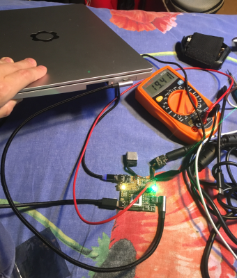
Testing with Pinecil allowed us to verify the basic functionality of the power supply, including the behavior when connecting and disconnecting, sending PD profiles, and their correct recognition. Pinecil’s test functions showed that all profiles generated by the code were processed correctly. The final stage was testing with the Framework laptop, for which the power supply was designed. However, working with it did not go smoothly on the first try, as the PD Framework controllers strictly follow the USB-C specifications, which required additional debugging.
One problem was that the PD advertisement was sent too early after the device was connected. This became apparent when Pinecil took about five seconds to negotiate with the power supply, while a regular charger negotiated in one second. Fixing this delayed the sending of the first advertisement, allowing the laptop to correctly receive the profiles and request 20V. However, after applying 20V to the VBUS, the Framework still disconnected. The problem was that there was not enough delay between sending Accept and applying 20V. After increasing the delay, the power supply started working correctly. Waiting for a GoodCRC response would have been a more accurate solution, but even a simplified approach proved to be effective.
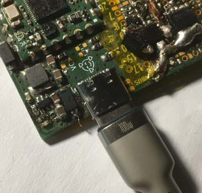
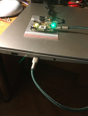
Although careful study of the USB-C specifications and proper implementation of all restrictions could have made the process easier, the results of the power supply turned out to be excellent. Even increasing the current to 5A did not cause any problems when using cables that support 100W. However, some elements are still in the development stage. For example, checking the emarker or the capabilities of the laptop power supply has not yet been implemented, so the PD profiles are hard-coded, instead of dynamically calculated at startup. Despite this, the power supply works stably with the laptop in certain cable and adapter configurations, and the first homemade 100W USB-C power supply copes with the task perfectly.
Some projects inspired by this scheme have already turned it into functional boards thanks to the efforts of friends and colleagues. For example, [Wificable] created an expansion board for the Framework laptop that allows you to use Dell and HP power supplies as USB-C chargers. In the future, such a board may receive support for additional features, such as MagSafe, which opens up even more possibilities for integration.
This project has shown impressive results: it allowed you to reuse a large number of old power supplies, revealed an unexpected function of the Framework PD controller, and became the basis for creating a simple and efficient USB-C power supply, which can also be adapted to work with LiIon batteries. It seems that this board itself will become the basis for many other interesting developments.
As for cables, USB-C is becoming a universal standard, and this is natural, because they are convenient to use in various projects due to their high manufacturing quality, availability and relatively low price. In comparison, while USB 3.0 cables are also manufactured to high standards and can even be used for PCIe connections, USB-C cables surpass them in many ways.
It’s worth taking a closer look at the capabilities of USB-C cables. Whether it’s a simple USB 2.0 CC cable to power an automotive device or a state-of-the-art 240W Thunderbolt cable with high-speed data transfer support, USB-C can meet most needs. Are you looking for a cable that you can customize for your own circuits, or want to provide a high-speed connection for serious tasks? This standard offers versatility and functionality for any engineering challenge.
The least interesting are USB-A to USB-C cables. They are the equivalent of a microUSB to USB-A cable, except that there is a resistor on the USB-C plug connected from VBUS to one of the CC pins. That’s it. The cable is four-conductor, not much new really. Save these cables for all the devices built without 5.1kΩ resistors.
Now, the USB-C to USB-C cable – let’s say 60W max, the default USB-C cable capability. If your cable says less than 60W, say “2A” or “15W”, that’s a lie – it can handle 60W without a problem, all USB-C to C cables can handle 60W. This cable is also cool – for one it has five conductors; GND, VBUS, D+, D- and CC. Two of them (GND and VBUS) are guaranteed to be thick enough to carry 3A without significant voltage drop, if any at all!
You need a cable for your project, and since USB-C cables are now ubiquitous, it’s only natural to want to reuse them for your evil schemes. Have you ever seen USB 3.0 cables being used for PCIe connections? That’s because USB 3.0 cables are built to a pretty high standard, both the connectors and cables are easy to find, and they’re cheap. Well, USB-C cables beat USB 3.0 cables in every way possible.
Let’s take a closer look at reusing a USB-C cable and see what exactly you’ll get when you buy either a gas station USB 2.0 CC cable or the most fancy, full-featured 240W Thunderbolt cable money can buy. Looking for a cable to cut up or something to pass along a seriously high-speed connection? You’ve come to the right place.
The least interesting are USB-A to USB-C cables. They are the equivalent of a microUSB to USB-A cable, except that there is a resistor on the USB-C plug connected from VBUS to one of the CC pins. That’s it. The cable is four-conductor, not much new really. Save these cables for all the devices built without 5.1kΩ resistors.
Now, the USB-C to USB-C cable – let’s say 60W max, the default USB-C cable capability. If your cable says less than 60W, say “2A” or “15W”, that’s a lie – it can handle 60W without a problem, all USB-C to C cables can handle 60W. This cable is also cool – for one it has five conductors; GND, VBUS, D+, D- and CC. Two of them (GND and VBUS) are guaranteed to be thick enough to handle 3A without much voltage drop, if any!
What does this mean? If you need a five-conductor cable to hook up your headphones and you want something sturdy, a USB-C cable is probably your best bet – and you have a ton of choices. You’ll inevitably end up with a bunch of broken USB-C cables, which means you’ll never run out of 5-conductor cables – a cable that has always been a rarity, unless you’re stealing headphone cables for your projects.
What about cables from 100 to 240W? There is good news and bad news. The good news is that the cable probably has six wires. One extra wire is for VCONN – power for the emarker chip inside the cable plug, a memory chip that can be read via the CC line, telling the power supply whether the cable is actually capable of delivering more than 5A – needed for the 61W to 240W range.
The bad news is that there could still be five wires if the cable is built using the alternative scheme of two markers, one per plug. Then there would be no VCONN wire and there is no way to tell until you cut the wire, so if you are looking for a six-wire cable you may have to try a few different cables. Also, the VCONN wire doesn’t connect two prongs together – it’s insulated on one end, so don’t expect it to help if you use USB-C connectors instead of cutting the cable.
Now, you don’t always want to cut the cable – you can use USB-C connectors and apply your own five-wire design to them. The idea is to use USB-C cables for 3D printers. This makes sense – these cables can handle 60W of power without breaking a sweat, and you could probably do a bit more. Feed the extruder power to the VBUS and GND pins, and use the remaining three wires for the thermistor and limit switch. But the mechanical elements of the cable and the socket can be a deal-breaker. If your extruder power cable vibrates from the socket, you could end up with a high-resistance, high-current contact on your hands – a recipe for molten plastic and possibly flames. Try at your own risk!
You also won’t be able to make such a cable compliant with the reuse standard, and such a port won’t be safe for any USB-C devices someone might plug into it, so please mark it accordingly.
What about setting an arbitrary voltage on VBUS without PD negotiation? Again, it won’t be compliant unless you really put in the effort – mark your jury-rigged sockets and cables accordingly, or they’ll eat your devices for breakfast. Also, the SPR cables (100W) contain 30V 10nF capacitors on each end of the plug, and the EPR cables contain 63V capacitors – reach these limits at your own risk, these capacitors have been known to fail due to short circuits.
Another factor is if you decide to go for the 48V/5A target, bypassing the USB-C standard, because supporting 48V is not as simple as connecting 48V to VBUS. If you just connect 48V to the VBUS pins, you really want to figure out spark management so that a sudden cable disconnect doesn’t burn up the plug or the socket or both – PD has ways to handle this, but they require you to actually implement PD, specifically EPR, which provides a bunch of safety safeguards over exceeding the 20V limit.
That’s about it when it comes to reusing the cheapest types of USB-C cables – you get extra wire compared to previous USB standards, it can handle a bit more power, and you can even use USB-C connectors. However, it will kill your devices if you’re not careful, and you need to be extra careful if you go above 25V or so. What if you want to get more wires and instead pull out a few differential pairs?
Full-featured USB-C cables and connectors are really great for high-speed communication. They’re built to a solid standard, with proper impedance control, shielding, and a modern understanding of digital transmission standards. What exactly do you get from a full-featured USB-C cable?
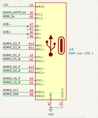
The short answer is: you get six differential pairs and one single-ended wire (CC), in addition to VBUS and GND. You might want to keep GND stable here and maybe not mess around with VBUS too much. There’s a lot you can do with those six differential pairs – two USB3 ports, or a PCIe x2 connection, or two SATA, or HDMI, or CSI/DSI. You can even use Ethernet if you really want to – just don’t expect galvanic isolation to work.
There are nuances, of course! Have you ever seen a teardown or x-ray of a fancy full-featured cable? There are usually all sorts of chips inside each plug. The first is the emarker chip, which is interesting to remember. For starters, this will introduce some ESD diodes between GND and CC – be careful not to drop CC below 0V or above 5V.
The second type of chip is the re-signal driver, which is used in active cables. You have to power these re-drivers via VBUS or VCONN, just like emarkers. If you don’t, your high-speed lines may simply not respond to any high-speed signal you apply to the pins.
What about rotation? This is tricky – unless your signal is very similar to USB3/DisplayPort/Thunderbolt, you may not be able to find a suitable multiplexer chip to rotate your signals. So you probably want to stick to a single rotation and connect the signals straight through. Then if you connect the cable in an unexpected way it won’t work, so you should probably consider using the CC pin or the two SBU pins to light up the LEDs. showing if you’re okay or if you should unplug the cable, turn it around and plug it back in like the good old days.
There’s an important thing to keep in mind when working with USB-C cables: they connect TX on one end to RX on the other and vice versa. This is convenient for PCIe use, as the pair names change automatically. However, for other types of signals this can be a problem. For example, RX1 won’t connect to RX1 on the opposite end, but will connect to TX1. Accordingly, you should take this into account when designing and adjust the circuit according to the specifics of the cable.
For active cables, the situation is more complicated. Due to a lack of understanding of the inner workings of such cables, it is difficult to say for sure whether active reboot chips will restrict certain types of signals that are not compliant with USB3, DisplayPort, or Thunderbolt standards. This remains an open question that may require additional research and testing.
That’s the basics of what you should know before you try to reuse a USB-C cable, no matter how complicated it is. However, here’s an extra hack before we’re done!
Only one USB2 pair is actually connected to the end of a USB-C cable – the pair on the same side as the CC pin. We assume this was originally done to avoid issues with PCB headers and cable plugs, and to comply with standards like VirtualLink. Unfortunately, we never got around to VirtualLink cables that would allow us to use seven differential pairs at once, but there’s one more hack we’re working on anyway!
What does this mean for you? If you use two USB2 2:1 class multiplexers, you can get two extra differential signals out of a fully compliant USB connector, and they won’t even interfere with standards-compliant cables. Use this for SWD, JTAG, or whatever, with your signals coming through a dedicated plug – just make sure you dutifully switch the multiplexers depending on the cable orientation, then you can have your USB2 cake and eat it too.