
26.08.2024
3 min
1422

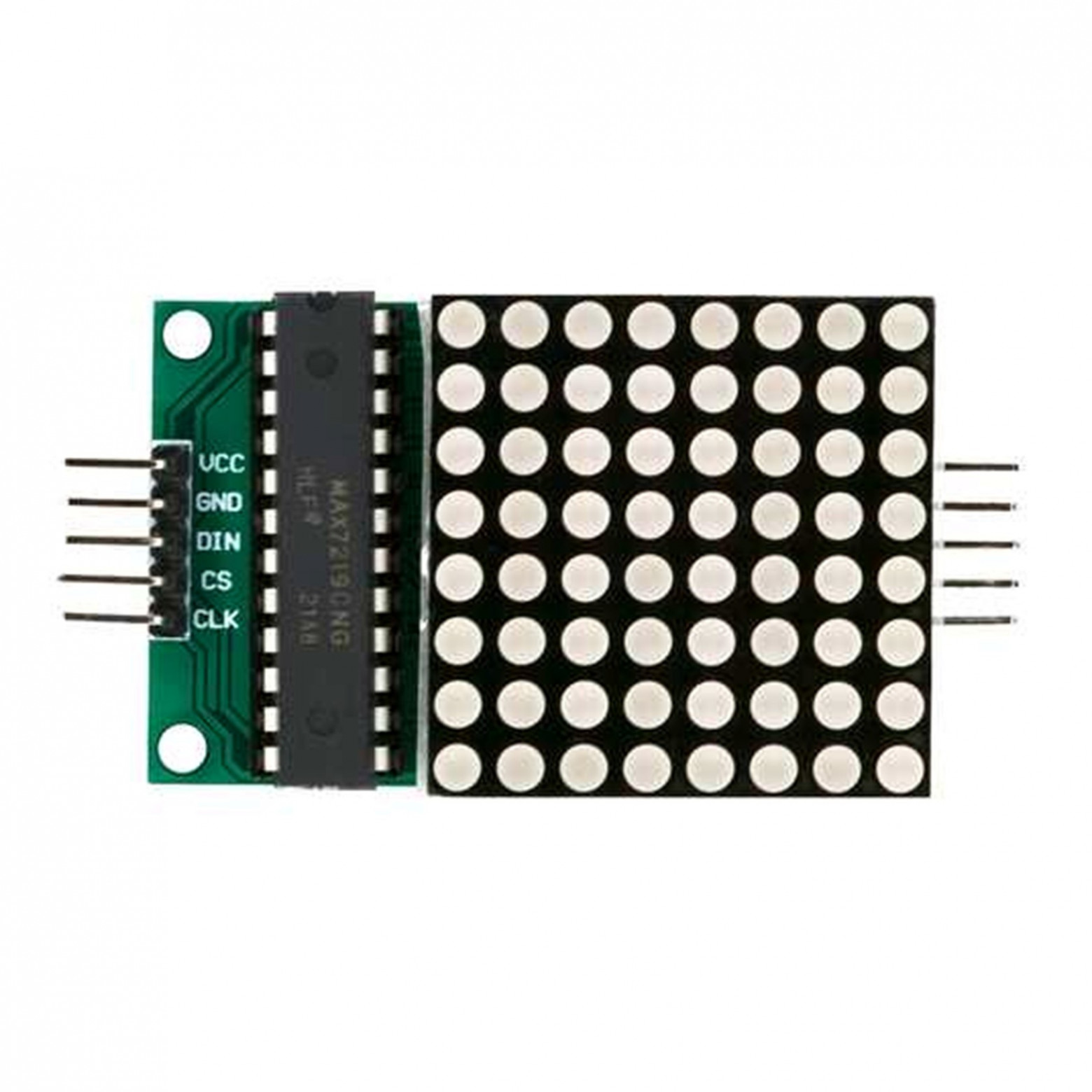
Learn how to create hardware-independent libraries for microcontrollers to make them as easy as possible to reuse across platforms without the need for deep code changes. This article provides concrete examples, including work with the STM32 and MAX7219, to help you better understand the approach to building universal microcontroller solutions.

The article explains how to develop hardware-independent libraries for microcontrollers so that the same library can be used on different platforms without having to modify the code for a specific microcontroller. The process of interaction with digital microcircuits through UART, SPI, I2C and other interfaces is described. The creation of such libraries consists in abstraction from specific frameworks (STM32-HAL, ESP-IDF, Arduino, etc.), which allows the use of code on different microcontrollers. An example of work with the MAX7219 microcircuit and LED matrices based on it is considered.
Note: The code in the section is provided for STM32 and taken from the GitHub repositories.
Often, when searching for ready-made libraries on the Internet, you can find such examples, where #define directives are used in the header files (.h) for HAL-handlers, pins and ports of the microcontroller.
#define NUMBER_OF_DIGITS      8
#define SPI_PORT              hspi1
extern SPI_HandleTypeDef      SPI_PORT;
#define MAX7219_CS_Pin        GPIO_PIN_6
#define MAX7219_CS_GPIO_Port  GPIOA
…
void max7219_Init();
void max7219_SetIntensivity(uint8_t intensivity);
…
void max7219_SendData(uint8_t addr, uint8_t data);
…
In .c files, HAL headers for a specific stone are included, and accordingly the entire library works on HAL.
#include "stm32f1xx_hal.h"
#include <max7219.h>
…
void max7219_Init() {
    max7219_TurnOff();
    max7219_SendData(REG_SCAN_LIMIT, NUMBER_OF_DIGITS - 1);
    max7219_SendData(REG_DECODE_MODE, 0x00);
    max7219_Clean();
}

void max7219_SetIntensivity(uint8_t intensivity) {
    if (intensivity > 0x0F)
        return;

    max7219_SendData(REG_INTENSITY, intensivity);
}
…
void max7219_SendData(uint8_t addr, uint8_t data) {
    HAL_GPIO_WritePin(MAX7219_CS_GPIO_Port, MAX7219_CS_Pin, GPIO_PIN_RESET);
    HAL_SPI_Transmit(&hspi1, &addr, 1, HAL_MAX_DELAY);
    HAL_SPI_Transmit(&hspi1, &data, 1, HAL_MAX_DELAY);
    HAL_GPIO_WritePin(MAX7219_CS_GPIO_Port, MAX7219_CS_Pin, GPIO_PIN_SET);
}
Cons of this approach:
The library can only work with one connected module.
Dependency on HAL.
When connecting the library to your project, you need to go into the library files and configure them for yourself.
It will be problematic to transfer the library to microcontrollers of other manufacturers.
#define REG_NOOP         0x00
#define REG_DIGIT_0      0x01
#define REG_DIGIT_1      0x02
#define REG_DIGIT_2      0x03
#define REG_DIGIT_3      0x04
#define REG_DIGIT_4      0x05
#define REG_DIGIT_5      0x06
#define REG_DIGIT_6      0x07
#define REG_DIGIT_7      0x08
#define REG_DECODE_MODE  0x09
#define REG_INTENSITY    0x0A
#define REG_SCAN_LIMIT   0x0B
#define REG_SHUTDOWN     0x0C
#define REG_DISPLAY_TEST 0x0F
Next, we will create pointers to functions for working with SPI:
typedef void (*SPI_Transmit)(uint8_t* data, size_t size);
typedef void (*SPI_ChipSelect)(uint8_t level);
In the main program, it is necessary to independently implement such functions as SPI_Transmit, which will be responsible for transferring an array of data bytes through the selected SPI, and SPI_ChipSelect, which will change the state of the CS pin depending on the level parameter. After that, you should define a structure for describing the microcircuit, which will allow you to manage it in the program.
typedef struct{
    SPI_Transmit spiTransmit;
    SPI_ChipSelect spiChipSelect;
}MAX7219_st;
In this case, there will be enough fields that accept pointers to SPI functions. The matrix data buffer will be described at the next level of abstraction. Finally, let’s define the main functions:
void MAX7219_Init(MAX7219_st* max7219, SPI_Transmit spiTransmit,
                  SPI_ChipSelect spiChipSelect);
void MAX7219_WriteReg(MAX7219_st* max7219, MAX7219_Register_t reg, uint8_t data);
In the MAX7219_Init initialization function, we will pass a pointer to the MAX7219_st structure and pointers to SPI functions, which we will describe in the main program. Let’s go to the max7219.c file.
#include "max7219.h"
void MAX7219_Init(MAX7219_st* max7219, SPI_Transmit spiTransmit,
SPI_ChipSelect spiChipSelect){
max7219->spiTransmit = spiTransmit;
max7219->spiChipSelect = spiChipSelect;
}
void MAX7219_WriteReg(MAX7219_st* max7219, MAX7219_Register_t reg, uint8_t data){
if(max7219->spiChipSelect != NULL){
max7219->spiChipSelect(0);
}
max7219->spiTransmit(®, 1);
max7219->spiTransmit(&data, 1);
if(max7219->spiChipSelect != NULL){
max7219->spiChipSelect(1);
}
}
In the MAX7219_Init function, function pointers are assigned to the fields of the transferred structure. The MAX7219_WriteReg function calls functions to transfer data via SPI. If the microcontroller supports automatic switching of the CS pin, it is possible not to switch it in software and pass NULL as the spiChipSelect parameter during initialization. This completes the implementation of the basic driver. Next, it is planned to develop a higher-level logic for working with an LED matrix that uses this driver.
At this stage, we will create a library that will provide a convenient interface for the developer to work with the LED matrix. Let’s create a pair of MatrixLed.h and MatrixLed.c files. In MatrixLed.h, we will connect the previously created max7219 driver and describe the structure of the matrix module.
#include "max7219.h"
#define MATRIX_SIZE 8

typedef struct{
    MAX7219_st max7219;
    uint8_t displayBuffer[MATRIX_SIZE];
}MatrixLed_st;
The MatrixLed_st structure contains an instance of the MAX7219_st driver and an image buffer on the matrix.
Next, we will announce the following functions:
void MatrixLed_Init(MatrixLed_st* matrixLed, SPI_Transmit spiTransmit,
                    SPI_ChipSelect spiChipSelect);
void MatrixLed_SetPixel(MatrixLed_st* matrixLed, uint8_t x, uint8_t y,
                        uint8_t state);
void MatrixLed_DrawDisplay(MatrixLed_st* matrixLed);
A pointer to the MatrixLed_st structure and functions for working with SPI are passed to the MatrixLed_Init function. The MatrixLed_SetPixel function allows you to set the state of an individual pixel by its coordinates, but does not change the state of the LEDs immediately. For this, a separate function MatrixLed_DrawDisplay is used, which updates the state of all LEDs and provides visualization of changes on the matrix. This approach separates the logic of changing pixel state and updating the display for more flexible operation.
Let’s go to MatrixLed.c.
void MatrixLed_Init(MatrixLed_st* matrixLed, SPI_Transmit spiTransmit,
                    SPI_ChipSelect spiChipSelect){
    matrixLed->max7219.spiTransmit = spiTransmit;
    matrixLed->max7219.spiChipSelect = spiChipSelect;

    MAX7219_WriteReg(&matrixLed->max7219, REG_NOOP, 0x00);
    MAX7219_WriteReg(&matrixLed->max7219, REG_SHUTDOWN, 0x01);
    MAX7219_WriteReg(&matrixLed->max7219, REG_DISPLAY_TEST, 0x00);
    MAX7219_WriteReg(&matrixLed->max7219, REG_DECODE_MODE, 0x00);
    MAX7219_WriteReg(&matrixLed->max7219, REG_INTENSITY, 0x00);
    MAX7219_WriteReg(&matrixLed->max7219, REG_SCAN_LIMIT, 0x07);

    MAX7219_WriteReg(&matrixLed->max7219, REG_DIGIT_0, 0x00);
    MAX7219_WriteReg(&matrixLed->max7219, REG_DIGIT_1, 0x00);
    MAX7219_WriteReg(&matrixLed->max7219, REG_DIGIT_2, 0x00);
    MAX7219_WriteReg(&matrixLed->max7219, REG_DIGIT_3, 0x00);
    MAX7219_WriteReg(&matrixLed->max7219, REG_DIGIT_4, 0x00);
    MAX7219_WriteReg(&matrixLed->max7219, REG_DIGIT_5, 0x00);
    MAX7219_WriteReg(&matrixLed->max7219, REG_DIGIT_6, 0x00);
    MAX7219_WriteReg(&matrixLed->max7219, REG_DIGIT_7, 0x00);
}
In the initialization function, we accept the pointers of the SPI operation functions, configure the module and turn off all the LEDs on the matrix.
void MatrixLed_SetPixel(MatrixLed_st* matrixLed, uint8_t x, uint8_t y,
                        uint8_t state){
    if(state){
        matrixLed->displayBuffer[y] |= (0x80 >> x);
    }
    else{
        matrixLed->displayBuffer[y] &= ~(0x80 >> x);
    }
}
MatrixLed_SetPixel sets the necessary bits in the matrix image buffer according to the transferred coordinates.
void MatrixLed_DrawDisplay(MatrixLed_st* matrixLed){
    MAX7219_WriteReg(&matrixLed->max7219, REG_DIGIT_0,
                        matrixLed->displayBuffer[0]);
    MAX7219_WriteReg(&matrixLed->max7219, REG_DIGIT_1,
                        matrixLed->displayBuffer[1]);
    MAX7219_WriteReg(&matrixLed->max7219, REG_DIGIT_2,
                        matrixLed->displayBuffer[2]);
    MAX7219_WriteReg(&matrixLed->max7219, REG_DIGIT_3,
                        matrixLed->displayBuffer[3]);
    MAX7219_WriteReg(&matrixLed->max7219, REG_DIGIT_4,
                        matrixLed->displayBuffer[4]);
    MAX7219_WriteReg(&matrixLed->max7219, REG_DIGIT_5,
                        matrixLed->displayBuffer[5]);
    MAX7219_WriteReg(&matrixLed->max7219, REG_DIGIT_6,
                        matrixLed->displayBuffer[6]);
    MAX7219_WriteReg(&matrixLed->max7219, REG_DIGIT_7,
                        matrixLed->displayBuffer[7]);
}
MatrixLed_DrawDisplay writes data from the buffer to the microcircuit registers.
To implement the same algorithm on different microcontrollers, we light the LEDs diagonally with a period of 1 second, starting from the lower left corner to the upper right. The main difference between the examples will be the implementation of SPI functions specific to each microcontroller. Despite different hardware platforms, the logic of the code remains practically the same. The results of the demonstration will be shown in the corresponding section (item 6).
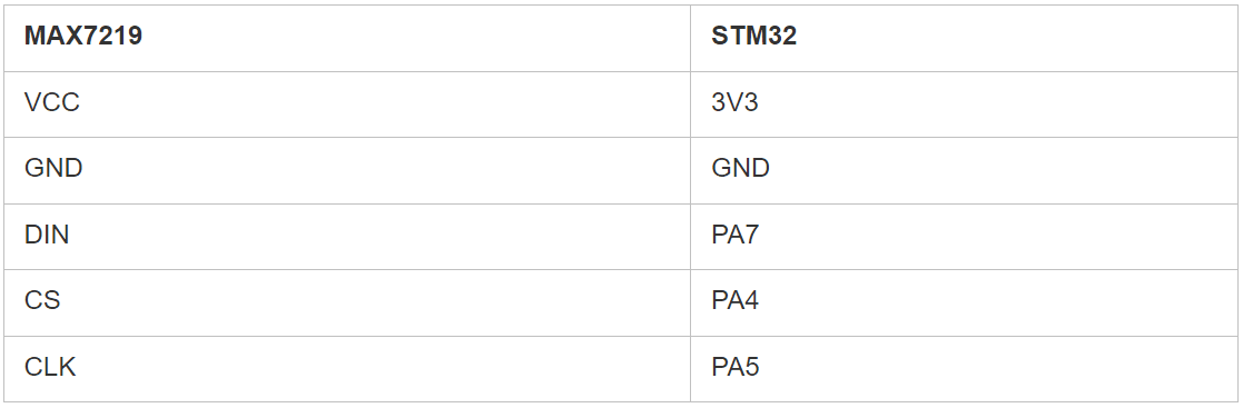
For an example, we will use a debugging board based on STM32F401. Let’s create a new project in CubeIDE and configure SPI.
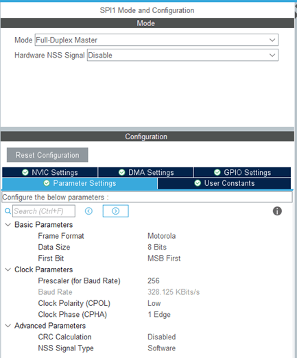
Crucifixion:
Next, in main.c, we will describe the following code fragment:
#include "main.h"
#include "MatrixLed.h"

SPI_HandleTypeDef hspi1;

MatrixLed_st matrixLed;

void MatrixLed_SPI_ChipSelect (uint8_t level){
    HAL_GPIO_WritePin(SPI1_CS1_GPIO_Port, SPI1_CS1_Pin, level);
}
void MatrixLed_SPI_Transmit (uint8_t* data, size_t size){
    HAL_SPI_Transmit(&hspi1, data, size, 10);
}

int main(void)
{
    MatrixLed_Init(&matrixLed, MatrixLed_SPI_Transmit, MatrixLed_SPI_ChipSelect);

        while (1)
        {
            uint8_t x = 0;
            uint8_t y = 0;
            while(x < MATRIX_SIZE && y < MATRIX_SIZE){
            MatrixLed_SetPixel(&matrixLed, x, y, 1);
            MatrixLed_DrawDisplay(&matrixLed);
            HAL_Delay(1000);
            MatrixLed_SetPixel(&matrixLed, x, y, 0);
            MatrixLed_DrawDisplay(&matrixLed);
            x++;
            y++;
        }
    }
}
MatrixLed_SPI_ChipSelect sets the desired level on the CS pin according to the passed parameter. MatrixLed_SPI_Transmit sends the transmitted SPI buffer. Pointers to these functions are passed to MatrixLed_Init. In the cycle, the LEDs light up according to the problem set in the example.
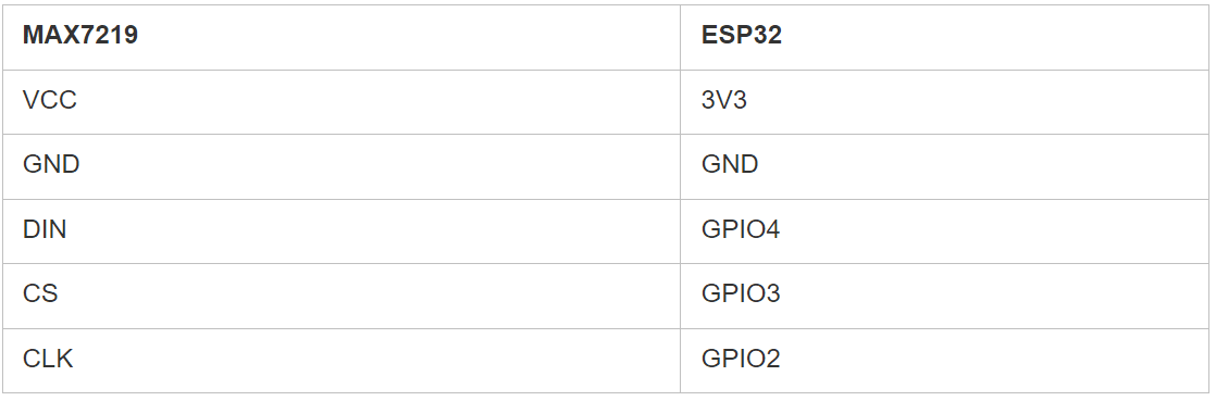
For an example, we will use a debugging board based on ESP32C3. Let’s create a new project in ESP-IDE, and configure SPI.
Crucifixion:
Main.c code:
#include <stdio.h>
#include "freertos/FreeRTOS.h"
#include "freertos/task.h"
#include "driver/spi_master.h"
#include "driver/gpio.h"
#include "MatrixLed.h"

#define MOSI_PIN    GPIO_NUM_4
#define CS_PIN      GPIO_NUM_3
#define CLK_PIN     GPIO_NUM_2

spi_device_handle_t spi2;

MatrixLed_st matrixLed;

void MatrixLed_SPI_Transmit(uint8_t* data, size_t size){
    spi_transaction_t transaction = {
        .tx_buffer = data,
        .length = size * 8
    };

    spi_device_polling_transmit(spi2, &transaction);
}

static void SPI_Init() {
    spi_bus_config_t buscfg={
        .miso_io_num = -1,
        .mosi_io_num = MOSI_PIN,
        .sclk_io_num = CLK_PIN,
        .quadwp_io_num = -1,
        .quadhd_io_num = -1,
        .max_transfer_sz = 8,
    };

    spi_device_interface_config_t devcfg={
        .clock_speed_hz = 1000000,
        .mode = 0,
        .spics_io_num = CS_PIN,
        .queue_size = 1,
        .flags = SPI_DEVICE_HALFDUPLEX,
        .pre_cb = NULL,
        .post_cb = NULL,
    };

    spi_bus_initialize(SPI2_HOST, &buscfg, SPI_DMA_CH_AUTO);
    spi_bus_add_device(SPI2_HOST, &devcfg, &spi2);
};

void app_main(void)
{
    SPI_Init();
    MatrixLed_Init(&matrixLed, MatrixLed_SPI_Transmit, NULL);

    while (1) {
        uint8_t x = 0;
        uint8_t y = 0;
        while(x < MATRIX_SIZE && y < MATRIX_SIZE){
            MatrixLed_SetPixel(&matrixLed, x, y, 1);
            MatrixLed_DrawDisplay(&matrixLed);
            vTaskDelay(1000/portTICK_PERIOD_MS);
            MatrixLed_SetPixel(&matrixLed, x, y, 0);
            MatrixLed_DrawDisplay(&matrixLed);
            x++;
            y++;
        }
    }
}
Crucifixion:
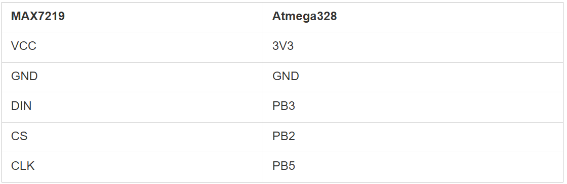
Main.c code:
#include "MatrixLed.h"

MatrixLed_st matrixLed;

void MatrixLed_SPI_ChipSelect(uint8_t level){
  if(!level){
    PORTB &= ~(0x04);
  }
  else{
    PORTB |= 0x04;
  }
}
void MatrixLed_SPI_Transmit(uint8_t* data, size_t size){
  for(size_t i = 0; i < size; i++){
    SPDR = data[i];
    while(!(SPSR & (1 << SPIF)));
  }
}

void SPI_Init(){
  DDRB = (1 << DDB2)|(1 << DDB3)|(1 << DDB5);
  SPCR = (1 << SPE)|(1 << MSTR)|(1 << SPR0);
}

void setup() {
  SPI_Init();
  MatrixLed_Init(&matrixLed, MatrixLed_SPI_Transmit, MatrixLed_SPI_ChipSelect);
}


void loop() {
  uint8_t x = 0;
  uint8_t y = 0;
  while(x < MATRIX_SIZE && y < MATRIX_SIZE){
    MatrixLed_SetPixel(&matrixLed, x, y, 1);
    MatrixLed_DrawDisplay(&matrixLed);
    delay(1000);
    MatrixLed_SetPixel(&matrixLed, x, y, 0);
    MatrixLed_DrawDisplay(&matrixLed);
    x++;
    y++;
  }
}
The implementation of the MatrixLed_SPI_ChipSelect and MatrixLed_SPI_Transmit functions is similar to the STM32 example. The task implementation code has changed, except for the delay function.
This approach makes it easy to use the same library on different hardware platforms without having to change the library itself. It is only necessary to describe a few functions to interact with the interface in the project, taking into account the specifics of the platform. The driver repository is available at the link: https://github.com/krllplotnikov/MAX7219.
If you have any problems, you can contact us at [email protected].