
How to get started with STM32: a complete guide for those already familiar with Arduino

Programmable RGB LEDs appeared relatively recently. A pioneer in this area is considered to be the Chinese company WorldSemi, which released the WS2811 LED in 2013. But to be more precise, WS2811 was a microchip placed next to RGB LEDs. One such microchip could control three RGB LEDs via a simple communication protocol. In later versions — WS2812 — this microchip was reduced so much that it could be placed directly inside each individual LED. Today, there are already many models of such LEDs, commonly known as neopixels — a term popularized by Adafruit Industries.
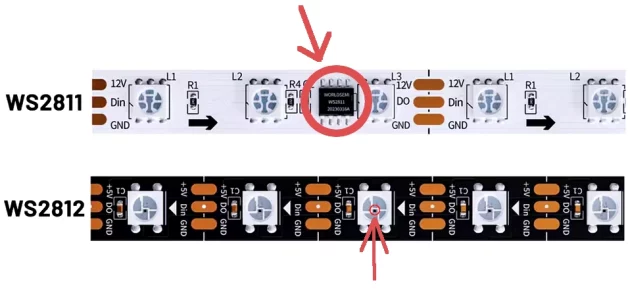
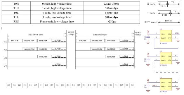
Usually, neopixels are placed into so-called RGB LED strips, where they are connected sequentially one after another. Each LED, thanks to the built-in controller, can be turned on independently from the others. This is achieved through a specific control protocol using only one data line. Bits of data with encoded color values to be turned on are transmitted via this line — 8 bits (0–255 shades) per color. That means 24 bits total for the 3 colors of one RGB (Red, Green, Blue) LED. Each neopixel has 4 pins: VDD and GND for power, and DIN and DOUT for receiving and transmitting the PWM control signal. The DIN input of the next neopixel is connected to the DOUT output of the previous one, forming a chain. In this way, each neopixel receives 24 bits of signal through DIN, and if more data follows, it passes these received 24 bits further in sequence to the next neopixel via DOUT, and starts receiving the next 24 bits itself. This continues until it receives a Reset signal, which means that data transmission is finished and it’s time to display the received colors. The Reset signal is just a low signal lasting 280+ microseconds.
The control signal that encodes the bits is a PWM signal, where each bit is a pulse with a duration of either 1/4 or 3/4 of the period. A 3/4 duty cycle period means 1, and a 1/4 filled period means 0.
Here is what the protocol looks like on a logic analyzer diagram for two WS2812B LEDs connected in series:
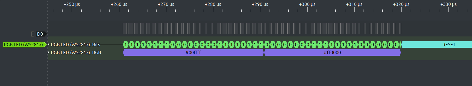
As shown on the diagram, each LED receives 24 bits. The first LED in our improvised strip was set to color #00ffff, and the second — #ff0000. And at the end we see a low Reset signal. One important nuance is that bits are actually transmitted not in RGB, but in GRB order. That is, the first 8 bits transmitted for each LED are for the green color.

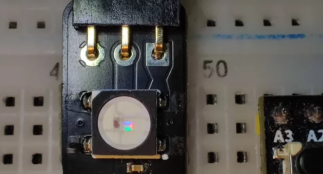
Let’s assemble a test stand and try to implement the neopixel control protocol. We will need:
According to the WS2812B datasheet, the power supply voltage should be 3.7V–5.3V, which is slightly more than the 3.3V provided by the STM32G030 board. So ideally we should power the neopixel separately with 3.7V, but in practice I tested that 3.3V is sufficient for a few LEDs connected in series.
Although the neopixel is technically connected to 5V, in reality it receives 3.3V, because 3.3V goes to the microcontroller itself and to the step-down regulator. The regulator works in such a way that if voltage is applied from its “lower” side, the same voltage appears on the “higher” side. So both sides of the regulator have 3.3V, which suits our needs.
In previous articles, we reviewed timers and several use cases. One of them was an example using PWM (Pulse Width Modulation). There, the timer generated the PWM signal itself, and in the while loop we just changed the pulse width from 0 to 100%. This allowed smooth control over LED brightness. To control neopixels, we will also use the timer’s PWM. However, this time, the duration of PWM pulses will be transferred to the timer by DMA. DMA — Direct Memory Access — is a hardware peripheral of the microcontroller, just like timers or GPIO. DMA helps offload the microcontroller core from data transfer tasks: from one memory area to another, or from memory to a register and back. In our case, we need to transfer data from memory (an array) to the CCR (Capture/Compare Register) of our timer, which is responsible for the pulse widths of the PWM signal.
The control signal for neopixels is quite high-frequency: in older models 0.8 MHz (1.25 µs), in newer ones it can be up to 1 MHz (1 µs). That means if the core had to send data to the CCR register directly, it would be heavily loaded and would not have enough resources left for more meaningful tasks. Instead, we will prepare an array with PWM duty cycle values, and DMA will transfer this data to the CCR register. To start the timer in PWM mode, you can refer to a previous article; here we’ll focus on how to launch DMA:
void SystemClock_Config(void)
{
RCC_OscInitTypeDef RCC_OscInitStruct = {0};
RCC_OscInitStruct.OscillatorType = RCC_OSCILLATORTYPE_HSI;
RCC_OscInitStruct.HSIState = RCC_HSI_ON;
RCC_OscInitStruct.HSIDiv = RCC_HSI_DIV1;
RCC_OscInitStruct.HSICalibrationValue = RCC_HSICALIBRATION_DEFAULT;
RCC_OscInitStruct.PLL.PLLState = RCC_PLL_ON;
RCC_OscInitStruct.PLL.PLLSource = RCC_PLLSOURCE_HSI;
RCC_OscInitStruct.PLL.PLLM = RCC_PLLM_DIV1;
RCC_OscInitStruct.PLL.PLLN = 8;
RCC_OscInitStruct.PLL.PLLP = RCC_PLLP_DIV2;
RCC_OscInitStruct.PLL.PLLR = RCC_PLLR_DIV2;
HAL_RCC_OscConfig(&RCC_OscInitStruct);
// Initializes the CPU, AHB and APB buses clocks
RCC_ClkInitTypeDef RCC_ClkInitStruct = {0};
RCC_ClkInitStruct.ClockType = RCC_CLOCKTYPE_HCLK | RCC_CLOCKTYPE_SYSCLK | RCC_CLOCKTYPE_PCLK1;
RCC_ClkInitStruct.SYSCLKSource = RCC_SYSCLKSOURCE_PLLCLK;
RCC_ClkInitStruct.AHBCLKDivider = RCC_SYSCLK_DIV1;
RCC_ClkInitStruct.APB1CLKDivider = RCC_HCLK_DIV1;
HAL_RCC_ClockConfig(&RCC_ClkInitStruct, FLASH_LATENCY_2);
}
TIM_HandleTypeDef hTim3;
void startWledTimer()
{
__HAL_RCC_TIM3_CLK_ENABLE();
hTim3.Instance = TIM3;
hTim3.Init.Prescaler = 16 - 1;
hTim3.Init.Period = 4 - 1;
hTim3.Init.CounterMode = TIM_COUNTERMODE_UP;
hTim3.Init.ClockDivision = TIM_CLOCKDIVISION_DIV1;
HAL_TIM_Base_Init(&hTim3);
HAL_TIM_PWM_Init(&hTim3);
TIM_OC_InitTypeDef sConfigOC = {0};
sConfigOC.OCMode = TIM_OCMODE_PWM1;
HAL_TIM_PWM_ConfigChannel(&hTim3, &sConfigOC, TIM_CHANNEL_1);
HAL_TIM_PWM_Start_DMA(&hTim3, TIM_CHANNEL_1, (uint32_t *)arr, sizeof(arr) / sizeof(arr[0]));
}
DMA_HandleTypeDef hdma_tim3_ch1;
void HAL_TIM_Base_MspInit(TIM_HandleTypeDef *htim_base)
{
if (htim_base->Instance == TIM3)
{
__HAL_RCC_DMA1_CLK_ENABLE();
hdma_tim3_ch1.Instance = DMA1_Channel1;
hdma_tim3_ch1.Init.Request = DMA_REQUEST_TIM3_CH1;
hdma_tim3_ch1.Init.Direction = DMA_MEMORY_TO_PERIPH;
hdma_tim3_ch1.Init.PeriphInc = DMA_PINC_DISABLE;
hdma_tim3_ch1.Init.MemInc = DMA_MINC_ENABLE;
hdma_tim3_ch1.Init.PeriphDataAlignment = DMA_PDATAALIGN_HALFWORD;
hdma_tim3_ch1.Init.MemDataAlignment = DMA_PDATAALIGN_BYTE;
hdma_tim3_ch1.Init.Mode = DMA_CIRCULAR;
HAL_DMA_Init(&hdma_tim3_ch1);
__HAL_LINKDMA(htim_base, hdma[TIM_DMA_ID_CC1], hdma_tim3_ch1);
}
}
uint8_t arr[] = {
//Green Red Blue
1,1,1,1,1,1,1,1, 3,3,3,3,3,3,3,3, 3,3,3,3,3,3,3,3, //0x00ffff
3,3,3,3,3,3,3,3, 1,1,1,1,1,1,1,1, 1,1,1,1,1,1,1,1, //0xff0000
// Reset
0, 0, 0, 0, 0, 0, 0, 0, 0, 0, 0, 0, 0, 0, 0, 0, 0, 0, 0, 0, 0, 0, 0, 0, 0, 0, 0, 0, 0, 0, 0, 0, 0, 0, 0,
0, 0, 0, 0, 0, 0, 0, 0, 0, 0, 0, 0, 0, 0, 0, 0, 0, 0, 0, 0, 0, 0, 0, 0, 0, 0, 0, 0, 0, 0, 0, 0, 0, 0, 0,
0, 0, 0, 0, 0, 0, 0, 0, 0, 0, 0, 0, 0, 0, 0, 0, 0, 0, 0, 0, 0, 0, 0, 0, 0, 0, 0, 0, 0, 0, 0, 0, 0, 0, 0,
0, 0, 0, 0, 0, 0, 0, 0, 0, 0, 0, 0, 0, 0, 0, 0, 0, 0, 0, 0, 0, 0, 0, 0, 0, 0, 0, 0, 0, 0, 0, 0, 0, 0, 0,
0, 0, 0, 0, 0, 0, 0, 0, 0, 0, 0, 0, 0, 0, 0, 0, 0, 0, 0, 0, 0, 0, 0, 0, 0, 0, 0, 0, 0, 0, 0, 0, 0, 0, 0,
0, 0, 0, 0, 0, 0, 0, 0, 0, 0, 0, 0, 0, 0, 0, 0, 0, 0, 0, 0, 0, 0, 0, 0, 0, 0, 0, 0, 0, 0, 0, 0, 0, 0, 0,
0, 0, 0, 0, 0, 0, 0, 0, 0, 0, 0, 0, 0, 0, 0, 0, 0, 0, 0, 0, 0, 0, 0, 0, 0, 0, 0, 0, 0, 0, 0, 0, 0, 0, 0,
0, 0, 0, 0, 0, 0, 0, 0, 0, 0, 0, 0, 0, 0, 0, 0, 0, 0, 0, 0, 0, 0, 0, 0, 0, 0, 0, 0, 0, 0, 0, 0, 0, 0, 0,
};

int main()
{
HAL_Init();
SystemClock_Config();
GPIO_PA6_Init();
startWledTimer();
while (1)
{
HAL_Delay(100);
}
return 0;
}
void GPIO_PA6_Init()
{
__HAL_RCC_GPIOA_CLK_ENABLE();
GPIO_InitTypeDef GPIO_InitStruct = {0};
GPIO_InitStruct.Pin = GPIO_PIN_6;
GPIO_InitStruct.Mode = GPIO_MODE_AF_PP;
GPIO_InitStruct.Alternate = GPIO_AF1_TIM3;
HAL_GPIO_Init(GPIOA, &GPIO_InitStruct);
}
DMA together with timers perfectly help to unload the microcontroller core, performing routine work instead of it. The timer generates a signal on the pin, and DMA provides data for generating this signal. At this time, the microcontroller can be busy with any other things, for example, receiving commands from the user or creating interesting animations of the operation of neopixels.
Today, programmable RGB LEDs are everywhere, and this has become possible thanks to technological progress. This example demonstrates a simple launch of such an LED and can be a good basis for writing a full-fledged driver with animation and support for a dynamic number of neopixels.
Link to the original source: https://solderkid-blog.netlify.app/stm32/neopixel


