Analysis and monitoring of networks is an important component of the field of information security and effective operation of computer networks. Wireshark and tcpdump are two powerful tools that allow detailed analysis of data packets in local networks. They provide the ability to detect problems, monitor network traffic, and ensure the security of network resources. Wireshark is a graphical network analysis tool that allows you to visualize and filter data packets. It provides a user-friendly interface for viewing network traffic in real-time and in packet analysis mode. Its capabilities allow you to detect problems such as network congestion, anomalies in communication between devices, attacks and other anomalies.

Also, Wireshark is a powerful tool for debugging network applications and services. Network engineers can use it to identify the causes of poor network performance and ensure network optimization. tcpdump, on the other hand, is a console tool for capturing and analyzing data packets. It provides the ability to monitor network traffic in real time, as well as record it for further analysis. tcpdump is particularly useful for network administrators who work in command-line environments and require precise control over the network analysis process. Overall, Wireshark and tcpdump are indispensable tools for professionals involved in the administration, monitoring, and security of computer networks. They help identify and solve problems in local networks and ensure the security and efficiency of their operation.
Every day, a million different events can occur in a computer network: from a simple spyware infection to a complex router configuration error. And the best we can hope for is to be ready to respond to complications of this kind, fully armed with knowledge and tools.
To really understand the difficulties that arise in the network, you need to go to the packet level. All difficulties in the network begin precisely at this level, where bad implementations of even the neatest-looking applications can be found, and seemingly trustworthy network protocols turn out to be malicious. Nothing is hidden from us here, because at this level there is no misleading menu structure, no attractive graphics, no unreliable employees, no secret information at all, except for encrypted information. And the more we manage to do at the packet level, the better we can control our network and solve the difficulties that arise in it. This is the realm of packet sniffing.
This book is devoted to consideration of this area. From real-life scenarios, you’ll learn how to combat slow network data transfer, identify application bottlenecks, and even control hackers. After reading this book, you will be able to implement packet sniffing techniques that will help you solve even the most difficult problems that arise in your network.
This section covers the very basics, with an emphasis on data transfer over the network. The material in this chapter will help you gain the tools you need to further explore various real-world networking scenarios.
Packet analysis, sometimes called protocol analysis, describes the process of intercepting and interpreting live data as it travels through a network to better understand what is happening on it. Packet sniffing is usually performed by a packet sniffer, a tool used to intercept primary data transmitted over network wires.
Packet sniffing can help you with the following:
Understand network characteristics.
Find out who’s online.
Determine who or what is eating up available network bandwidth.
Identify the times when network usage is at its peak.
Detection of malicious activity in the network.
Detect dangerous and cumbersome programs.
There are various programs for packet analysis, both free and commercial. Each such program is designed for specific purposes. Some of the more common packet sniffers include tcpdump, 0rnniPeek, and Wireshark (the latter is the subject of this book). 0mniPeek and Wireshark provide a graphical user interface, while tcpdump is a command-line utility.
There are a number of factors to consider when choosing a packet sniffer, including the following:
Support of network protocols. All packet sniffers are capable of interpreting different protocols, and most of them are the most common network protocols (such as IPv4 and ICMP), transport protocols (such as TCP and UDP), and even application layer protocols (such as DNS and NTGR). Although they may not support unconventional and more complex protocols (such as IPv6, SMBv2 and SIP). Therefore, when choosing a packet sniffer, make sure that it supports the protocols used.
Usability. Pay special attention to the package sniffer interface, the ease of its installation, the general sequence of operations. The program you choose should match your skill level. For example, if you have very modest experience in packet sniffing, it is unlikely that you should choose such complex command line packet analyzers as tcpdup. And if you have considerable experience in packet analysis, then a more developed, albeit complex, program will suit you. As you gain experience, you may even find it useful to combine multiple packet sniffers in individual cases.
Cost. The great thing is that many packet sniffers are free and almost as good as their commercial counterparts. And the main difference between free packet analyzers and commercial ones lies in their reporting mechanisms. Commercial products usually include a dedicated generation module, while freeware applications do not require such tools and therefore provide only limited reporting.
Program support. Even if you’ve mastered the basics of packet sniffing, you’ll sometimes need extra support to solve new problems as they arise. When evaluating existing support for an application, consider developer documentation, public forums, and user mailing lists. And while free packet sniffers like Wireshark may lack formalized commercial support, it’s not uncommon for a community of users and contributors to have active discussion clubs, wikis, and blogs to help you get the most out of your chosen packet sniffer.
Access to source code. Some packet analyzers are open source software. This makes it possible to view the source code of the program, and sometimes to make the necessary corrections to it. If you have a special or complex case for using a packet sniffer, then this option will be very attractive to you. The source code for most commercial packet analyzers is not available.
Operating system support. Unfortunately, not all packet sniffers support every operating system. If you work as a consultant, you may need to capture and analyze packets on a wide variety of operating systems. Therefore, you will need a tool that works on most operating systems. It should also be taken into account that sometimes packets will have to be intercepted on one machine and viewed on another. Differences in operating systems may cause you to use different programs on different machines.
Both software and hardware are involved in the packet analysis process. This process is divided into the following stages.
Data collection. First of all, a packet sniffer collects raw binary data from the network. As a rule, this is done by switching the selected network interface to mixed mode (pmmiscuous mode). In this mode, the NIC can receive all traffic on the network segment, not just the traffic addressed to it.
Transformations. Next, the intercepted binary data is transformed into a human-understandable form. Most advanced packet analyzers running in command line mode are capable of this. At this point, network data can only be automatically interpreted at the most rudimentary level, leaving most of the analysis to the end user manually.
Analysis. Finally, the packet sniffer analyzes the captured and transformed data. In particular, it checks the protocol of data intercepted in the network based on the extracted information, after which it begins to analyze the characteristic features of this protocol.
To fully understand packet sniffing, you need to know exactly how the communication between computers is established. In this chapter, we will look at the basics of network protocols, the OSI (Orep Systems Interconnections) model, network data frames, and the hardware support for it all.
Network protocols
Modern networks consist of different systems running on different platforms. A number of network protocols serve as a common language for communication between these systems. Among the most common are TCP (Transmission Control Protocol), IR (Internet Protocol), ARP (Address Resolution Protocol) and DHCP (Dynamic Host Configuration Protocol). All these protocols are logically grouped together to work together in the so-called protocol stack.
It is convenient to compare punctuation with the rules governing the use of natural language. Every language has certain rules, such as the order of conjugation of verbs, how people greet them, and even how to properly thank someone. Protocols that allow you to determine the order of packet routing, establish a network connection, and receive data confirmation work in a similar way.
A protocol can be very simple or extremely complex depending on its functions. Although different protocols can vary greatly, many network protocols are designed to address the following issues:
Establishing a connection. Who initiates the connection: the user or the server? What information should be exchanged before establishing a connection?
Correspondence of connection characteristics. Is the network protocol encrypted? Exchange of encryption keys between connection hosts (ie network hosts)
Data formatting. How is the data contained in the package organized? In what order is the data processed by the receiving device?
Detection and correction of errors. What happens if the package takes too long to reach its destination? How can the client resume his work if he cannot establish a connection with the server in the shortest possible time?
Network protocols are classified by function based on the industry standard OSI model. This hierarchical model consists of seven levels and is very convenient for understanding the features of communication and data transmission over the network. In fig. 1.1, on the right, the layers of the OSI model are shown, and on the left is the corresponding terminology for the designation of data at each of these layers. At the very top of this model is the application layer, which represents programs designed to access network resources, and at the very bottom is the physical layer, where, in fact, data is moved over the network. Protocols at each layer work together to ensure proper processing of data at the layers immediately above and below.
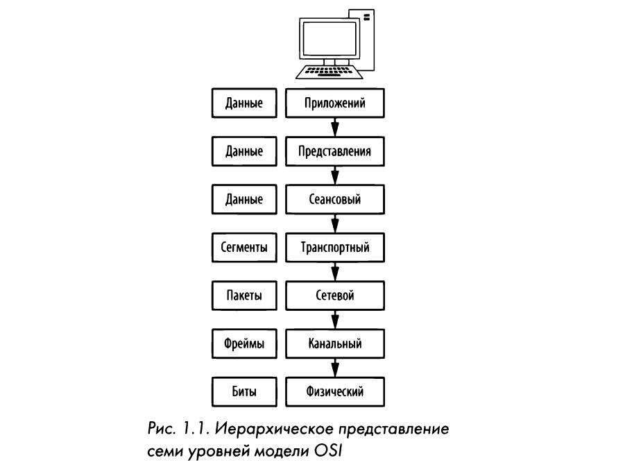
Each layer of the OSI model performs a specific function, as explained below.
Application level (seventh). At this very top level of the 0SI model, a means of user access to network resources is provided. As a rule, it is the only layer available to end users, as it provides the interface on which they carry out all their activities on the network.
Data presentation level (sixth). At this level, the received data is converted into a format that is read by the application level. The order in which data is encoded and decoded at this layer depends on the protocol used at the application layer to transmit and receive data. Multiple forms of data encryption and decryption can also be used at the layer to protect them.
Session level (fifth). At this level, a conversation or communication session takes place between two computers. The session layer is responsible for establishing a duplex (i.e. bidirectional) or half-duplex (i.e. unidirectional) connection, as well as for proper (i.e. not abrupt and sudden) disconnection between two hosts (i.e. network nodes).
Transport level (fourth). The main purpose of the transport layer is to provide reliable transport services to lower layers. Due to the management of data streams, their segmentation and desegmentation, error correction at the transport level ensures error-free delivery of data from one point of the network to another. Ensuring reliable data delivery is extremely difficult, so the 0SI model has a separate layer for this purpose. Both connection-based and connectionless protocols are used at the transport layer. It is at this level that certain firewalls and intermediate, so-called proxy servers work.
Network layer (third). One of the most complex layers of the OSI model, which ensures the routing of data between physical networks and the correct addressing of network nodes (for example, at the 1P address). At this level, data streams are also broken down into smaller parts, and sometimes errors are detected. It is at this level that the participants of the march operate.
Data channel layer (second). This layer provides the means to migrate data over the physical network. The primary purpose of this layer is to provide an addressing scheme for specifying physical devices (eg, MAC addresses). It is at this level that such physical devices as bridges and switches work.
Physical level (first). This is the lowest level of the OSI model, where the medium over which network data is transmitted resides. This level defines the physical and electrical characteristics of all network equipment, including network voltage levels, hubs, network adapters, repeaters, and cables. At the physical level, network connections are established and broken, means of sharing network resources and converting signals from digital to analog and vice versa are provided.
NOTE: For the convenience of remembering the levels of the 0SI model in English, the mnemonic phrase “Please Do Not Throw Sausage Pizza Away” is used, where the names of each level of this model are indicated in capital letters of individual words, starting with the first.
Table 1.1 lists some of the most common protocols used at each level of the OSI model.
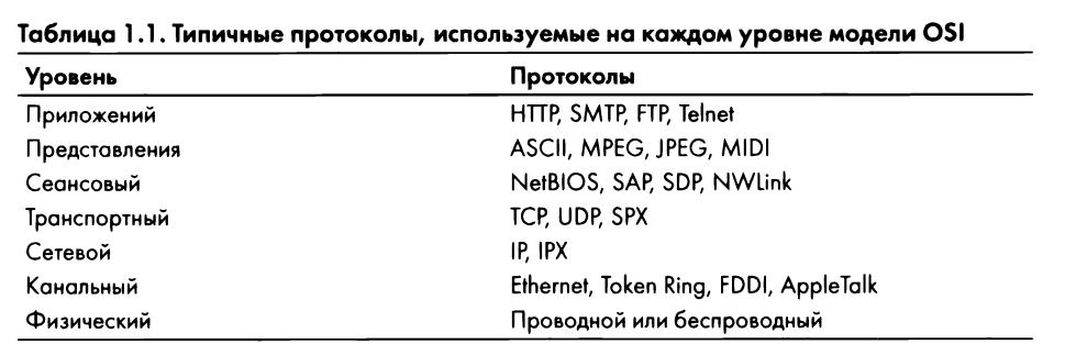
Although the OSI model is only a recommended standard, it should be known by heart because it provides a handy glossary of terms for understanding and describing the difficulties encountered in networks. As you read the book, you will find that routing problems fall into the third level of the model, and programming problems fall into the seventh.
First, data transmission over a network begins at the application layer of the transmission system. Data travels from top to bottom through all layers of the 0SI model until it reaches the physical layer, which is the point from which data is sent from the transmitting system to the receiving system. And the receiving system receives data at its physical layer, from where the data passes from the bottom up through all the layers of the OSI model, ultimately reaching the application layer.
Each layer of the OSI model can only interact with the layers immediately above and below it. For example, at layer 2, data can only be sent to and received from layers and S.
None of the services provided by different protocols at any given layer of the OSI model should be redundant. Therefore, if a protocol provides a particular service at one layer, no other protocol at any other layer must provide the same service. Protocols of different layers may have means that serve similar purposes, but their operation will be slightly but still different.
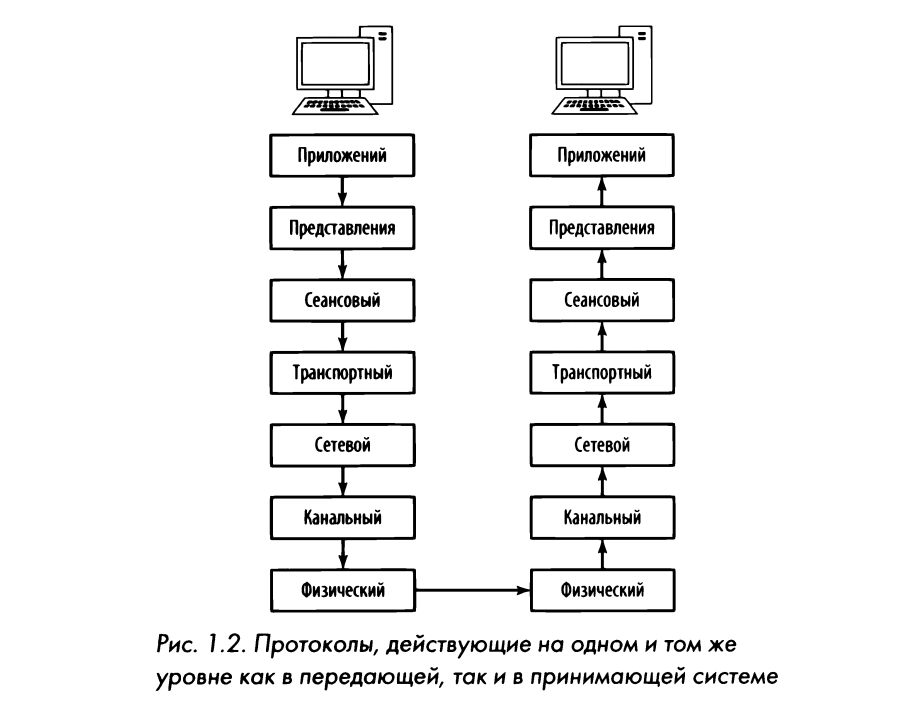
Protocols at the corresponding levels of transmitting and receiving devices complement each other. So, if the protocol at the seventh level of the transmitting device is responsible for formatting the transmitted data, then the corresponding protocol at the seventh level of the receiving device should be responsible for reading the received formatted data.
In fig. Figure 1.2 shows a graphical representation of the 0SI model on two interconnected devices. As you can see, data transmission is top-down on one device, and reception is in reverse on the other device.
Protocols operating at different layers of the OSI model communicate using data encapsulation. Each layer of this model is responsible for adding to the beginning and end of the transmitted data the corresponding header and end switch in the form of additional bits of information intended for interaction between layers. For example, when data arrives at the transport layer from the session layer, the transport layer adds its own header containing the necessary information to the data before passing it on to the network layer.
In the process of encapsulation, a block of protocol data is created, which includes the transmitted data and all added header and end information. As data moves from top to bottom of the OSI model and header and tail information is added to it at different levels, the PDU changes, gradually growing. In its final form, a remote control is formed when it reaches the physical layer, where it is sent to a receiving device at its destination. And on the receiver, the headers and end switches are extracted by the appropriate protocols from the PDU in reverse order as the data passes from the bottom up through the layers of the OSI model. And once the PDU reaches the upper layer of the OSI model, only the data from the original application layer remains.
To demonstrate how data encapsulation works, let’s look at a simplified practical example of creating, transmitting, and receiving a packet in relation to the OSI model. However, packet sniffers rarely mention the session or presentation layer of the OSI model. That is why both of these levels are absent in the example considered here, as well as in other examples of this book.
In this case, an attempt is made to view a web page at http: //www.google.com/. The first step is to create a request packet that is sent from the source client computer to the destination server computer. In this case, it is assumed that a TCP/IP session is already established.
The data encapsulation process in the example considered here is clearly shown in fig. 1.3
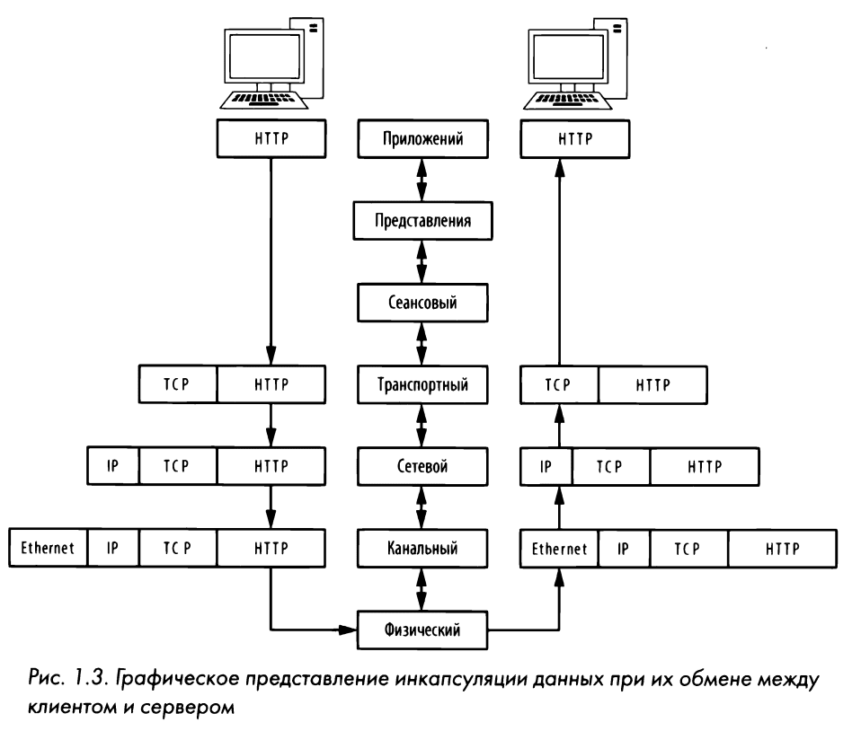
So, let’s start with the Julient computer at the application level. This is about viewing a website page, so the HTTP network protocol is used. Using this protocol, a command to load an index file is issued. htm1 from the page at the above address.
NOTE: In practice, the browser will first ask the website for the root Docs directory, marked with a slash (1). As soon as the server receives this request, it redirects the browser to a file that is configured to serve requests to issue the document root directory. This is usually a file of type index. hbnl or .php index. This will be discussed in more detail in Chapter 9, “Distribution of Upper Layer Protocols” when discussing the NDP network protocol.
As soon as the command is sent from the application layer protocol, all that remains is to deliver the packet to its destination. Data from the packet is transmitted from top to bottom at the transport layer. The HTTP protocol of the application layer uses the TCP protocol, since the first is located in the protocol stack above the second, and actually “sits” on it. At the transport layer, a TCP header is generated, which is added to the PDU block, as shown in Fig. 1.3. This TCP header includes serial numbers and other data that is added to the package and ensures its correct delivery.
NOTE: It is not uncommon for network experts to say that one network protocol is “CIDit” or “EZDit” on another protocol due to the top-down nature of the 0SI model architecture. Thus, the application layer HHTP provides certain services by relying on the dm transport layer TCP to reliably provide its services. And the services of both of these protocols rely on the IP network layer protocol to deliver data to an address. Thus, the HTTP protocol “sits” on the TCP channel, and the latter – on the IP protocol.
After completing its task, the TCP protocol passes the packet to the third layer IP protocol, which is responsible for the logical addressing of the packet. To do this, the IP protocol generates logical addressing information that is added to the PDU, after which the packet is transferred to the Ethernet protocol at the link layer, where the physical Ethcrnet addresses are stored. Thus, the fully assembled packet is transferred to the physical layer, where it is transmitted in binary form of ones and zeros over the network
The complete packet is carried over the network’s cable system, eventually reaching Google’s web server. This web server starts reading the received packet from the bottom up, that is, starting with the transport layer information, which contains information about the physical addressing of the Ethernet protocol. This information is used by the network adapter to determine whether a received packet is intended for that particular web server. After processing this information, the second-level information is removed from the packet and the third-level information is processed.
Layer 3 IP addressing information is read to ensure that the packet is correctly addressed and not fragmented. This information is also removed from the packaging to allow for next-level information processing.
Next, information is read from the fourth layer of the TCP protocol to ensure that the packet arrived in the correct sequence. The fourth-layer information is then removed from the packet, leaving only the application-level data that can be passed to the backend application deployed on the specified web server. In response to this packet from the client, the server must first transmit an acknowledgment packet over TCP to inform the client that its request was successfully received, and then we request the index. html.
All packets are created and processed in the manner described in this example, regardless of the protocols used. But at the same time, not every packet in the network is formed starting from the application layer protocol. Often in the network you can find packets that contain information only from the second, third or fourth level protocols.
Now let’s look at the network hardware where all the hard work of exchanging data over the network is done. In this section, we will talk about the most characteristic components of network equipment, which include hubs, switches and routers.
Concentrators
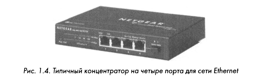
A typical hub is a rectangular case with a range of RJ-45 ports, similar to the NETGEAR model shown in Fig. 1.4 Hubs range from very small 4-port devices to large 48-port rackmount devices for enterprise environments.
Hubs can generate a lot of unnecessary network traffic and work only in half-duplex mode, that is, they are not able to simultaneously transmit and receive data. Therefore, hubs are generally not used in most modern networks, as well as in high-traffic networks, where switches, discussed below, are used instead. However, you should know how hubs work because they play an important role in a packet sniffing technique called “hub packet sniffing” discussed in Chapter 2, “Connecting to a Hub”
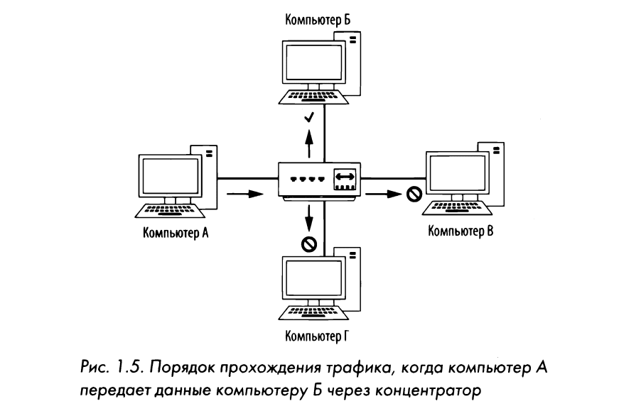
A hub is just a repeater that works at the physical layer of the OSI model. It accepts packets sent from one port and forwards them to all other ports, that is, it repeats them, and the duty of the receiving device is to accept or reject each packet. For example, if you want to transfer data from a computer connected to port 1 of a 4-port hub to a computer connected to port 2, the hub will direct these packets to ports 2, W, and 4. Clients connected to ports Z and 4 , will check the recipient address field for compliance with the Media Access Control standard, or simply the MAC addresses in the packet and find that the packet is not intended for them, and therefore skip (i.e. reject) it. In Fig. Figure 1.5 shows an example of computer L sending data to computer B. When computer A sends this data, all computers connected to the hub receive it. But only computer B actually accepts the sent data, while the other computers reject it.
As an analogy, let’s say that the message “Attention to all employees in the marketing department” is sent by e-mail to everyone in the company, and not just to those who work in the marketing department. After seeing this message, employees in this department will open it, and other employees in the company will ignore it, since it does not concern them. This example clearly shows that this approach to data transmission over the network leads to the appearance of unnecessary traffic and wasted time. But that’s how the hub works. The optimal option for replacing hubs in production and high-throughput networks are switches – duplex devices capable of synchronously transmitting and receiving data.
Switches
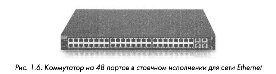
Like a hub, a commuter device is designed to repeat packets. But unlike a hub, a switch does not send data to every port, but only to the computer for which it is intended. Switches are very similar to hubs, as shown in Fig. 1.6.
Some major switches (such as Cisco) run specialized software or web interfaces developed by OEMs. Such switches are commonly referred to as managed switches and provide a number of useful network management capabilities, including enabling and disabling ports, viewing port statistics, making configuration adjustments, and remotely rebooting.
Passengers provide additional functionality for processing transmitted packets. To communicate directly with certain devices, switches must uniquely recognize devices by their MAC addresses. This means that they must operate at the data link layer of the OSI model.
Switches store the addresses of the second level of each device connected to them in the table of associative memory (CAM – Content Addressable Memory), which acts as a regulator. When a packet is transmitted, the switch reads information from the second layer header in that packet and, using the associative memory table as a reference, determines which ports the packet should be directed to. Switches send packets only to certain ports, thereby significantly reducing network traffic.
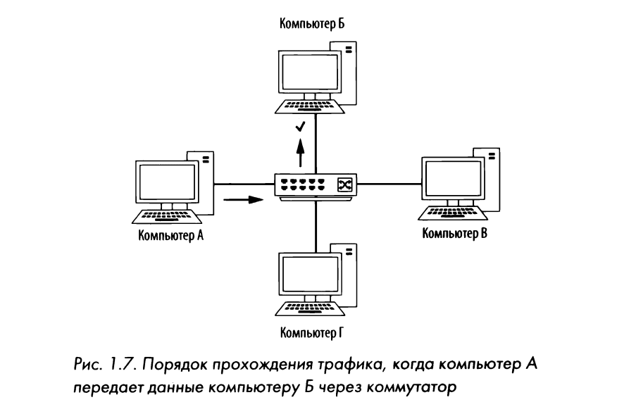
In fig. Figure 1.7 shows the flow of network traffic through a switch. In particular, computer A sends data only to computer B as its intended recipient. At the same time, there can be many conversations on the network, but the data is transmitted directly between the suburban and the designated receiver, and not between the switch and all the computers connected to it.
Routers
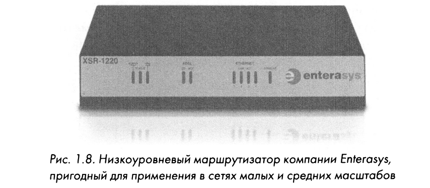
RoutingisATF is an advanced network device with a much higher level of performance than a switch or hub. A router can take many shapes and forms, but usually has a few LEDs on the front and a number of network ports on the back, depending on the size of the network. An example of a small marshugizer is shown in Fig. 1.8.
Routers operate at the third layer of the OSI model, where they are responsible for forwarding packets between two or more networks. The process by which routers direct network traffic between networks is called routing. There are several types of routing protocols that determine the order in which different types of packets are routed to other networks. Typically, routers use third-level addresses (such as 1P addresses) to uniquely identify devices on the network.
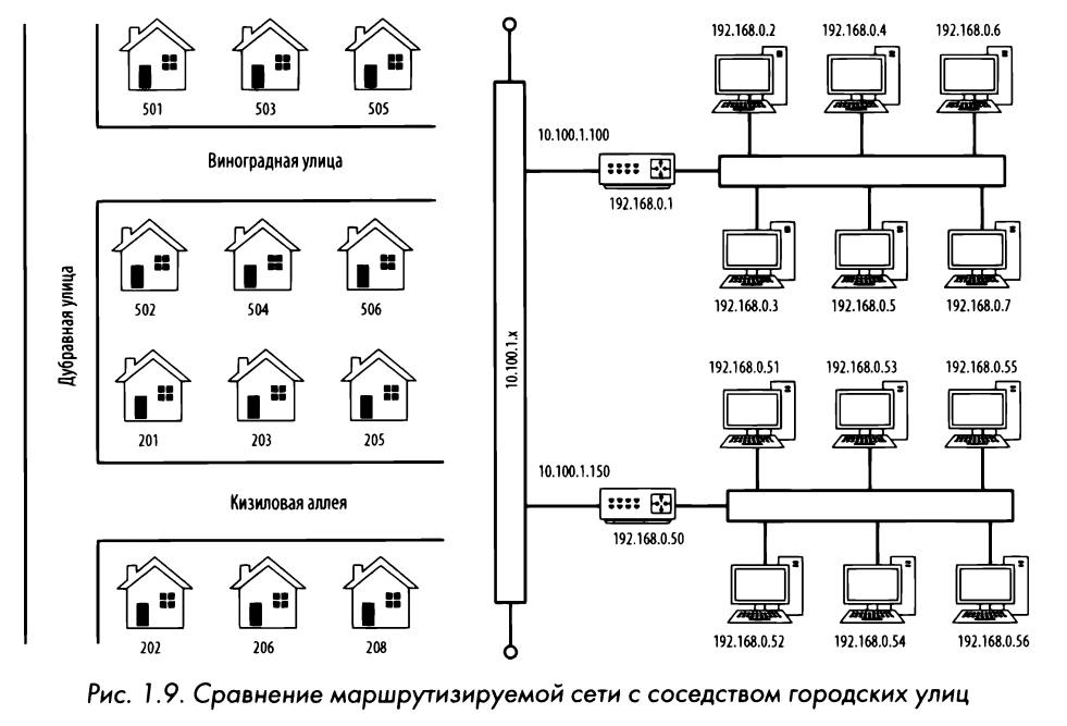
To illustrate the concept of routing, let’s turn to the analogy of a neighborhood of city streets, representing houses with their addresses in the form of computers, and each street as a network segment (Fig. 1.9). When leaving the house, you can easily visit neighbors in other houses on the same street by walking straight down the sidewalk from the front door of one house to another. Similarly, a switch provides communication between all computers in the same network segment.
But communication with neighbors living on another street is similar to communication with a computer on another segment of the network. Looking at fig. 1.9, let’s assume that you live at Vynogradna Street, building 502, and you need to get to the house at Kyzyl 206. To do this, you need to turn first to Dubravna Street, and then to Kyzylova Alley. This can be compared to the intersection of different network segments. Yes, if the device is located at 192.168. 0. H, you need to contact the device located at 192 .168. 0. 54, he has to do it first through his marchugiser to reach the net at 10 .100 . 1. x and then through the router of the destination network segment before reaching that segment.
The size and number of routers in a network usually depends on its size and function. Only one small router can be installed on the border of personal, home and small office networks. And in large corporate networks, you may need several routers installed in different departments of the organization and connected to a single central router or a third-level commuter link (that is, an advanced type of commuter transport with built-in capabilities to function as a router).
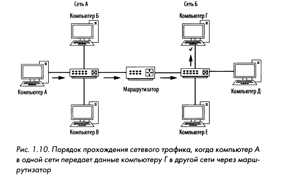
By looking at the following network diagrams, you will eventually understand how data passes through different points on the network. So, in fig. Figure 1.10 shows a very common form of descending network layout. In this case, two separate networks are connected through one router. If a computer on network A needs to communicate with a computer on network B, then the data transmitted from it must pass through the router.
Network traffic can be classified into three types: broadcast, multicast, and unicast. Each of these classifications of network traffic has its own characteristics that determine the order of packet processing in network equipment.
Broadcast traffic
A broadcast packet is a packet that is sent to all ports on a network segment, regardless of whether the port is on a hub or a switch. There are forms of second and third level traffic broadcasting. At the second layer, the MAC address ff: is a reserved broadcast address, and any traffic directed to this address is propagated throughout the network segment. There is also a broadcast address on the third layer, but it varies depending on the network address range used.
The largest of all 1P addresses allowed in the IRnet address range is reserved for use as a broadcast address. Yes, if the computer has an address of 192.168. 0 .20 and the subnet mask 255 .255.255.0, the address 192.168.0.255 turns out to be a broadcast (more about 1P addressing will be discussed in Chapter 7, “Network Layer Protocols”).
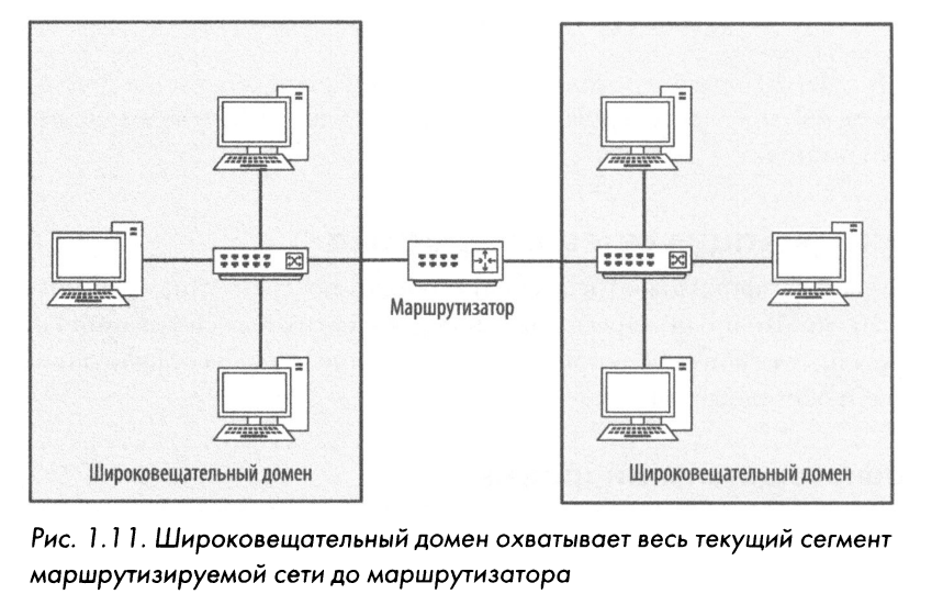
The boundary to which broadcast packets can spread is called a broadcast domain, which is a network segment where any computer can directly transmit data to another computer without the help of a router. In large networks with many hubs or switches connected via different communication media and media, broadcast packets from one switch reach all ports on all other switches in the network because packets are repeated as they travel from one switch to another. In fig. Figure 1.11 shows an example of two broadcast domains in a small network. Each broadcast domain is extended until it reaches the router, and therefore broadcast packets circulate only in that particular domain.
The previously mentioned analogy with the neighborhood of city streets also makes it possible to clearly show the principle of operation of broadcast domains. In particular, the broadcast domain can be thought of as a neighborhood street where all the neighbors are sitting on their porch. If you stand on your porch and yell, the people on your street will be able to hear you. But if you want to talk to someone on the other street, you’ll have to find some way to do it directly instead of broadcasting (shouting) from your front porch.
Multicast is the simultaneous transmission of a packet from one source to many destinations. The goal of multicast transmission is to use as little network bandwidth as possible. Optimizing multicast traffic is to duplicate the data flow less along its route to its destination. The specific handling of multicast traffic depends on its implementation in individual network protocols.
Multicast traffic is implemented primarily through an addressing scheme that adds packet receivers to a multicast group. This is how IP Internet multicasting works. This addressing scheme ensures that packets are not forwarded to computers for which they are not intended. If you find a 1P address in the range 224.0.0.0 to 239 .255 .255 .255, then it is most likely being processed for multicast traffic, as addresses within these ranges are reserved for such purposes.
A unicast packet is transmitted directly from one computer to another. The specific operation of unicast transmission depends on the network protocol used. An example is a device that needs to communicate with a web server. This point-to-point connection, and therefore the data transfer process, must be initiated by the client device, which transmits the packet only to the web server.
This chapter introduced the networking basics you need to know in order to analyze packets. In particular, it is necessary to clearly understand what is happening at this level of data transmission over the network before starting network diagnostics. In Chapter 2, Connecting to a Network, we discuss a number of packet capture methods that need to be analyzed.