The study and analysis of network protocols has always been an important part of work in the field of network security and system administration. Transport-level protocols that ensure reliable data transmission between devices on a network are critical to the proper operation and security of network connections. Wireshark and tcpdump are powerful tools that allow you to analyze and study transport layer protocols in a network. They provide the ability to monitor data exchange between devices, identify problems, detect errors, and improve network performance. This article focuses on an overview of transport layer protocols and how Wireshark and tcpdump can be used to analyze and monitor them. You will learn exactly which protocols are included in this layer, how they work, and why they are important for the functioning of the network.
It will also describe how Wireshark and tcpdump can help network security professionals and administrators monitor and analyze these protocols to ensure network security and performance. Understanding transport layer protocols and being able to use Wireshark and tcpdump to analyze them are essential skills for anyone working in network security and administration. This text will help you learn the basics of these skills and put them into practice to ensure network reliability and security. In this section, we will continue to consider individual protocols and their manifestation at the packet level. Moving up the OSI model, we will look at the transport layer and the most commonly used protocols at this layer, TCP and UDP.
The ultimate goal of the Transmission Control Protocol (TCP) is to ensure the reliable delivery of data from one endpoint on a network to another. As defined in RFC 793, the TCP protocol is responsible for tracking data sequences and error correction, and ultimately ensuring that data is delivered to its destination. TCP is considered connection-oriented because it establishes a formal connection before transferring data, controls the delivery of packets, and generally attempts to formally close communication channels at the end of a transfer. Many of the most common application layer protocols use TCP and IP to deliver packets to a receiver.
The TCP protocol provides a variety of functionality, which is reflected in the complexity of its header. As shown in fig. 8.1, the packet header of this protocol consists of the following fields.
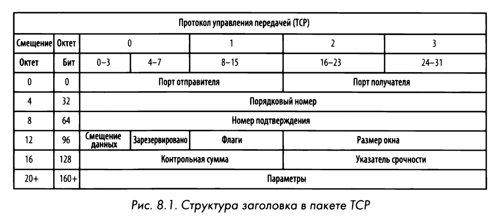
Output port. The port used to transmit the packet on the sender’s machine.
Port of destination. The port to which the packet is forwarded on the recipient machine.
Sequence number. A number used to identify a TCP segment. The value set in this field ensures that no part of the data stream is lost during transmission.
Confirmation number. The sequence number expected to be received in the next packet from another device participating in the network communication.
Flags. This field sets the URG, ACk, PSH, RST, SYN, and FIN flags to determine the type of TCP packet being transmitted.
Window size. The size of the TCP packet receive buffer, specified in bytes.
Checksum. It is used to ensure that the TCP header and data remain unchanged as they arrive at the receiver.
Urgent Pointer. If the URG flag is set, the contents of this field are checked for additional instructions as to where the CPU should begin reading data in the packet.
Options (0options). This field contains additional parameters that can be specified in the TCP packet.
Файл перехоплення: tcp _JЮrts . pcapng
All TCP communication takes place tcp_ports between the source and receiver ports, the numbers of which can be found in each TCP header. The port can be compared to a jack on an old telephone patch panel (switch). The operator of the telephone exchange (or telephone operator) constantly monitored the indicators and plug connectors on this panel. And as soon as the call indicator light came on, the operator contacted the subscriber, asked who he wanted to talk to, and then connected him to another subscriber by inserting a cable with a plug into the corresponding socket of the switch. To establish a communication session, it was necessary to have a sender port (that is, a subscriber) and a receiver port (that is, a receiving subscriber). TCP ports work in a similar way.
To transfer data to a specific application running on a remote server or device, a TCP packet must specify a known port number of the remote service where the packet can be received. If you try to access the application on the remote machine through another port on which it is not configured, the data exchange will not take place.
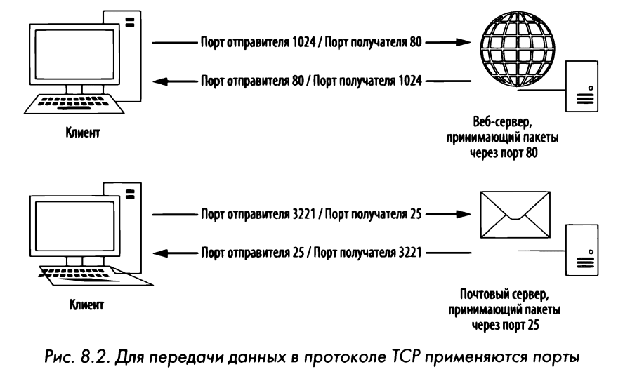
The sender port in this sequence is not so important and can be chosen arbitrarily. The remote server will determine the port number with which communication will be carried out from the outgoing packet sent to it (Figure 8.2).
There are 65535 ports for TCP communication. All of them, as a rule, are divided into the following categories.
A group of well-known ports, otherwise known as standard (or permanent) ports, numbered from 1 to 1023, where the number 0 is reserved and therefore ignored. Well-known and well-established services usually use ports that belong to the system port group.
A group of ephemeral ports. This is a group of ports numbered between 1024 and 65535, although these limits may be defined differently in some operating systems. Only one service can communicate through a port of this category at a time, and therefore, in modern operating systems, sender ports are chosen randomly to distinguish one session from another. Typically, sender ports are from an available range of temporary (ie, dynamically assigned) port numbers.
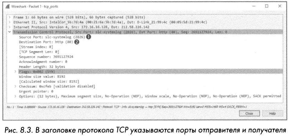
As an example, consider a pair of TCP packets from a tcp port capture file. RSARPD to identify the port numbers used in them. This file contains N TT P network traffic captured when a client browses two websites. As mentioned earlier, the HTTP protocol uses the TCP protocol to exchange data, which is a typical example of TCP traffic.
The first two values in the header of the first packet from this file (Fig. 8.3) indicate the port of the sender and recipient of this packet. Specifically, this packet is sent from a host located at 172.16.16.128 to a host located at 212.58.226.142. The sender port is 2826, which means it is a temporary port. (Recall that the sender’s ports are randomly selected by the operating system, although their random numbers are usually incremented.) And the receiver’s port is numbered 80, which is the standard system port assigned to web servers running HTTP.
Note that in Wireshark the ports mentioned above are labeled slc-systalog (2826) and http (80). The Wireshark application keeps a list of ports and where they are most frequently used. Although system ports are generally designated as the most frequently used, many ephemeral ports are associated with frequently used services. Such marking of ports with special labels can be misleading, and therefore it is generally better to redefine it by disabling name resolution at the transport level. To do this, in the main menu, select the Edit4Preferences4Name Resolution command and uncheck the Resolve Transport Names checkbox). If you want to leave this check box, but want to change the order of a specific port in Wireshark, you will need to make the appropriate changes to the services file located in the Wireshark system directory. The contents of this file are based on a list of common ports (see “Using the custom hosts file” in Chapter 5, “Advanced Wireshark Features” for an example of editing the file to resolve names).
The second packet is sent in the reverse direction from the host located at 212.58.226.142 to the host located at 172.16.16. 128 (Fig. 8.4). Like IP addresses, the sender and receiver ports are now reversed.
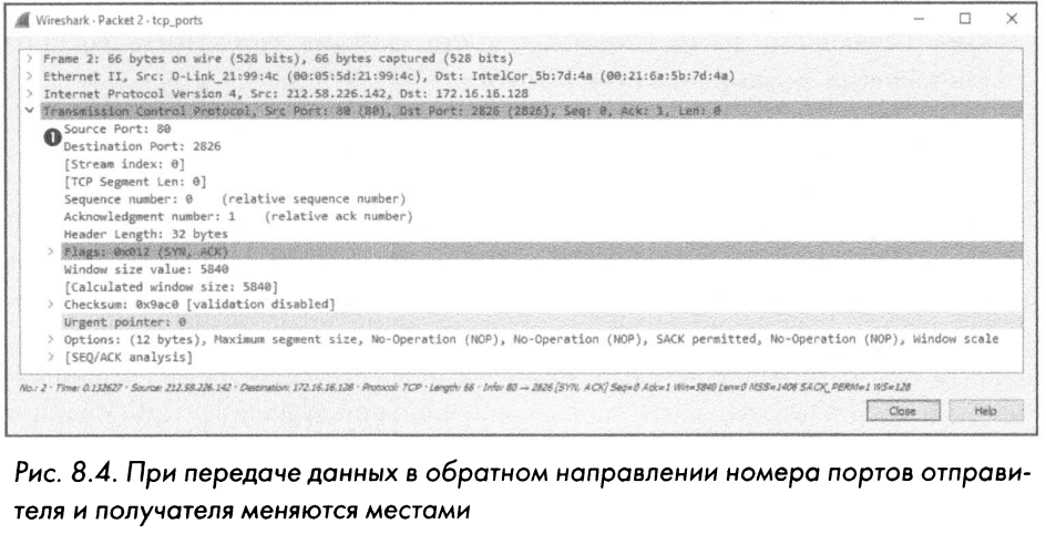
As a rule, data exchange using the TCP protocol occurs as follows: the sender’s port number is arbitrarily chosen to transmit data to the recipient via a known port. And once the initial packet is sent, the remote receiving device will communicate with the transmitting device through the established ports.
The intercept file from the example discussed here contains another communication stream. Try to determine the port numbers selected in this case for communication.
Handshake file: tcp _handshake.pcapng
All TCP connections must be initiated by the TCP protocol. RSARPD is concerned with establishing communication between two hosts. Such a process serves several purposes, including the following:
The transmitting host can check if the receiving host is ready to communicate.
The transmitting host can check whether the receiving host is ready to receive data on the port through which the transmitting host is trying to communicate.
The transmitting host can send its initial sequence number to the receiving host so that both hosts can maintain a given order of packets in the flow.
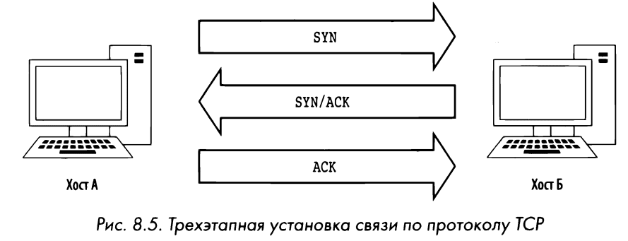
The process of establishing communication using the TCP protocol takes place in three stages, as shown in Fig. 8.5. At the first stage, the device to which the data needs to be transferred (host A) sends a TCP packet to the recipient (host B). This initial packet contains nothing but lower-level protocol packet headers. The TCP header of this packet contains the SYN flag, as well as the starting sequence number and the maximum segment size (MSS) used in subsequent data exchanges. Host B responds to this packet by sending a similar packet with the SYN and ASK flags set and its original sequence number. And finally, host A sends another, final packet to host B with the ASCA flag set. Once this process is complete, both hosts should have all the information they need to communicate properly.
To see the process described here in action, open the .rsarpd tcp handshake intercept file. To simplify packet analysis, Wireshark has a mode for replacing serial numbers of TCP packets with relative numbers. However, for the purposes of this example, it is better to disable this mode in order to keep the packet sequence numbers. To do this, select the Edit4Preferences command from the main menu, expand the Protocols heading, select the TCP option, uncheck the box “Relative sequence numbers” in the window that opens, and click OK.
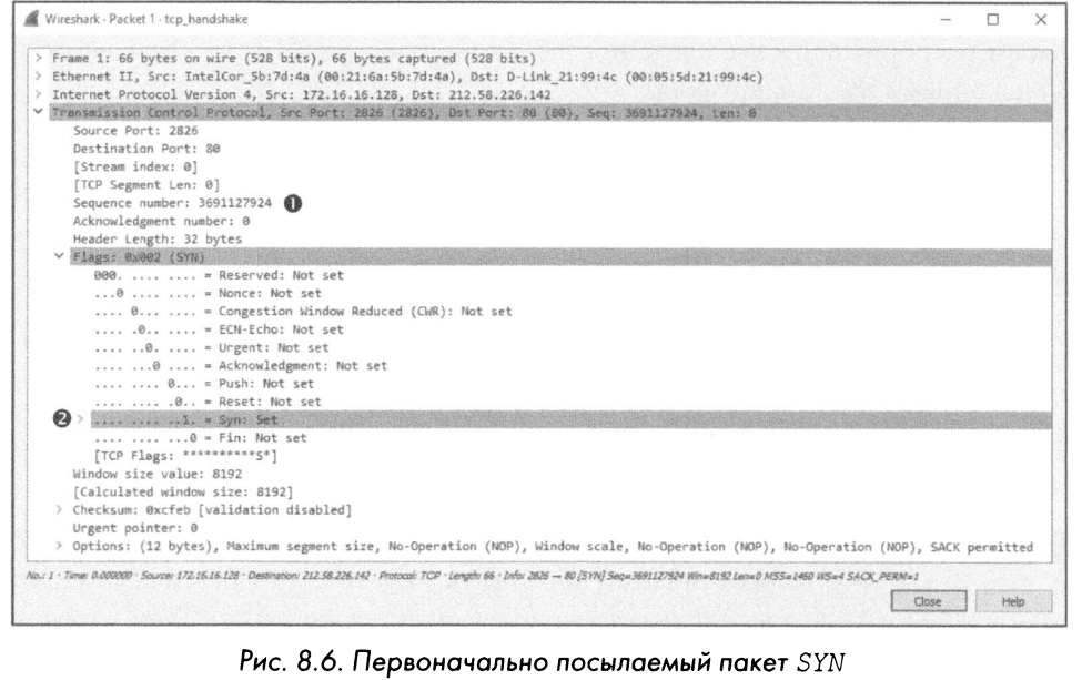
The first packet in this intercepted traffic is the originally sent SYN packet (Figure 8.6). This packet is transmitted from the host located at 172.16.16.128 on port 2826 to the host that receives the transmitted packet at address 212.58.226.142 on port 80. As you can see, this packet transmits the serial number 3691127924.
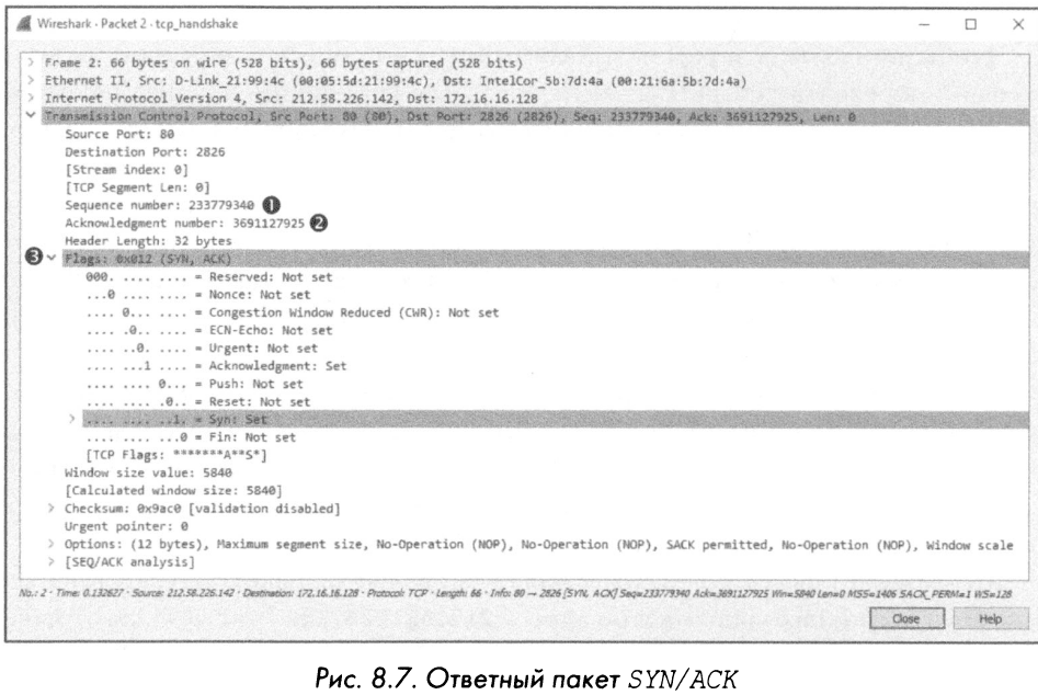
The second in the handshake process is a SYN/ASK packet with a response from the host located at the address 212.58.226.142 (Fig. 8.7). This tayuke package contains the initial serial number (233779340) of this host and the confirmation number (3691127925). The acknowledgment number shown here is one more than the sequence number from the previous packet because this field indicates the next sequence number the host expects to receive.
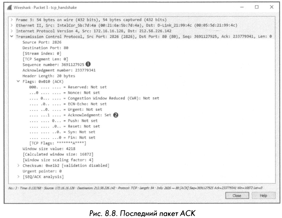
And the last in the process of the three-stage communication setup according to the protocol is the ASK packet sent from the Host located at the address 172.16.16.128 (Fig. 8.8). As expected, this packet contains the serial number 36911- 27-925, which is determined based on the confirmation number in the corresponding field of the previous package.
Communication is established before each sequence of data exchange using the TCP protocol. If you sort through a large intercept file in search of the beginning of a data exchange sequence, the obvious sign is the sequence of SYN-SYN / ACk-ACk packets.
Capture file:tcp _ teardown.pcapng
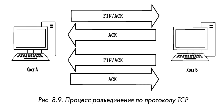
Most greetings ultimately end in goodbyes, and in the TSR protocol, every hookup session ends in a breakup. In particular, breaking the connection with the TSR protocol serves to correctly terminate the communication session established between two devices after they have completed the data exchange. This process involves four packets and the setting of the FIN flag to indicate the end of communication and disconnection. In the disconnection sequence, host A reports the end of data exchange by sending a TSR packet with the FIN and ASK flags set. Host B responds to this with an ACK packet and transmits its FIN/ACK packet. In turn, 217 host A responds with an ASK packet, : ~ completing the data exchange. This process is clearly shown in fig. 8.9.
Observe the process. Starting with the first packet in the intercepted sequence (Figure 8.10), we can see that the device located at 67 .228 .110 .120 initiates the shutdown by sending a packet with the FIN and ASK flags set.
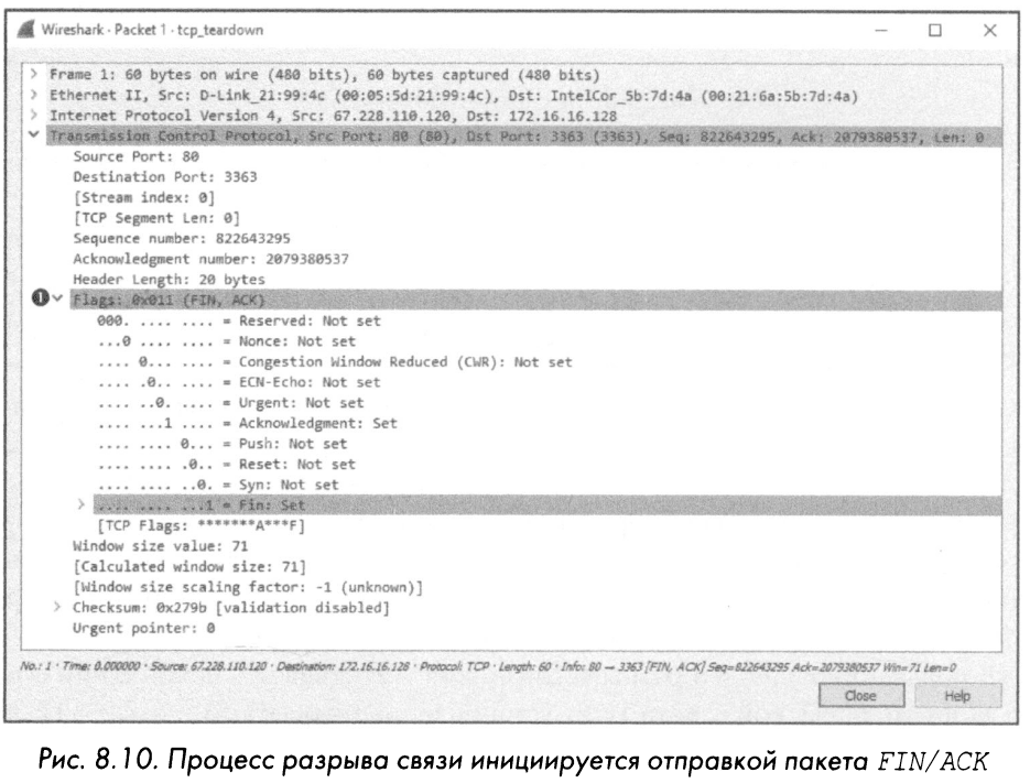
Once the first packet is sent, the host located at 172 .16.16.128 will respond with an ASK packet to acknowledge receipt of that packet and then send its FIN/ACk packet. The shutdown process will end when the host located at 67 .228 .110 .120 sends the final packet to the ASC. This will end the data exchange between the two devices. If they need to reconnect, they will have to perform the three-step TCP connection again.
Interception file: tcp _ refuseconnection. pcapnq
Ideally, every connection should drop the connection. rsarpd correctly terminates by starting the TCP disconnection procedure. However, in the real world very often connections are suddenly broken. For example, the host could be misconfigured, or a potential attacker could run a port scanning program. In such cases, if the device does not want to accept the packet sent to it, it can send a TCP packet with the RST flag set. This flag is used to indicate that the connection has been dropped suddenly or that the connection attempt has been rejected.
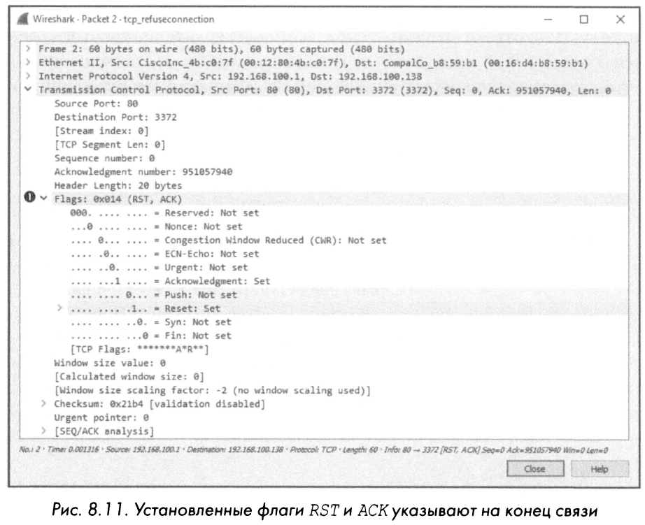
The tcp refuseconnection .rsarpd intercept file shows an example of network traffic that includes an RST packet. The first packet in this file is sent by the host located at 192 .168 .100 .138 to try to contact the host located at 192 .168 .100 . 1, via port 80. What this host doesn’t know is that the host at 192.168.100.1 is not accepting packets on port 80 at all because it is a Cisco router that does not support a web configuration interface. Therefore, there is no service configured to receive connections on this port. In response to such an attempt to establish a connection, the host was located at the address 192.168.100. 1, sends a packet to the host located at the address 192.168.100.138, stating that the connection cannot be established on port 80. In Fig. Figure 8.11 shows how the TCP header of the second packet can defeat this communication attempt. In particular, the RST packet contains nothing more than the RST and ASK flags set in its header, after which no more data is exchanged.
In any case, the RST packet terminates the connection, regardless of whether it is the first attempt to establish a connection, as in this example, or is sent as part of a host-to-host connection.
Capture file: udp _dnsrequest.pcapng
The UDP protocol (User Datagrarn Protoc.ol protocol dnsrequest. RSARPD user datagrams) is another fourth-level protocol often used in modern networks. While TCP is designed for reliable data delivery with built-in error checking, UDP’s goal is to provide fast data transfer. It is for this reason that the UDP protocol does not require a prior connection and, accordingly, cannot guarantee the delivery of packets when transmitting data. UDP does not formally establish and terminate connections between hosts, as TCP does.
Network traffic using the connectionless UDP protocol, which does not provide reliable data services, can appear unpredictable, to say the least. And that’s right! As a result, other protocols that use UDP as a transport protocol usually have built-in support for reliable data transfer or use specific protocol features
ICMP to improve connection reliability. For example, the application layer protocols DNS and DHCP, which rely heavily on network packet rates, use UDP as the transport layer protocol, but they also provide error checking and retransmission timers.
The UPD header is much smaller and simpler than the smart TCP headerdnsrequest.pcapng. As shown in Fig. 8.12, it consists of the following fields.
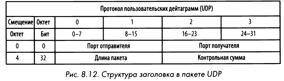
Output port. The port used to transmit the packet on the sender’s machine.
Port of destination. The port to which the packet is forwarded on the recipient machine.
Package length. Packet length in bytes.
Checksum To guarantee the integrity of the data when it arrives at the destination.
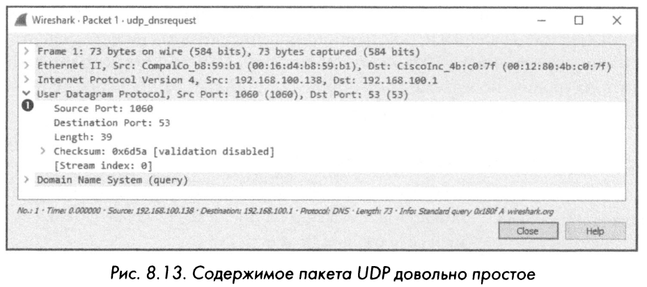
The .rsarpd udp dnsrequest intercept file contains one packet. This package is DNS-3anpoc, which uses the UDP protocol. If you expand it, you can find four fields here, as shown in fig. 8.13. It is very important to remember that UDP does not ensure reliable delivery of packets. Therefore, any application using this protocol must take additional measures to ensure reliable packet delivery, if necessary. This is not at all like the TCP protocol, where the connection is formally established and broken, and there are built-in tools to verify the successful result of the packet transfer.
This chapter introduced the TCP and UDP transport layer protocols. Unlike network-layer protocols, TCP and UDP form the basis of much of everyday network communication, and therefore the ability to analyze them effectively plays a critical role in developing a competent packet analyst.
We used materials from the book “PRACTICAL RACKET ANALYSIS” written by Chris Sanders.