When connecting to a local network, it is extremely important to ensure its stability and security. Wireshark and tcpdump are two powerful tools that help analyze and monitor network traffic, ensuring the reliability and security of your local network. In this SEO text, we will look at the important aspects of connecting to local networks and using Wireshark and tcpdump to ensure their reliability and security. You’ll learn how these tools can help you detect anomalies in network traffic, identify potential security threats, and improve your network’s performance. Our article will give you a deep understanding of the role of Wireshark and tcpdump in LAN connectivity and help you use them to ensure an efficient and secure environment.

Don’t let network issues hinder your productivity – trust Wireshark and tcpdump for the best results. Ensuring a stable and secure connection to local networks is becoming an increasingly important task in today’s digital world. Frequent network outages or security threats can lead to serious problems, including loss of data or access to critical resources. Wireshark and tcpdump have become indispensable tools for professionals in the field of network security and network administration. In this part, we will take an in-depth look at the capabilities of Wireshark and tcpdump and their role in ensuring the reliability of local networks. We’ll reveal how these tools allow you to analyze network traffic, detect anomalies, identify potential threats, and take the necessary actions to improve network performance. Our article will also provide useful tips on how to optimally use Wireshark and tcpdump, as well as important practical tips for network security. You will learn how to identify and respond to potential threats that may appear on your local network. With the help of Wireshark and tcpdump, you will be able to maintain a reliable and secure network that contributes to the efficient operation of your organization or home. Don’t let network problems get in the way of your success – trust Wireshark and tcpdump to ensure the best performance and security of your network.
The key to effective packet sniffing is to physically position the packet sniffer to collect data properly. It is not uncommon for packet sniffers to refer to the location of the packet sniffer as a network listening or network connection.
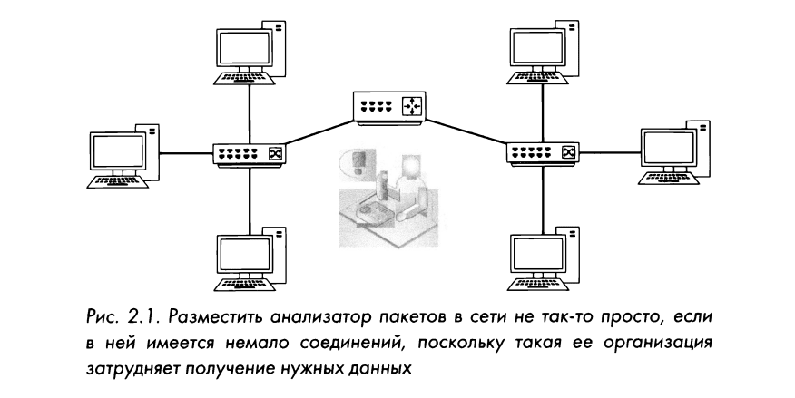
Unfortunately, packet sniffing is not enough to connect a laptop to a network port and intercept traffic. In fact, sometimes it is much more difficult to place a packet sniffer on the network than to actually analyze the packets. Deploying a packet sniffer is not easy because devices can be connected to the network using a wide variety of network equipment. A typical situation for packet sniffing is shown in Fig. 2.1. Each of the devices in a modern network (connectors and routers) processes network traffic differently, so it is necessary to take into account the physical organization of the analyzed network.
The purpose of this chapter is to help you better understand packet sniffing in networks with a wide variety of topologies. But first, let’s look at how we can see all packets passing through the network we connect to for packet analysis.
Before analyzing packets on the network, you must have a network interface card (NIC), also known as a network adapter, that supports a promiscuous mode driver for listening on the network. In mixed mode, the network adapter can view all packets passing through the network.
As explained in Chapter 1, Packet Sniffing and Networking Basics, devices commonly receive packets from broadcast network traffic that are not actually intended for them. For example, the Address Resolution Protocol (ARP) is an extremely important tool in any researched network to determine the MAC addresses corresponding to a specific 1P address. To find a matching MAC address, a device sends a broadcast packet over the ACP network protocol to every device in its broadcast domain, hoping that the correct device will respond to the packet.
A broadcast domain (that is, a network segment where any computer can transmit data directly to any other computer without the help of a router) can consist of several devices. But only the right receiver in this domain should be interested in receiving a broadcast packet transmitted via the ARP network protocol. And it would be completely inefficient if every device on the network processed a broadcast packet transmitted via the network ARP protocol. Conversely, if the packet is not intended for a device, and therefore not needed, the network adapter of that device will drop the packet instead of passing it to the central processing unit (CPU) for processing.
Dropping packets not intended for the receiving host increases the efficiency of data processing in the network, but this mode of operation of the network adapter is not suitable for packet sniffing. Packet sniffers typically need to intercept every packet sent over the network to ensure they don’t miss any important information.
By using a mixed-mode network adapter, you can ensure that all network traffic is intercepted. When a network adapter is in promiscuous mode, it forwards every packet it detects to the host processor, regardless of the destination address. And as soon as the packet arrives at the CPU for processing, the application that analyzes the packets can take it for analysis.
Mixed mode is supported by most modern network adapters, and Wireshark includes a libpcap/WinPcap driver that allows you to switch a network adapter directly to mixed mode from the Wireshark GUI. (See Section H, “Introduction to Wireshark” for details on the libpcap/WinPcap driver.)
Most operating systems, including Windows, do not allow the use of a network adapter in mixed mode unless there are elevated user rights. Unless you have a legitimate reason to obtain such authority on your system, you most likely will not be able to perform this kind of packet analysis on that particular network.
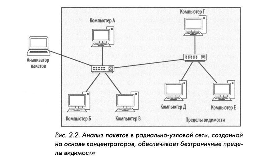
Analysis of packets in a network where hubs are installed is the dream of any packet sniffer. As explained in Chapter 1, “Packet and Network Sniffing Basics,” network traffic that passes through a hub arrives at every port connected to that hub. Therefore, to analyze traffic passing through a computer connected to the hub, it is enough to connect a packet sniffer to an empty hub port. This will allow you to view all communication with this computer, as well as with any other devices connected to the same hub. As shown in fig. 2.2, the limits of visibility are unlimited when connecting a packet sniffer to a hub-based network.
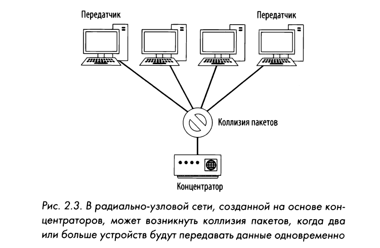
But now, unfortunately, networks are very rarely built on the basis of hubs, as their administration is very difficult. In such networks, only one device can transmit data through the hub at the same time, and therefore all devices connected to it must compete for the right to transmit data with all other devices in the network. If data is transmitted by two or more devices simultaneously, the so-called phenomenon of packet compression occurs, as shown in Fig. 2.3.
As a result, packets can be lost, and to recover from this situation, the transmitting devices will need to retransmit them, which leads to a drop in network bandwidth.
As traffic levels and collisions increase, devices may have to retry packets three or four times, significantly reducing network performance. Thus, it is not difficult to understand why most modern networks of any size use switches. But despite the fact that concentrators are rarely used in modern networks, they are sometimes found in those networks where outdated equipment or specialized devices are supported, for example, in networks of automated process control systems (ACS TP).
The easiest way to find out if you have a hub on your network is to look in your server room or network wiring closet, where most hubs have a special label. If that doesn’t help, look in the darkest corner of the server room, where network equipment is usually covered in a thick layer of dust.
Switches are most often used as connecting devices in modern networks. They provide an efficient order of data transmission for broadcast, multicast and unicast traffic. Switches allow full-duplex data transmission, which means that machines can transmit and receive data at the same time.
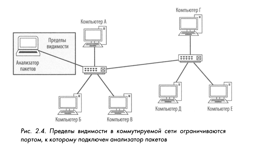
Unfortunately, switches make it difficult for packet explorers. By connecting your packet sniffer to a switch port, you can view only a portion of the broadcast traffic, as well as the traffic sent and received by the device on which the packet sniffer is installed (Figure 2.4). In order to intercept traffic from a target device on a dial-up network, additional steps will have to be taken. There are four ways to intercept such traffic: port mirroring, hub packet sniffing, using a network tap, and infecting the ARP cache.
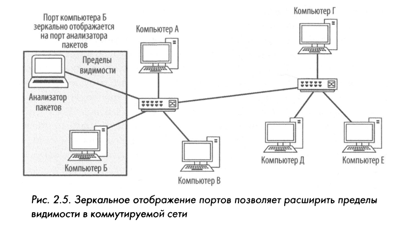
Port mirroring, otherwise known as port panning (ran sPanning), is considered perhaps the easiest way to intercept network traffic from a target device on a switched network. To do this, you need to have access to the command line or web management interface of the switch to which the target computer is connected. Additionally, the passenger must support port mirroring and have an empty port to which the packet sniffer can be attached.
To enable port mirroring, issue a command that causes the switch to copy all traffic from one port to another. For example, to intercept all traffic transmitted and received by a device connected to port Z of the switch, connect a packet sniffer to its port 4, and a mirror port Z to port 4. The process of mirroring packets is clearly shown in Fig. 2.5.
The order of port mirroring depends on the specific model of the switch. For most industrial switches, you will have to register through the command line interface and configure port mirroring with a special command.
When mirroring ports, their bandwidth should be taken into account. Some switch manufacturers allow multiple ports to be mirrored to a single port, and this feature can be useful when analyzing traffic between two or more devices on the same switch. Let’s consider, however, what can come out of this case by making simple mathematical calculations. If, for example, there is a 24-port switch where 23 ports are mirrored onto a single port for duplex data transmission at 100 Mbps, then the data must flow through that port at 4600 Mbps. if network traffic reaches a certain level. Sometimes this situation is called oversubscription. In such cases, switches are known to drop unnecessary packets or completely disrupt internal electrical circuits, completely preventing data transmission. Therefore, make sure that by intercepting packets in the manner discussed here, you will not cause similar complications in the network.
Port mirroring can be an attractive, low-cost solution for corporate networks and in cases where it is necessary to monitor individual network segments, for example, during continuous monitoring of network security. But this technique, as a rule, is not reliable enough for such an application. Port mirroring can produce inconsistent results, especially at high levels of network traffic, resulting in data loss that is difficult to trace. In such cases, it is recommended to use vitel network feedback, such as belt.nyaets.ya further in the relevant section.
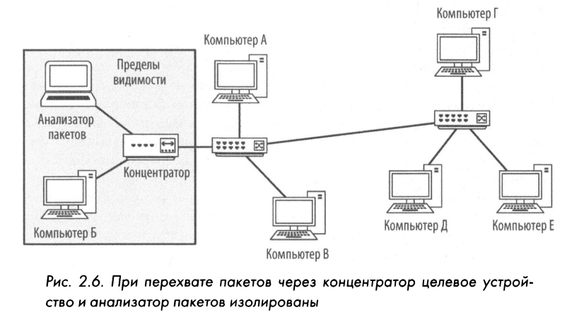
Another way to intercept traffic passing through a target device on a switched network is to capture packets through a hub. In this technique, the target device and the packet sniffer are placed on the same segment of the switched network and connected directly to the hub. Many people consider packet sniffing through a hub to be cheating, but in fact it is a perfectly valid solution when port mirroring is impossible, but there is physical access to the switch to which the target device is connected. To organize the capture of packets through the hub, it is enough to have a hub and several network cables at your disposal.
There is such equipment, connect it as follows.
Find the switch to which the target device is connected and disconnect the latter from the network.
Connect the network cable of the target device to the hub.
Connect another cable connecting your packet analyzer to the hub.
Connect the network cable coming from the hub to the network switch to connect the hub to the network.
You have now placed the target device and the packet analyzer in the same broadcast domain. As a result, all network traffic from this device will be broadcast in broadcast mode. As a result, the packet sniffer can intercept all packets from it, as shown in Fig. 2.6.
In most cases, capturing packets through a hub reduces full-duplex (i.e., bidirectional) data transmission on the target device to half-duplex (i.e., unidirectional). Although this method is not the best method for packet sniffing, it is still the only possible technique in cases where port mirroring is not supported on the switch. However, keep in mind that the hub will also need to be plugged into an electrical outlet, which can be hard to find.
Everyone knows the saying “Why do I need chicken when I can eat steak?” And if you’re from the South, you’re familiar with the saying, “Why do I need liver bread when I can eat a toasted bologna sandwich?” The same applies to choosing between a hub and a network connector for packet capture and analysis.
A network branch is a piece of equipment that can be installed between two network cable points to intercept packets passing between those points. And in this case, as in the case of interception of packets through the hub, equipment is installed in the network that allows interception of packets necessary for analysis. The difference between the method considered here is that instead of a concentrator in this case, equipment specially designed for network traffic analysis is used.
There are two main types of network couplings: aggregated and non-aggregated. Both types of network couplers are installed between two devices to analyze the communication between them. The main difference between a non-aggregated network splitter and an aggregated one is that it has four ports, as shown in Fig. 2.7, and requires separate interfaces to monitor current network traffic in both directions. An aggregated network coupler has only three ports, but it allows you to control the current network traffic in both directions through a single interface. Also, network couplers usually need to be plugged into a wall outlet, although some are also battery-powered, allowing for short-term packet analysis.

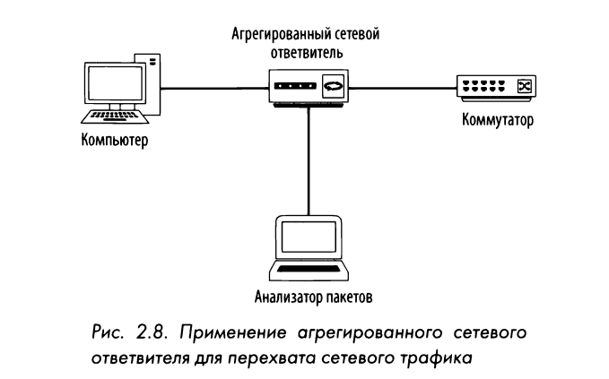
The simplest way is to use an aggregated network coupler that has only one physical management port to analyze bidirectional network traffic. To use an aggregated network hub to intercept all inbound and outbound network traffic from a single computer connected to the switch, follow these steps:
Disconnect the utility from the switch.
Connect one end of the first network cable to the computer and the other end to the input port of the network coupler.
Connect one end of the second network cable to the output port of the network coupler and the other end to the switch.
Connect one end of the third network cable to the management port of the network coupler and the other end to the packet sniffer computer.
The aggregate network coupling must be connected to the network as shown in Fig. 2.8. As a result, the packet sniffer must intercept all incoming and outgoing traffic of the computer connected to this coupling.
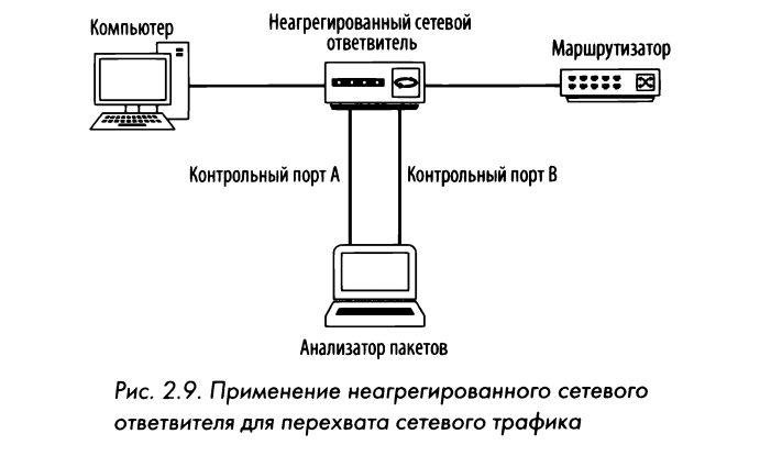
A non-aggregated network coupling is a bit more complicated than an aggregated one. However, it allows for greater convenience when intercepting network traffic. Instead of a single management port used for bidirectional listening, a non-aggregated network splitter provides two management ports. One control port is used to analyze network traffic in one direction (from the computer connected to the network tap), and the other port is used to analyze network traffic in the other direction (to the computer connected to the network tap).
To capture all incoming and outgoing network traffic from a computer connected to the switch, follow these steps:
Disconnect the computer from the switch.
Connect one end of the first network cable to the computer and the other end to the input port of the network coupler.
Connect one end of the second network cable to the output port of the network coupler and the other end to the switch.
Connect one end of the third network cable to the management port A of the network coupler and the other end of the network cable to the same network adapter on the computer acting as the packet sniffer.
Connect one end of the fourth network cable to the control port B of the network coupler and the other end to another network adapter on the packet sniffer computer.
As a result, the non-aggregated network coupling must be connected to the network as shown in Fig. 2.9.
The examples above may suggest that only one device can be controlled using a network coupler. But in reality, many devices can be controlled by being creative with the placement of the network coupler. Yes, if you want complete control over the data exchange between the entire network segment and the Internet, a network coupler can be installed between the commuter vehicle that all the other devices are connected to and the router upstream in the network. This location in the network of the bottleneck allows you to collect the necessary network traffic. This strategy is commonly used in ongoing network security monitoring.
Which type of network coupling is better? In general, aggregated network connectors should be preferred because they require fewer cables and do not require two network adapters to be installed on the packet-sniffing computer. However, if you want to intercept large volumes of network traffic or control traffic that moves in only one direction, a non-aggregated network coupling is better.
Buy network couplings of any size: you can start with simple Ethernet couplings for $150. to enterprise-grade fiber couplings valued in the six figures. I’ve personally used enterprise-grade network couplers from Ixia (formerly Net 0ptics), Dualcomrn, and Fluke Networks, and I’ve been very happy with them, although there are many other great network couplers out there. If you plan to use a network coupler at the enterprise level, make sure that it is sufficiently fault-tolerant. This means that if a network coupler malfunctions or fails, it should still allow packets to pass through without disrupting the network connection at its branch point.
Pollution
One of my favorite methods of intercepting network traffic is infection. The ARP network protocol will be discussed in more detail in Chapter 7 “Network Layer Protocols”, but here is only a brief description of it, which is necessary to understand the features of this technique.
As mentioned in Chapter 1 “Packet Sniffing and Networking Basics” in the OSI model, packet addressing can be done at two layers, layer two and layer three. Layer 2 addresses, or MAC addresses, are used in conjunction with your chosen Layer 3 addressing system. In this book, the third-level addressing system is referred to as IR-aREs according to industry standard terminology.
All devices in the network are interconnected by IP addresses at the third level of the OSI model. And since the switches work on the second layer of this model, they only know the MAC addresses of the second layer. Therefore, in order to exchange packets with each other, devices must include MAC address information. If the MAC address. unknown, it must be obtained from a known third-party IP address to be able to forward network traffic to the appropriate device. And this address translation process is performed using the ARP network protocol at the second layer of the OSI model.
For computers connected to Ethernet networks, it starts when one computer needs to communicate with another. First, the sending computer checks its own computer to see if it already has a MAC address associated with the receiving computer’s IP address. If no such address exists, the sending computer sends an ARP-3anpoc to the link-layer broadcast address ff : ff : ff : ff : EE : ff, which contains the receiver’s IP address, as explained in Chapter 1 “Packet and Network Sniffing Basics” . The resulting broadcast packet is received by all computers on that particular Ethernet segment. Essentially, this packet contains the following query: “What MAC address does the computer with the specified IP address have?”
Those devices that do not match the recipient’s IP address specified in the request simply ignore it. And the computer whose IP address matches the one specified in the request forms an ARP-nakeT response, in which it indicates its MAC address. Thus, the transmitting computer receives the channel-level addressing information it needs to communicate with the remote computer. And it stores this information on its own for quick search.
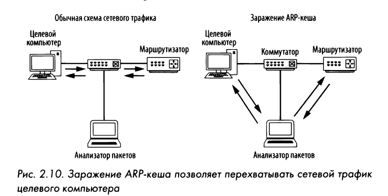
An infection, sometimes called AT-mode, is an advanced form of connecting to a dial-up network in order to eavesdrop on it. The principle of its operation is to send ARP-c006 to an Ethernet switch or router with fake MAC addresses (second layer) to intercept the network traffic of another computer, as clearly shown in Fig. 2.10.
This technique is commonly used by attackers to send misaddressed packets to client systems in order to intercept certain network traffic or cause a denial of service (DoS) attack on the target computer. But this technique can be used and is quite legal to intercept packets from the target computer over a dial-up network.
Before attempting to use the infection, you should purchase the necessary tools and gather some information. In order to demonstrate this technique, we will use the generic Cain 8c Abel oxide protectant. it (http: / /www.oxid. it/), which supports Windows operating systems. Download and install this tool by following the instructions on the website at the above address.
Before using Cain &; Abel, you will need to gather some information including the 1P address of your packet sniffer, the remote system you want to intercept network traffic from, and the router from which the remote system is downlinking.
When you first open Cain &; Avel, you will notice a series of tabs at the top of the main window. After all, infection is only one function of Cain and Abel. For the purposes discussed here, select the Snifer tab. When you click on this tab, you should see an empty table (Figure 2.11).
To populate this table, you will need to activate Cain’s built-in packet sniffer &; Abel and scan hosts on your network.
To do this, do the following:
Click on the second icon from the left with the image of the network adapter in the toolbar.
You will be prompted to select an interface for packet sniffing. Select the interface connected to the network where you will perform the infection If this is your first attempt to use the Cain and Abel tools, select this interface and click OK. And if you have previously selected an interface in Cain Abel, the result of your selection is preserved, and you only need to click again on the icon with the image of a network adapter to select the appropriate interface. (Make sure the button with this icon is clicked to activate Cain & Abel’s built-in packet sniffer.)

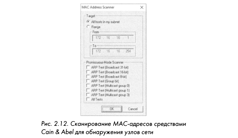
Click the plus (+) button to create a list of hosts on your network. The MAC Address Scanner dialog box will open, as shown in Fig. 2.12. In this window, the AlI hosts on this subnet switch must be selected, or you can specify a range of addresses.
Click OK to continue.
Some Windows 10 users complain that Cain 8c Abel is unable to determine the 1P address of their network interfaces, which prevents them from completing this process. If you have similar difficulties, then when configuring your network interfaces, you will find that their 1P address is 0. 0 . 0. 0.
To get out of this difficulty, do the following:
If the Cain and Abel tool is open, close it.
Enter cpa. cpl in the search bar on the operating system desktop to open the Network Connections dialog box.
First, right-click the network interface from which you want to perform packet sniffing, and then click Properties.
Double-click the Internet Protocol version 4 (TCP/lPv4) option.
Click the Advanced button and select the DNS tab.
Check the box next to Use this connection’s DNS suflX during DNS registration to enable this connection.
Click OK to exit the open dialogs, then restart Cain and Abel.
As a result, the table should be populated with a list of all hosts connected to your network, along with their MAC addresses, 1P addresses, and manufacturer information. It is with this list that you will have to work when setting up the infection.
In the lower edge of the working window Cain &; Abel should display a series of tabs to navigate to other windows under the Snifer heading. So, once you’ve compiled your host list, click on the APR tab to start working on your infection technique in the APR dialog.
Two empty tables will appear in the APR dialog box. At the end of the configuration steps below, the top table will show the devices involved in infecting the ACR cache, and the bottom table will show all the communication between the infected machines.
To set up the infection, follow these steps:
Click first on the empty area at the top of the screen and then on the plus (+) button of the standard Cain toolbar &; Abel.
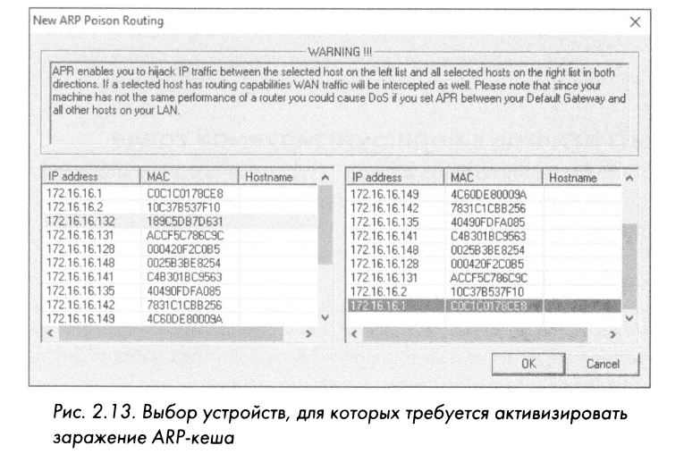
In the window that opens, two selection panels will appear. On the left you will see a list of all the hosts present on your network. If you click on the IP address of the target computer, the panel on the right will list all the hosts on your network except the host that has the IP address of the target computer.
In the right pane, first click on the IP address of the router that directly routes the data stream originating from the target computer (Figure 2.13), and then click OK. As a result, the IP addresses of both devices should appear in the upper table in the main window of the application program.
To complete the process, click on the black and yellow radiation sign, which is located on the standard toolbar. This activates the Cain infection tools &; Abel and will allow your packet sniffer to mediate all communications between the target system and the upstream router.
You should now be able to run your packet sniffer and begin the process of analyzing them. When you are done intercepting network traffic, click the black and yellow radiation sign again to stop the infection.
As a final note about contamination, I would like to say that the purpose of those systems for which this process is implemented should be taken into account. This technique should not be used, in particular, for devices with very high network usage.
An example of this would be a file server that has a 1 Gbps network connection, especially when the packet sniffing system is connected at only 100 Mbps.
When network traffic is routed using the technique presented in this example, all traffic sent to and received by the target system must first pass through the packet sniffer system, thus becoming a bottleneck in the communication process. Such a routing change can have the effect of a denial of service on the analyzed machine, which ultimately leads to reduced network performance and false analysis data. Traffic jams can also interfere with normal SSL communication.
Packet sniffing in a routed environment
All connection methods for switched networks are also available for routed networks. For operation in routed environments, you only need to pay special attention to the location of the packet sniffer when troubleshooting problems that span multiple network segments.
As you should already know, the target device’s broadcast domain extends all the way to the router, where network traffic is forwarded to the next router upstream. If the data needs to pass through several routers, it is very important to analyze the network traffic from all sides of the router.
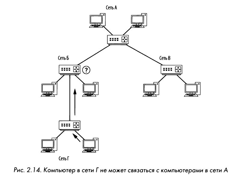
As an example, consider the complexity that can arise in a network with several segments connected through a number of routers. In such a network, each segment communicates with the upstream segment to store and retrieve data. The difficulty we are trying to solve is that the downstream subnet (that is, network D in Figure 2.14) cannot communicate with any of the devices on network A.
If you analyze the traffic of a device on network D that is having difficulty communicating with devices on other networks, you can clearly detect the data being sent to the other network segment, but you may not be able to detect the data coming back. If you change the position of the packet sniffer and join the network traffic analysis on the next upstream network segment (ie network B), you can find that the network traffic is being passed or misrouted by the router router. Although the matter here is somewhat general, an important conclusion can be drawn from it: when working with several routers and network segments, the packet sniffer will have to be installed in different places of the network in order to get a complete picture of what is happening and accurately determine the complexity that has arisen in it.
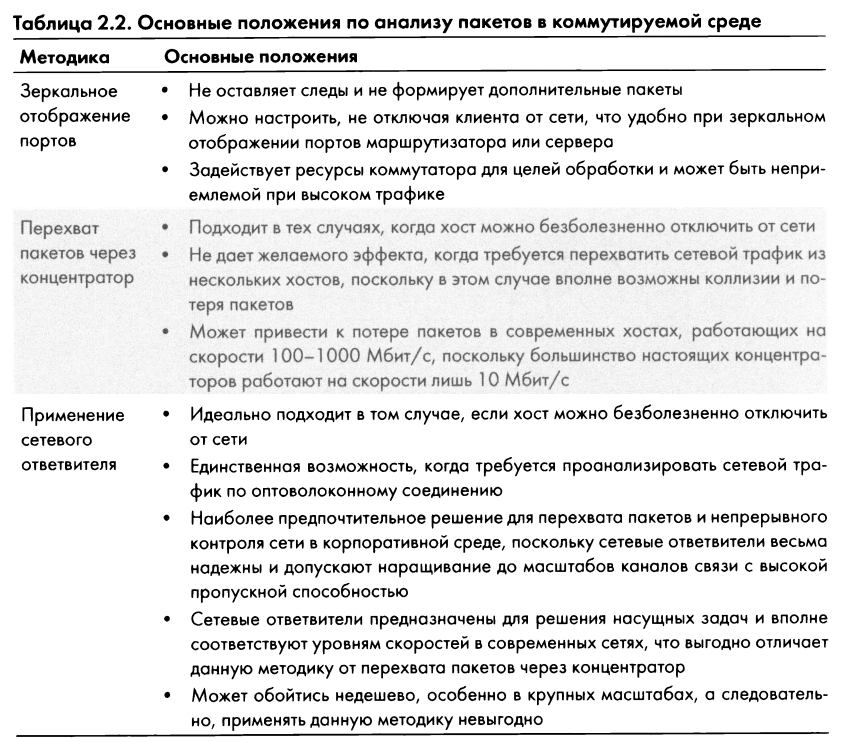
We looked at four ways to intercept network traffic in a switched environment. You can add one more to them, for which it is enough to consider the possibility of installing a program for sniffing packets on one device from which you need to intercept network traffic (this technique is called direct installation). Of these five methods, it is not so easy to choose the most suitable one. Therefore, in the table 2.2 summarizes the main provisions for each method and the corresponding batch analysis method.
Packet explorers should be as hidden as possible. Ideally:

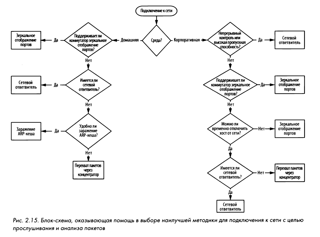
Moving on to practical scenarios in the following sections, we’ll discuss the best ways to capture the required data on a case-by-case basis. Meanwhile, pay attention to fig. 2.15, which shows a block designed to help choose the optimal technique for intercepting network traffic in a specific situation. This flowchart takes into account many factors, starting with whether you want to capture packets at home or at work, but it is only a general guideline and does not cover all possible network connection scenarios for packet sniffing and analysis.
We used materials from the book “PRACTICAL RACKET ANALYSIS” written by Chris Sanders.