
30.04.2023
9 min
2104

Antennas for SDR receivers are a key element that determines the quality of signal reception. It is the correctly selected antenna that allows you to “uncover” the full potential of software-defined radio. The most popular are dipole, loop, pin and directional antennas. Each of them has its own advantages: the dipole is universal, the loop antenna works well in interference conditions, the pin is convenient for urban conditions, and the directional Yagi-Uda provides high gain.
Data transmission on the Internet depends on the bandwidth of the local network, the operation of the router and the characteristics of the communication channels. In the case of radio communication, the antenna is a decisive element for high-quality signal reception.
The principle of its operation is that the transmitting antenna converts high-frequency alternating current into electromagnetic waves that can propagate over a considerable distance. The receiving antenna performs the reverse process – it captures the waves and converts them into alternating current that enters the receiver. The basis of these processes is Ampere’s law.
For effective reception with minimal interference, it is necessary to correctly choose the type of antenna and its location. The specifics of wave propagation in different frequency ranges are also an important factor.
In practice, additional elements are used: matching devices, transmission lines (feeders), filters and low-noise signal amplifiers. If the antenna is installed outside the building, the use of lightning protection devices is mandatory.
This publication is an introduction to the topic of antennas: it discusses the most common options, their parameters, feeder selection, methods of matching with transmission lines, and protection systems.
At the end of the last century, radio amateurs made their own antennas, but now there is no need for this. In online stores and marketplaces, you can buy inexpensive ready-made antennas for almost any occasion.
But how to choose an antenna? There are a lot of different types of antennas, each of which has its own characteristics.
The choice of antenna depends on what frequency range and what type of polarization it is needed for, on your installation capabilities and budget. It is one thing if you are going to install an antenna on a plot near your house or on a roof, and quite another – on the balcony of an apartment building in a dense urban environment.
An antenna of the dipole type or a symmetrical half-wave vibrator is a straight conductor with a gap in the middle, the length of which is equal to half the wavelength of the emitted or received. Through the gap, energy is supplied to the antenna for transmitting antennas or energy is removed in the form of a high-frequency current for receivers.
A high-frequency signal from the transmitter is fed into the gap of the dipole conductor through the power line (feeder). The vibrator works as a resonant system: standing waves of current and voltage are formed along its arms. At the ends of the dipole, the voltage reaches a maximum, while the current approaches zero. In the central part, on the contrary, a maximum of current and a minimum of voltage are observed.
If the antenna is used in the receiving mode, the electromagnetic wave induces a current in the dipole, and then the signal through the feeder enters the receiver. The illustration conventionally depicts a matching transformer and a two-wire line. However, in practice, a coaxial cable is most often used, which requires the use of balancing and matching devices for effective matching of the antenna with the transmission line and minimizing signal losses.
Radio amateurs install a dipole not only inside the house or on its roof, but also use it in field conditions.
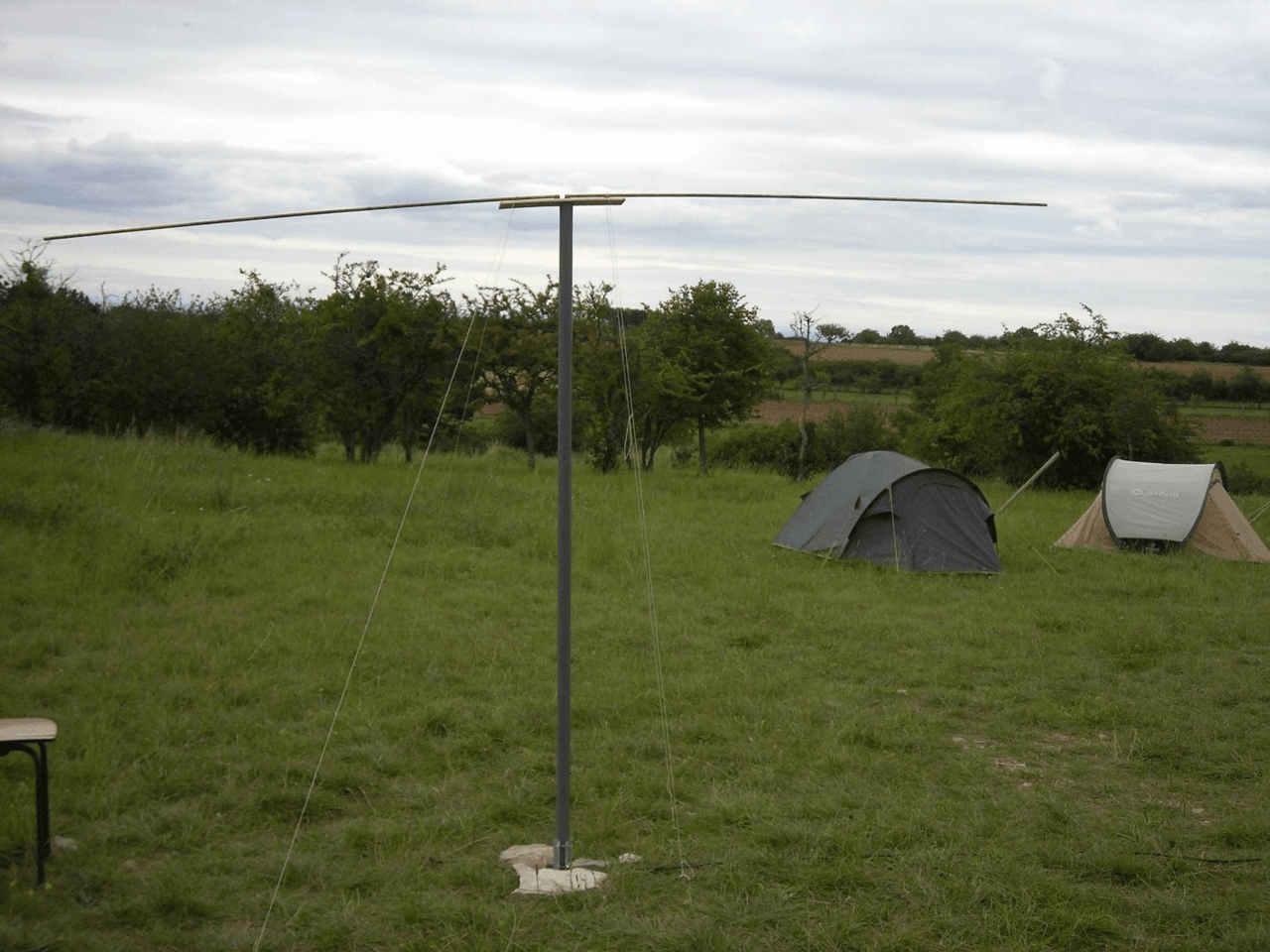
A dipole antenna can take up a lot of space, because its length is half the wavelength. To ensure effective operation, such an antenna must be placed as high as possible. The frequency range of amateur radio communication is quite wide – from 135.7 kHz to 10 GHz and higher, so the question arises whether it is possible to use a half-wave dipole in all these limits.
To calculate the wavelength, the formula is used: λ = c / F, where c is the speed of light (m/s), F is the frequency in hertz. In practical terms, the wavelength in meters is obtained by dividing 300 by the frequency in megahertz. For example, at 30 MHz, the wave will have a length of 10 m, and a half-wave dipole – 5 m. This size is excessive for an apartment, but quite acceptable for a suburban area.
At the lower limit – 135.7 kHz – the wavelength exceeds 2 km, which makes the dipole practically unrealistic to manufacture. In this case, other types of antennas are used. For frequencies of about 144 MHz and 430 MHz, the wavelengths are approximately 2 m and 70 cm, respectively. Antennas of such dimensions can be installed even in an apartment or on a balcony.
Ready-made dipoles for various ranges are available for sale, which are usually supplemented with matching devices for convenient connection.
Antennas are found in the form of a closed conductive circuit in the shape of a square, rectangle or circle. Such an antenna is called a loop vibrator. Fig. 3 shows the half-wave vibrator (dipole) just considered on top, and the loop one on the bottom.
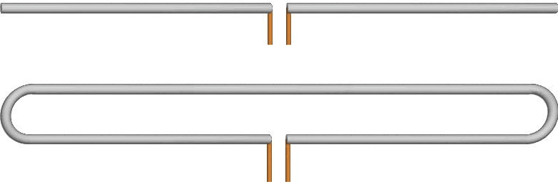
The dimensions for the loop vibrator are chosen for the same reasons as for the dipole. The loop vibrator is used both independently and as part of antennas of more complex designs. Among the advantages of the loop vibrator over the dipole is less sensitivity to interference due to mutual compensation of electrostatic fields. The loop vibrator also has a wider bandwidth compared to the dipole and is convenient for matching with the feeder.
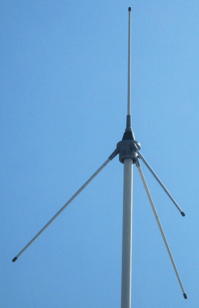
The “vertical pin” or Ground Plain antenna takes up relatively little space and is used very widely for stationary and portable transmitters, as well as receivers. Such an antenna is a vertical quarter-wave conductor.
Given the location on the ground, the Ground Plain antenna pin is a half-wave radiator. In this case, the ground plays the role of a quarter-wave vibrator, which is missing due to the mirror image of the antenna. Fig. 5 shows the installation of such an antenna in an open field.
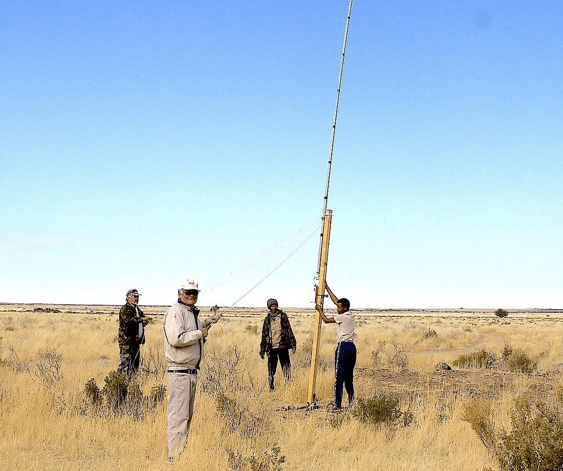
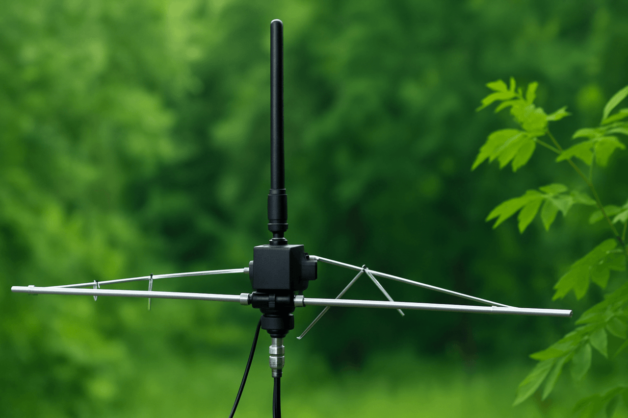
As you can see, despite the long length of the pin, the area occupied by the antenna is small. Fig. 6 shows a small vertical pin, which is sold complete with the RTL-SDR V4 receiver and is well suited for FM radio.
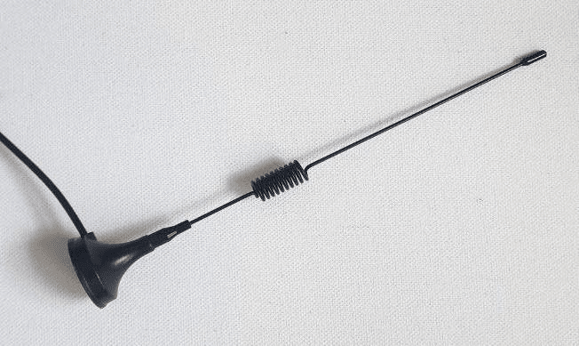
The base of the antenna has a magnet for attachment to a metal surface, such as a window visor, balcony, or car roof.
Closer to the base, the antenna has an extension coil. It adds inductance and shifts the resonance frequency to the lower frequency range. As a result, the antenna length can be less than a quarter of a wavelength. Vertical rods of various lengths are available, in particular for the 10-meter range, where long-distance truck drivers communicate with each other. Telescopic antennas are often used, the length of which can be adjusted.
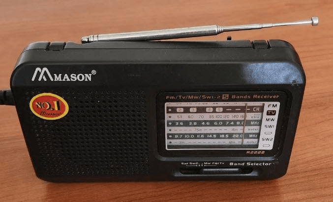
Telescopic antennas are used not only in receivers, but also in portable radios. If the antenna is mounted far from the ground on a mast, it can be equipped with counterweights that act as the ground.
In handheld radios, the human body acts as the ground for the rod antenna.
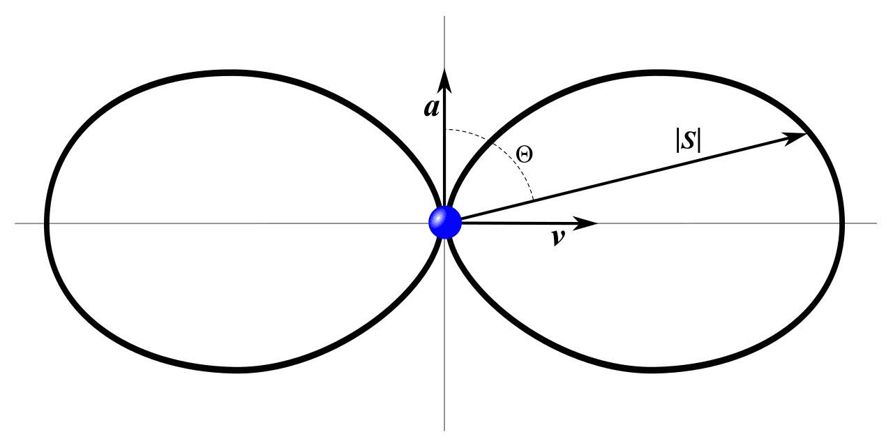
The radiated power of a half-wave dipole connected to a transmitter depends on the direction. The maximum power is radiated perpendicular to the dipole, and there is practically no radiation along the dipole.
A horn antenna in the horizontal plane is characterized by omnidirectionality, but in the vertical plane and when the angle of inclination changes, the radiation intensity decreases.
Directional antennas have a main lobe of the radiation pattern, in the direction of which the main part of the energy is transmitted. In addition, there are side lobes with weakened radiation. Similarly, during reception: the antenna receives the maximum signal from the main lobe, and from the side directions – much weaker.
A half-wave dipole forms two lobes located perpendicular to the antenna conductor. This means that the signal will be received most strongly in these directions, while from other directions the signal level will be lower. Due to this, directional antennas help reduce the level of interference from unwanted sources that are outside the main directional lobe.
The directional Yagi-Uda antenna, developed in 1926, consists of a half-wave dipole, a reflector, and one or more directors. Fig. 10 shows a three-element Yagi antenna, which has a radiating element A, a reflector R, and one director D.
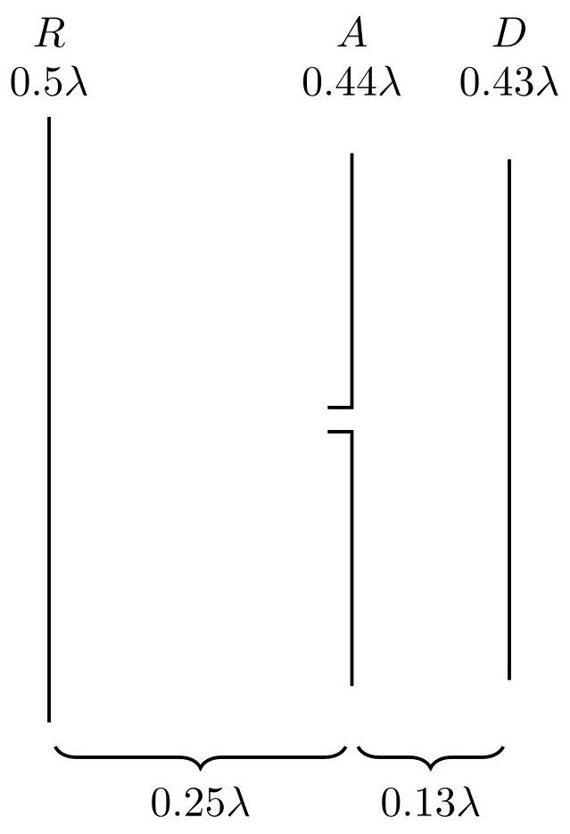
The size of the elements depends on the wavelength λ.
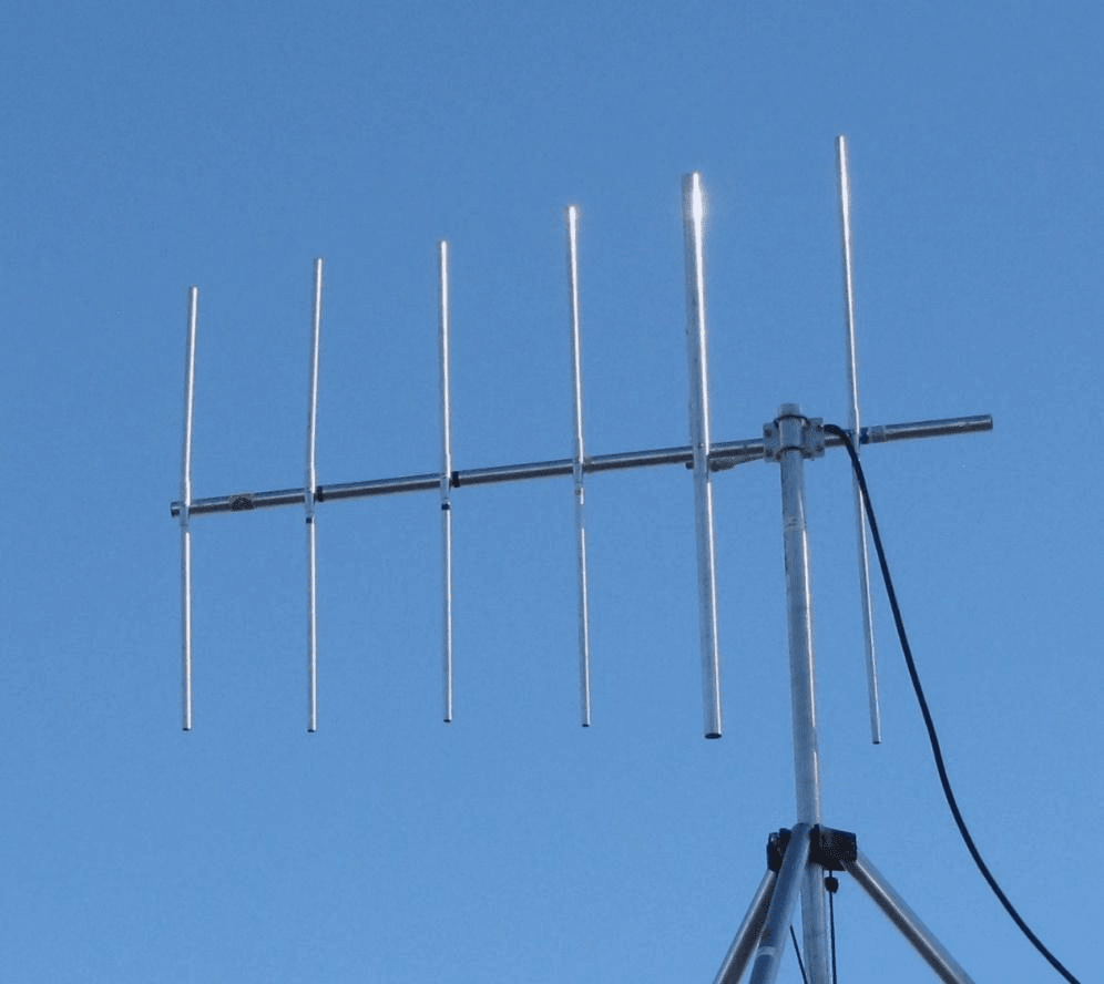
Fig. 11 shows a multi-element antenna with four directors. The more directors, the higher the antenna gain, but its bandwidth.
The Yagi-Uda antenna is characterized by high directivity, but it also has disadvantages: a narrow bandwidth, sensitivity to the accuracy of manufacturing and arrangement of elements, difficulty in tuning (requires special equipment) and significant dimensions in the short-wave range. At the same time, ready-made models for different frequencies are available on sale.
Due to the interaction of waves from the antenna elements, maximum radiation in the direction of the directors is achieved during transmission and the highest sensitivity in the receiving mode. Side radiation is strongly suppressed, which reduces the influence of interference.
Such antennas are used by radio amateurs on short and ultrashort waves, in wireless communication systems and for receiving television signals – both analog and digital.
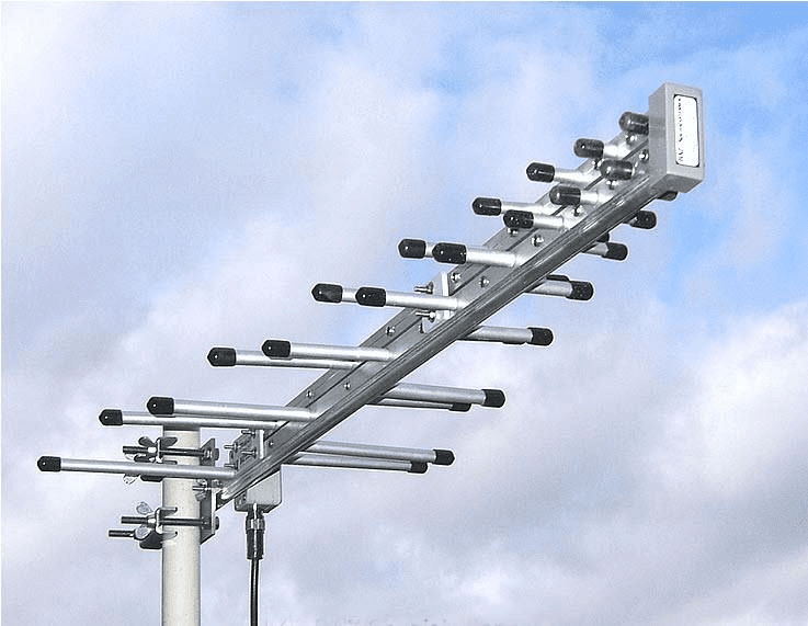
If a directional broadband antenna is needed, you can use the so-called log-periodic antenna. It consists of a set of dipoles located along two rods and connected alternately. In this case, the lengths and distances between elements decrease logarithmically.
In the long, medium and short wave ranges, the dimensions of dipole and rod antennas become too large for installation in residential conditions or on a balcony. The use of shortened rods is possible, as in portable radio stations, but their efficiency is significantly lower compared to full-size antennas.
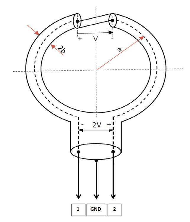
An alternative option in these ranges is loop antennas (Loop antenna) – conductors formed into one or more turns of round, rectangular or other shape.
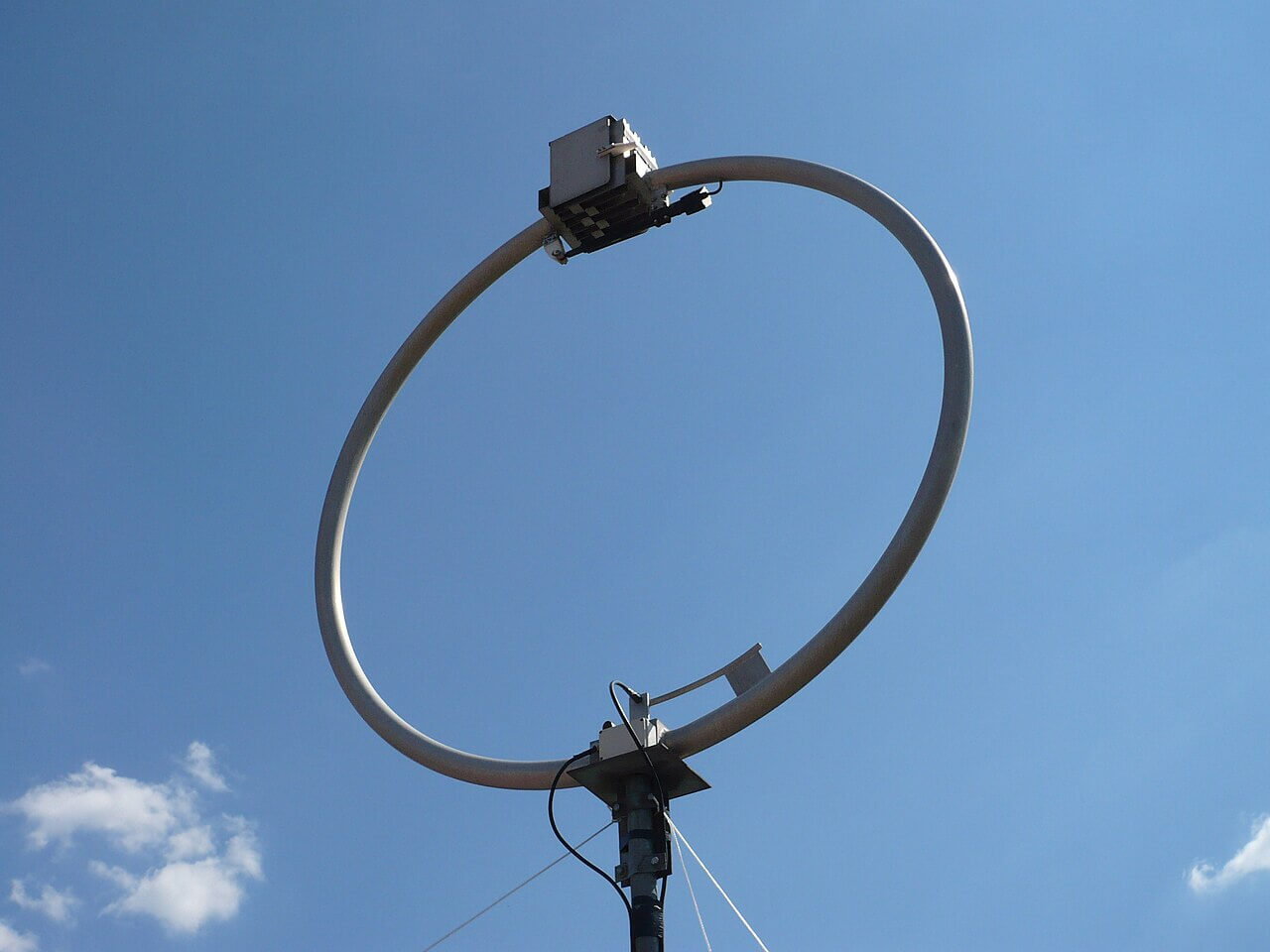
The more turns in a loop antenna, the higher its sensitivity becomes. Among the advantages of such antennas, it is worth noting compactness, high directivity and good immunity to interference. The main disadvantage is the need to tune to the resonant frequency.
Loop antennas are often called magnetic, because they respond primarily to the magnetic component of the electromagnetic field. There are varieties of magnetic loop antennas in which the current in the turns is distributed along a closed loop in the form of a Mobius strip.
A long wire antenna is exactly what it sounds like, as it is a wire longer than a quarter of a wavelength. As the length increases, both the gain and directivity increase.
The advantages of this antenna include its simple design, low manufacturing costs, and the ability to operate at multiple frequencies. The main disadvantage is its large size, making it more convenient to install such antennas in a suburban area.
In a multi-story building, you can throw the antenna wire from the lower floors onto a tree standing next to the house, but make sure that there are insulators at the end and at the beginning of the wire. Also check that there are no high-voltage power lines nearby.
If the antenna length is less than the wavelength, then the directivity pattern is the same as that of a dipole – radiation in lateral directions. If the antenna length exceeds several wavelengths, then the antenna radiates to the side at an angle to the wire.
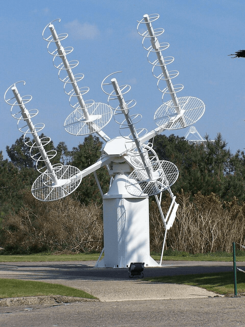
A very interesting type of antenna is a spiral antenna. This antenna is a wire wound in the form of a spiral. Fig. 16 shows a rotating unit of spiral satellite antennas.
The main parameters of an antenna determine its efficiency and suitability for specific operating conditions. Key indicators include gain, polarization, impedance, radiation directionality, and operating frequency range. Physical characteristics are also important – dimensions and weight, which affect the choice of installation location.
This parameter determines the directivity and efficiency of radiation. It shows how many times the radiated (or received) power density in the direction of the main lobe exceeds the same indicator of the reference antenna.
Relative to an isotropic radiator, the gain is expressed in dBi.
Relative to a half-wave dipole, it is expressed in dBd.
There is a difference of 2.15 dB between these values. For example, a half-wave dipole has 2.15 dB more gain than an isotropic antenna. It is worth considering that directional antennas with high gain do not create additional power, but only concentrate it in a certain direction, increasing the communication range.
Radiation can have different types of polarization — linear or circular.
Linear can be vertical, horizontal or inclined. Vertical is used in FM radio and portable radios, horizontal in television broadcasting and microwave communication channels.
Circular polarization is common in satellite communications, drones and radar. It can be right-handed (rotation of vectors clockwise) or left-handed (rotation counterclockwise).
Thus, when choosing an antenna, it is important to consider not only its design, but also the parameters that determine the quality of operation in the desired frequency range and specific conditions of use.
Fig. 17 demonstrates linear and circular polarization.
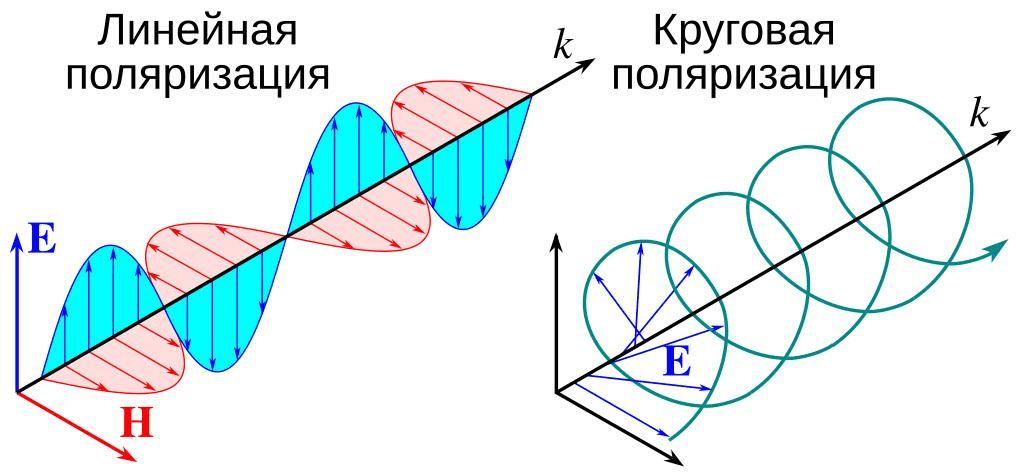
For the radio channel to operate effectively, the polarization of the transmitting and receiving antennas must match.
Matching the antenna to the feeder is critical for the effective operation of the system. The key parameter is the input impedance of the antenna — the complex resistance at the point of connection of the feeder at the operating frequency. It is impossible to measure it with a conventional ohmmeter, this requires specialized equipment.
Since antennas are usually installed at a height and at a distance from the receiver or transmitter, the connection is made through a feeder — most often a coaxial cable. To obtain the maximum signal level at the receiver or to ensure full radiation from the transmitter, it is necessary to match the antenna to the feeder, and the feeder to the equipment. In case of mismatch, signal reflections occur, which reduces the efficiency of operation.
Typical input resistance values:
half-wave dipole — about 60–73 Ohms;
quarter-wave pin — about 36 Ohms;
loop antennas — from a few Ohms to tens of kOhms, depending on shape, size, number of turns, and frequency.
The most common coaxial cables have a characteristic impedance of 50 Ohms or 75 Ohms. Ready-made antennas usually have matching circuits, while homemade versions need to take care of this separately.
To assess the quality of matching, the standing wave ratio (SWR) is used – the ratio of the maximum voltage of the standing wave to its minimum. The SWR value = 1 indicates perfect matching, the absence of a reflected wave and maximum efficiency. The higher the SWR, the greater the energy losses in the feeder.
Since most antennas have a symmetrical design, and coaxial cable is asymmetrical, balancing devices are used to correctly combine them.
Fig. 19 shows four examples of impedance matching schemes for a coaxial cable and an antenna.
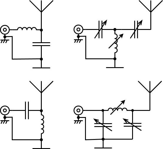
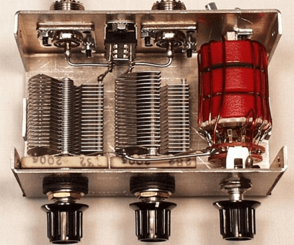
The upper left shows the circuit used when the antenna resistance is greater than the cable resistance, and the lower left shows the circuit used when the antenna resistance is less than the cable resistance. The T-shaped and P-shaped circuits (upper right and lower right) are suitable for a wide range of impedance matching. Fig. 20 shows an antenna tuner that performs the function of matching the antenna and the feeder.
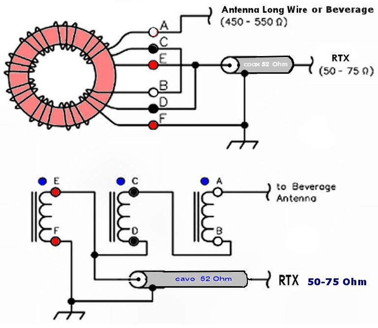
For a long wire antenna, it is necessary to match the high impedance of the antenna, which is about 500 Ohms, and the impedance of the feeder (usually 50 Ohms). This can be done using a matching transformer – a balun (Fig. 21).
When installing an outdoor antenna, for example on the roof of a house or when stretching a wire between a house and a tree, it is imperative to take care of lightning protection. Otherwise, during a thunderstorm, damage to the radio equipment, a strong electric shock or even a fire may occur.
The metal elements of the antenna should be connected to the ground using a thick wire or metal strip. This grounding should be connected to the general grounding circuit of the building.
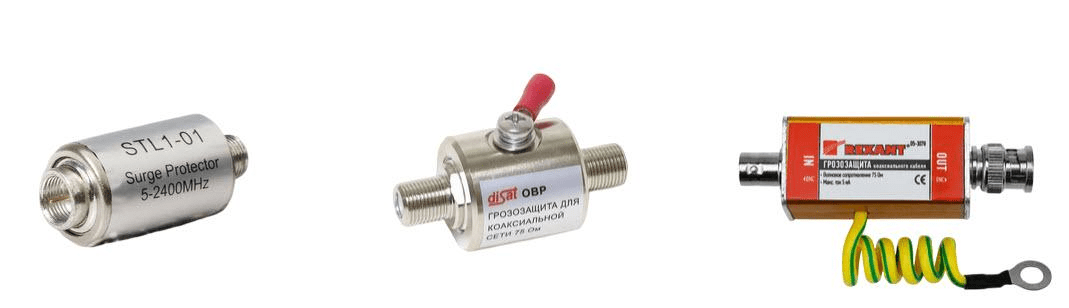
The coaxial cable must be connected to the ground through a lightning arrester. For this, special devices are used that protect the connected equipment from lightning impulses. Such protection devices are commercially available in various versions and can significantly increase the safety of operating the antenna system.
As for grounding, different schemes are used for different types of antennas.
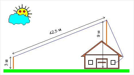
For a dipole antenna, it is recommended to install a lightning rod so that the antenna is within the 45° protection angle.
A vertical pin also requires a lightning rod, and it is additionally necessary to ground the mast and base. Similar measures should be applied to a “long wire” antenna, including grounding the coaxial cable braid.
A Yagi antenna is protected by grounding the mast and cable, while a satellite dish provides for grounding the bracket and support.
Antennas are a key element of any radio communication system — the quality of signal reception and transmission depends on their design, parameters, and installation conditions. Dipole, loop vibrator, vertical pin, Yagi antenna, frame or long wire — each type has its own advantages, disadvantages, and scope.
When choosing an antenna, it is important to consider the operating frequency range, gain, polarization, feeder matching, and installation location. No less important is the issue of safety: external antennas necessarily require lightning protection and high-quality grounding.
Today, radio amateurs can either make their own antennas or purchase ready-made solutions for any budget and task. The main thing is to choose the antenna that best suits the operating conditions, and then the connection will be reliable even in difficult conditions.