
02.11.2023
3 min
1764

In the world of network technologies, the concepts of bridge and switch are often confused – even experienced specialists sometimes use these terms as synonyms. However, in modern data centers there is a clear functional boundary between them, and this article will help you understand it.
The material considers how a bridge performs the role of a logical layer, transparently connecting nodes within one L2 segment, and a switch is a physical device that implements this function and often also works as a router at the L3 level.

The difference between these two networking devices has been a mystery to me for quite some time. For a while, I used the words “bridge” and “switch” interchangeably. But as I delved deeper into networking technology, I began to notice that some people tend to think of them as quite different devices… So maybe I’m completely wrong? Maybe the phrase “bridge, also known as a switch” is too vague?
Let’s try to figure it out!
There is a good book called “Understanding the Internals of Linux Networking.” It has a whole chapter on bridges. Among other things, it states that a bridge is the same as a switch.
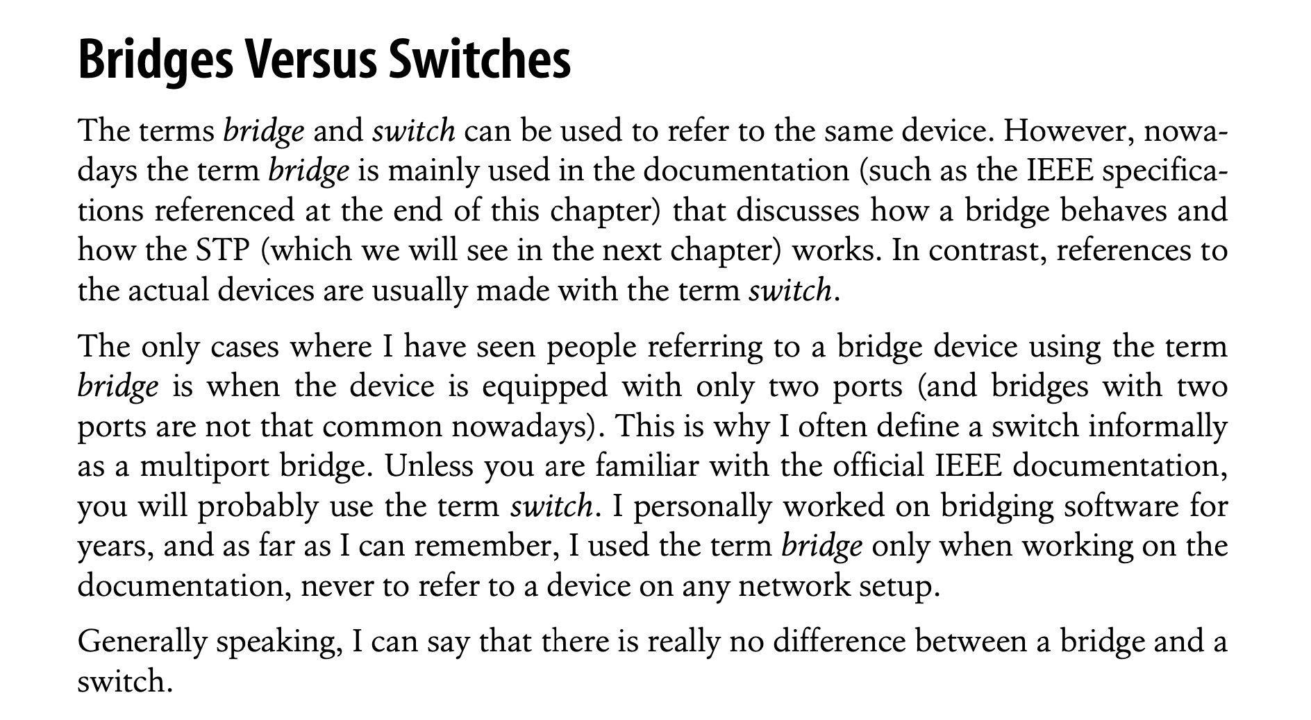
My conclusion from this book was this:
When we say “bridge”, we mean the logical function of the device.
When we say “switch”, we mean the actual physical device that performs that function.
So, what is this function?
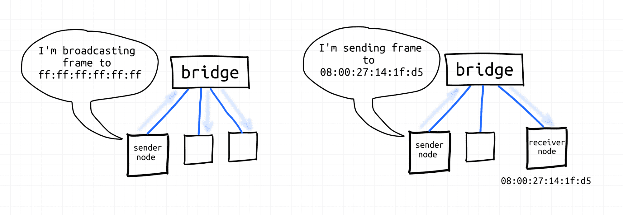
Bridges transparently connect network nodes into second-level segments, creating second-level broadcast domains. Nodes on the same segment can exchange link-layer frames with each other using either unicast (MAC) or broadcast addresses.
Bridges can connect not only end nodes, but also subsegments. That is, you can connect a bridge to a bridge, for example, by doubling the maximum segment size.
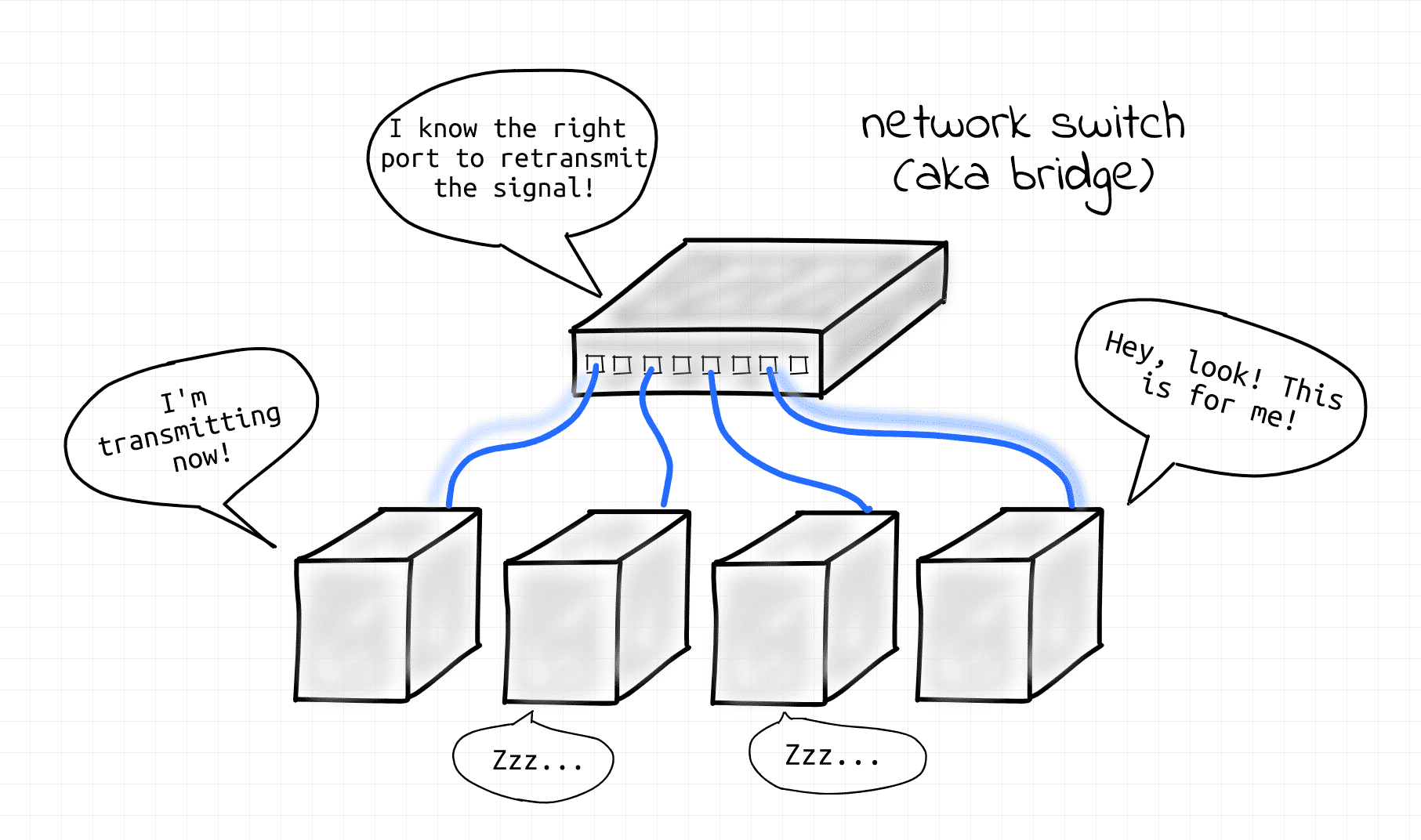
The fact that bridges perform their function transparently means that from the point of view of network participants, bridges do not exist. Nodes simply send frames to each other. The bridge’s task is to find out which node is reachable from which port and forward Ethernet frames accordingly.
The evolution of network devices has a long history. Supposedly, bridges were originally two-port devices that connected two L2 (or L1?) network segments into a larger L2 segment. Hence the name bridge. Then they evolved into multi-port devices, but the name stuck. Regardless of the number of ports, such devices were invisible to network participants – bridges always perform their function transparently.
Then the hardware evolved even more, and today it is difficult to find purely hardware bridges, especially in a serious context of use (see the next section). However, the need for the logical bridge function has remained unchanged. In the real world, this function is often performed by switches. In the virtual world, a virtual Linux bridge device.
What helped me understand the difference was that I started thinking in terms of the following logical network devices:
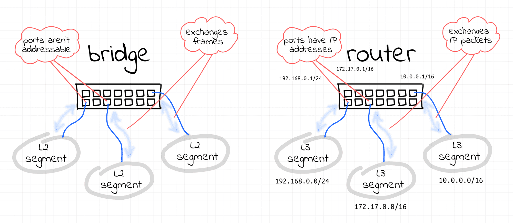
A bridge is a transparent Layer 2 device that forwards frames within a single L2 segment.
A router is an opaque Layer 3 device that forwards IP packets between multiple Layer 3 segments.
So, how can you organize a fairly large LAN? Theoretically, it is possible to connect several bridges together to expand the broadcast domain to hundreds (or even thousands) of nodes. But it turns out that giant broadcast domains are quite difficult to manage. Obviously, in the real world, huge domains often lead to huge failures.
So, instead of a huge broadcast domain covering the entire data center, it is better to have smaller isolated L2 segments that can communicate with each other through… L3 routers! Back to switches…
Modern network switches used in data centers are quite advanced devices. They can work as bridges. Or as routers. Or… some of their ports can work in bridge mode and some others in router mode. I would think a little and say that we are probably talking about multi-layer switches here.
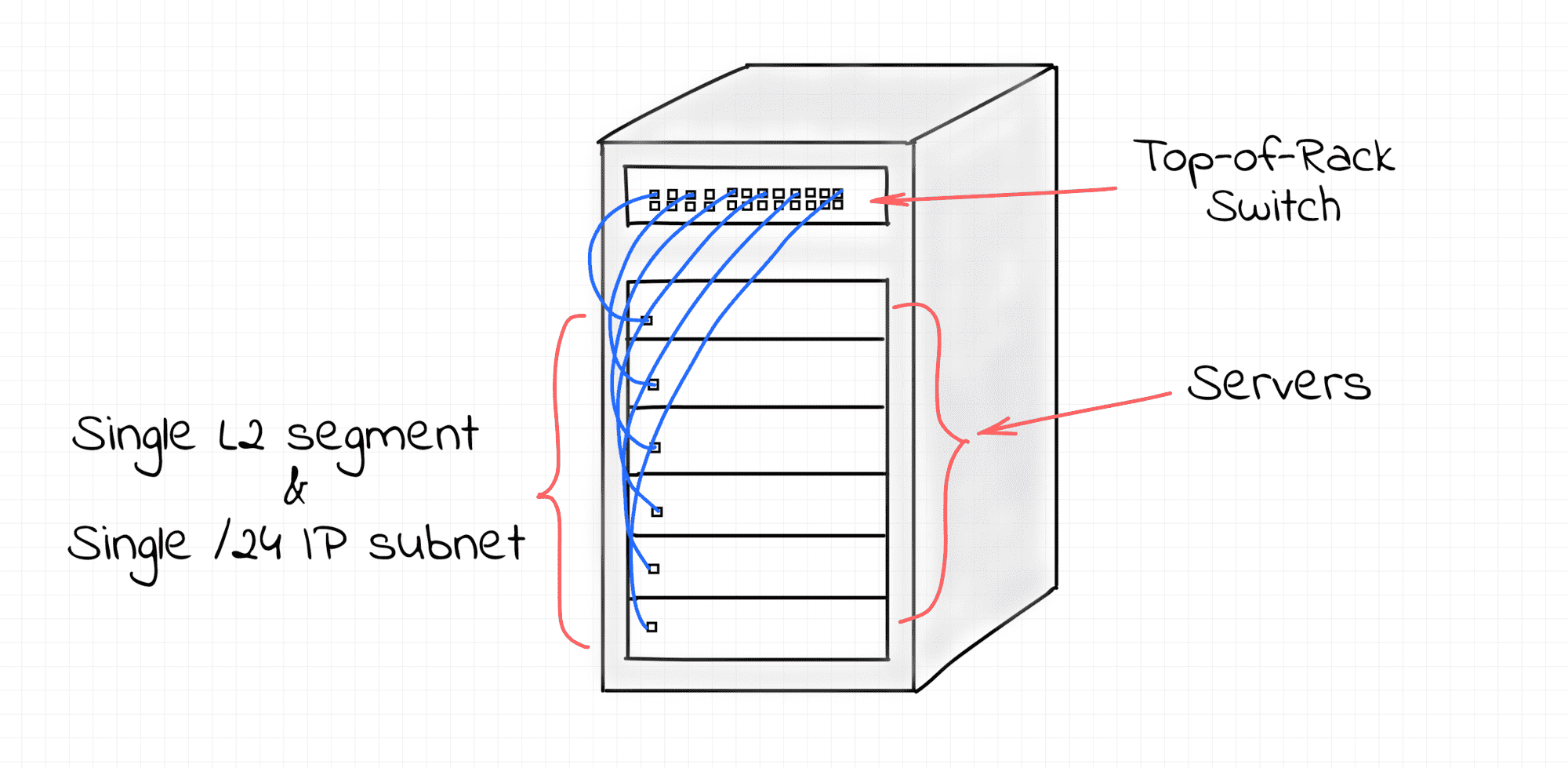
In the configuration I’ve seen, all servers in a single rack are on the same /24 IP subnet and connected to a single switch.
Facebook seems to have a pretty similar DC architecture. I haven’t done much research, but this article about Load Balancers indirectly confirms this.
Such a switch is called a Top of Rack (TOR). For these servers, the TOR switch behaves like a canonical transparent multiport bridge. That is, like a pure Layer 2 device. And the rack forms L2 and L3 segments of equal size.
However, the L3 segments formed by separate racks must be combined into a network. To do this, one of the remaining ports of the TOR switch is configured to operate in L3 mode. Unlike L2 ports, this means that this port is an addressed network node with an IP address. It is then connected to a higher-level switch.
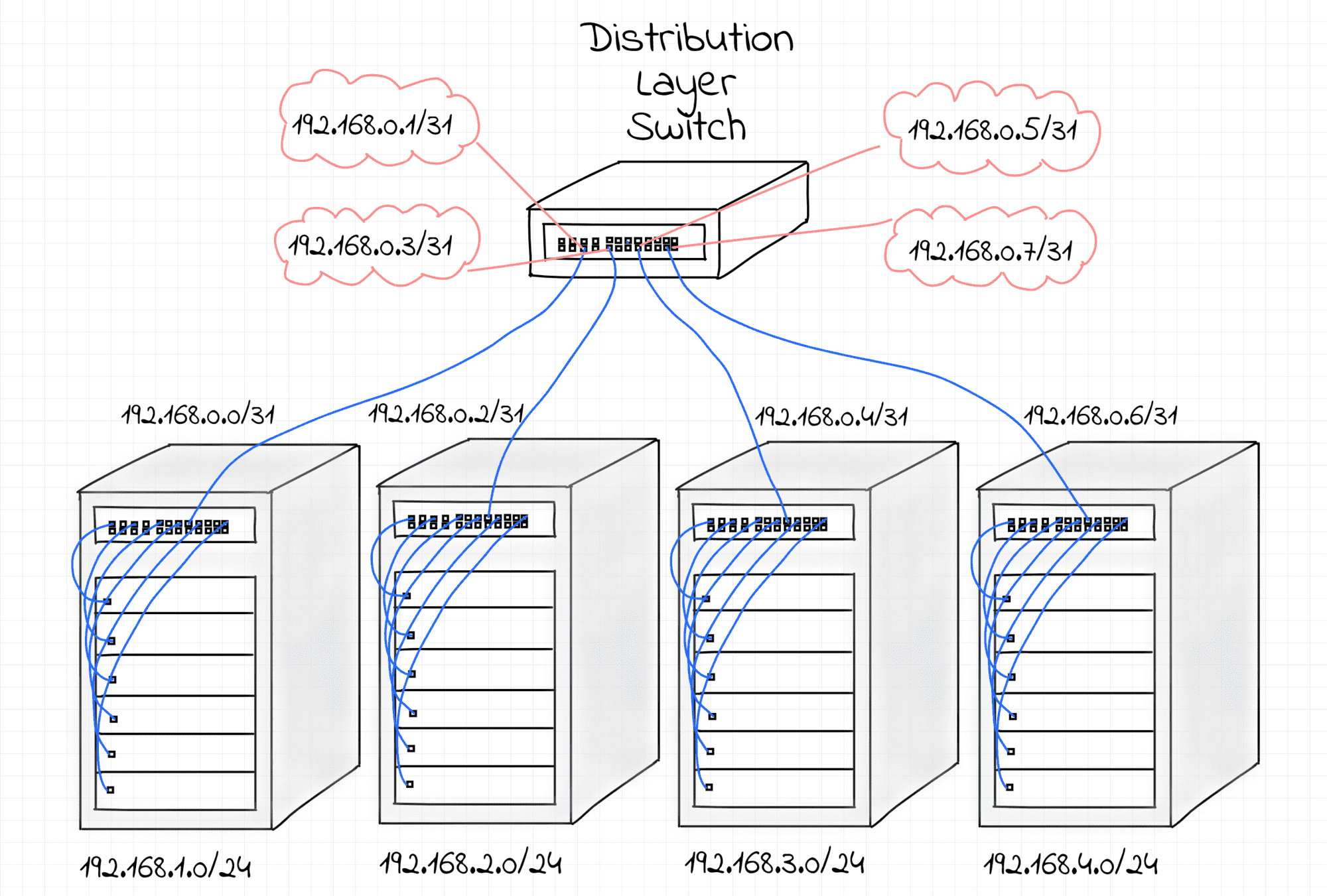
In fact, each TOR switch is usually connected to at least two higher-level switches. First, to provide some redundancy in case of hardware failure. But also, if these multiple physical connections are combined into a single logical link, it can increase the resulting bandwidth.
These higher-level switches in the diagram above are called distribution layer switches. In the network I was looking at, the switches at this level act as pure L3 routers. So, each port of the distribution layer switch is a full-fledged Layer 3 device with an IP address assigned to it.
TOR switches can be thought of as complex devices with a bridge (with dozens of ports) and a router (with only 2 ports) inside. Distribution layer switches can be thought of as multi-port L3 routers. Like real multi-port routers with 48 or 64 ports! The router on a TOR switch knows only two routes – to the rack subnet and the default router, which points to its distribution layer switch. And each distribution layer switch knows many routes. Each rack connected to it has its own /24 IP subnet, and this switch acts as a border router for dozens of such subnets.
However, physically, there is no difference between the first and second types of switches! They all look the same, but are simply configured differently.
In addition to these 48 (or 64) ports, the switches have one or two out-of-band ports.
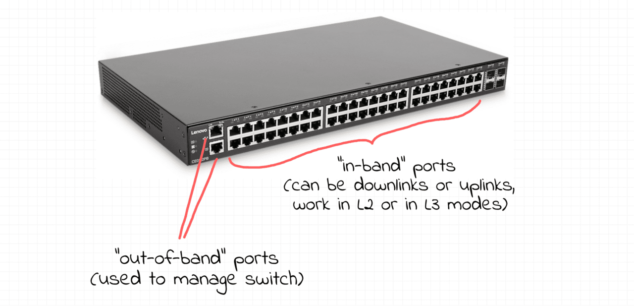
Regardless of the mode of other ports, out-of-band ports always operate in L3 mode. You can log in to the switch using the IP address of the out-of-band port. This is necessary for managing the switches, since configuring the switches through regular ports would be simply dangerous. Imagine if you messed up some commands and locked yourself out of the switch?
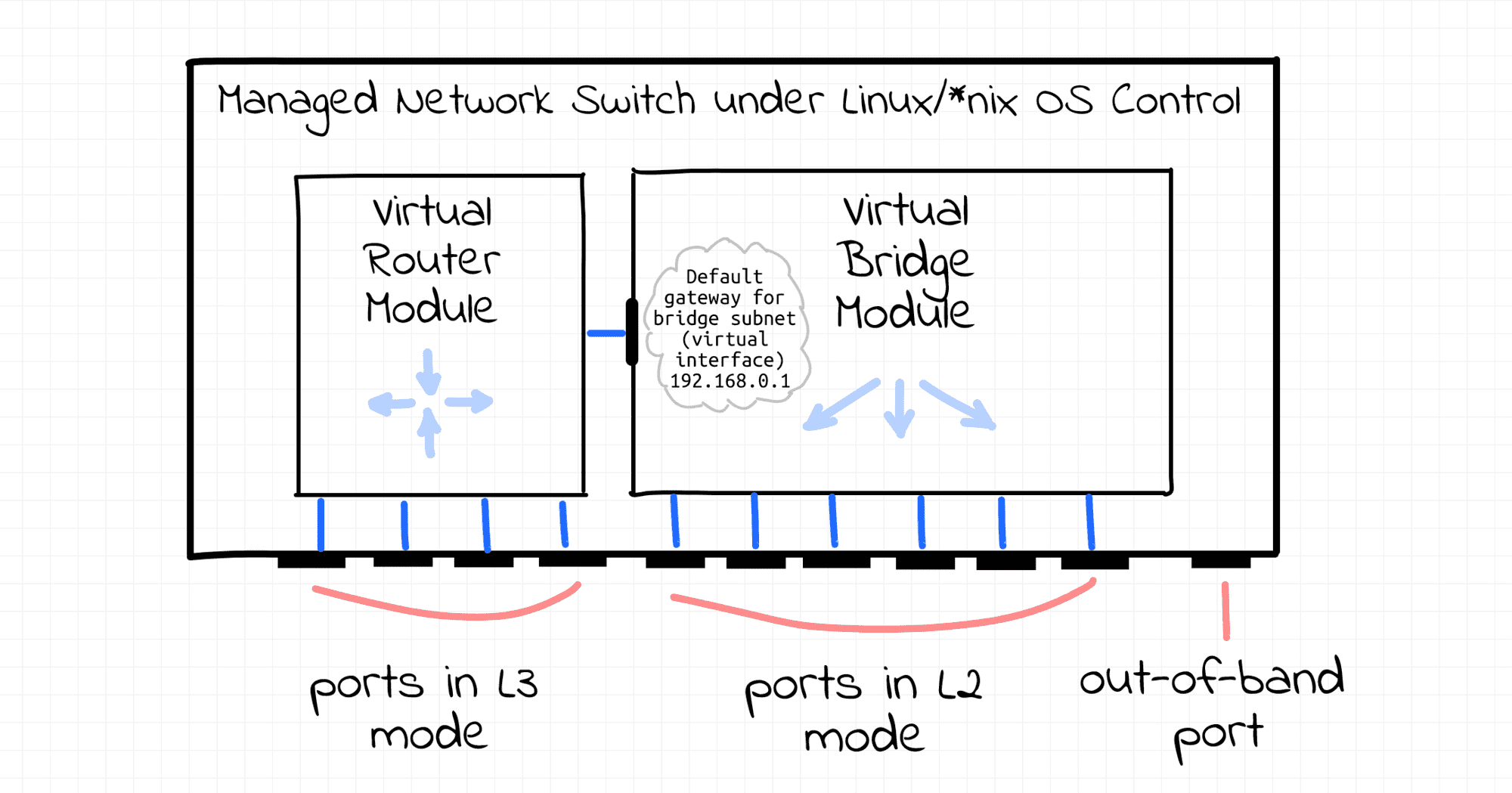
I wonder what it would look like if you connected to the switch via ssh ? Surprise, surprise! It’s Linux! Or FreeBSD. Or some proprietary Unix-like OS. That is, you can configure the switch through a traditional ssh session using well-known iproute2 tools such as ip and/or bridge.
From a management perspective, each port on the switch looks like a traditional network device. You can connect some ports to a Linux virtual bridge, assign IP addresses to other ports, configure packet forwarding between ports, set up a routing table, etc. So, you can imagine a switch as a Linux server with many network ports. And it’s up to you how you configure them. All the traditional Linux capabilities are at your disposal. But, of course, from a hardware perspective, switches are highly optimized packet processing devices.
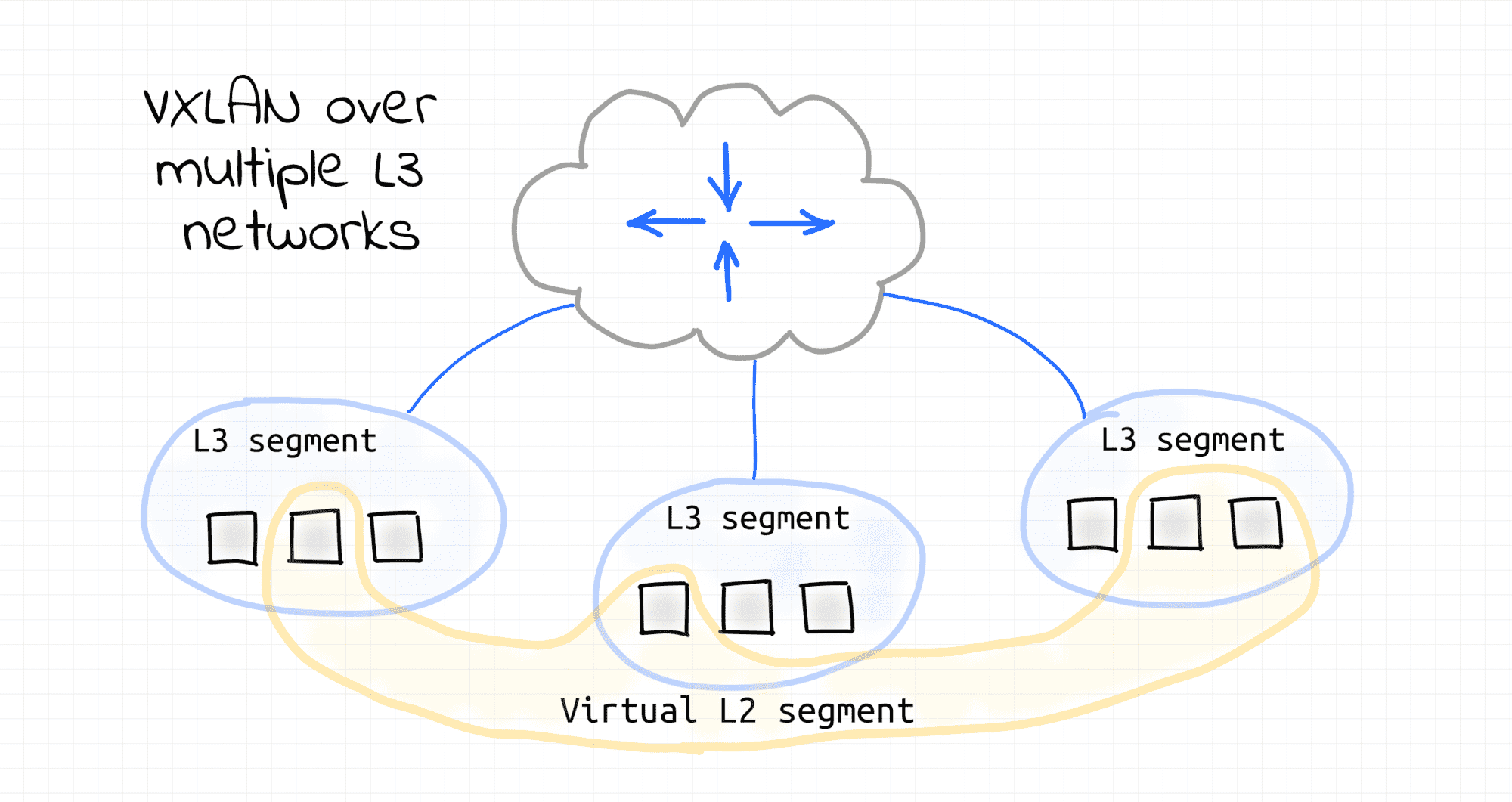
So what happens with broadcast domains? Can we have a broadcast domain that spans multiple racks? Of course! VXLAN to the rescue! Up until this point, I’ve been describing the physical network configuration of a data center. But you can configure any network overlay on top of it, making it tailored to the needs of your end users.
Despite the common confusion between the concepts of bridge and switch, the essence is as follows: a bridge is a logical function of connecting nodes within a single layer (L2) segment, while a switch is a physical device that performs this function, often with advanced routing capabilities (L3).
Modern network switches have become universal devices that can work as bridges, routers, or hybrids, depending on the configuration. In a typical data center infrastructure, a TOR (Top-of-Rack) switch plays the role of a bridge for servers within a rack, and distribution layer switches are full-fledged routers for connecting different subnets.
Each port in such devices is a flexible interface that can be connected to a Linux bridge, assigned an IP, or changed its operating mode. All this makes modern switches logically similar to multi-port servers optimized for maximum traffic processing speed.
And although the terms bridge and switch have historically overlapped, today the correct understanding of their purpose is not semantics, but the basis for competent network design.
👉 In short: a bridge is a function. A switch is a tool that performs it. Sometimes even much more.