27.09.2025
7 min
991

Nixie clocks are a unique combination of retro aesthetics and modern electronics. In the first part, we tell you how the idea of creating your own Nixie clock came about, why these lamps still fascinate, what requirements apply to the first version, and how the logic of the indicators is formed. You will learn about choosing the time display format, using a PIC16 microcontroller, a separate power supply, and the features of controlling cathodes through high-voltage registers. This is an ideal immersion for beginners in DIY electronics.
Gas discharge indicators immediately impress with their unusual aesthetics and brightness. They have features, among which is the need to use absurdly high constant voltage.
A search on the Internet showed that stocks of such lamps from Eastern Europe are still available. Today, the most common application of these components is in products assembled by enthusiasts and offered for sale.
There are specialized resources in the open access, where the principles of operation of gas discharge indicators and their control are discussed in detail. Among them are EEVBLOG, Fran Blanche, Dalibor Farny, і Threeneuron. Thanks to the availability of such information, the development of your own circuits and designs has become much easier.
Familiarization with this, albeit impractical, but incredibly beautiful technology inevitably arouses interest in creating your own clock on gas discharge indicators.
All project files: Nixie_Clock_ Files.zip
PIC source code: Nixie_main_v3.c
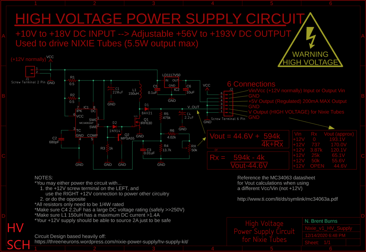
High voltage power supply circuit diagram: Nixie_v1_HV_Supply.sch
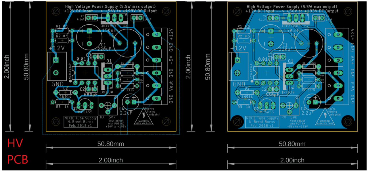
High-voltage power supply printed circuit board: Nixie_v1_HV_Supply.brd
Clock diagram: Nixie_v1.sch
Clock printed circuit board: Nixie_v1.brd
Using the software: MPLAB X IDE | EAGLE
Printed circuit board manufacturer: JLCPCB
After studying the clocks that other radio amateurs had assembled and posted online, the requirements for the first version of the project became clear.
The clock logic should be controlled by a simple microcontroller – PIC16, PIC18 and the like – and not an excessive solution like a single-board Raspberry Pi.
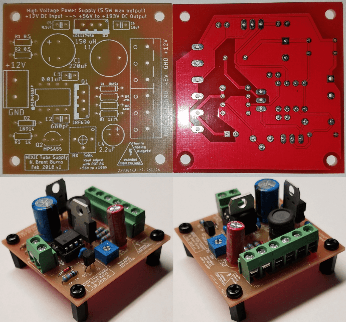
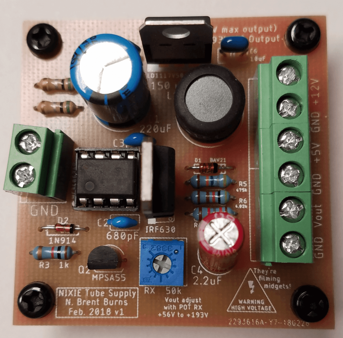
It is better to make the high-voltage power supply as a separate circuit and printed circuit board. This will give the project modularity and flexibility in case the high-voltage part is needed for other purposes. In addition, the presence of high voltage and noise from the generator on the main board with indicators will be limited as much as possible. Finally, it will be possible to reduce the size of the main board of the clock and place the power supply board behind it. It is not visible in the finished case.
The clock will be 6-digit, in 12-hour format – H1 H0: M1 M0: C1 C0.
A small RGB LED will be placed under each gas-discharge indicator for additional backlighting. The red, green and blue channels of each LED will be controlled by three push-button switches with a latch – this will result in mixed colors.
Setting the time – using a rotary encoder. Pressing puts the system into setup mode. Turning sets the hours. The next press – minutes, another – seconds. The last one will return the clock to normal operation.
A main power switch with a latch is provided. It will not turn off all power to the circuit, but only the high voltage supplied to the gas-discharge indicators. This way you can turn them off for the night without stopping the clock.
The entire circuit is powered by a ready-made low-voltage AC/DC adapter.
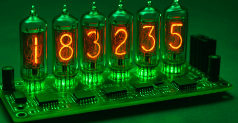
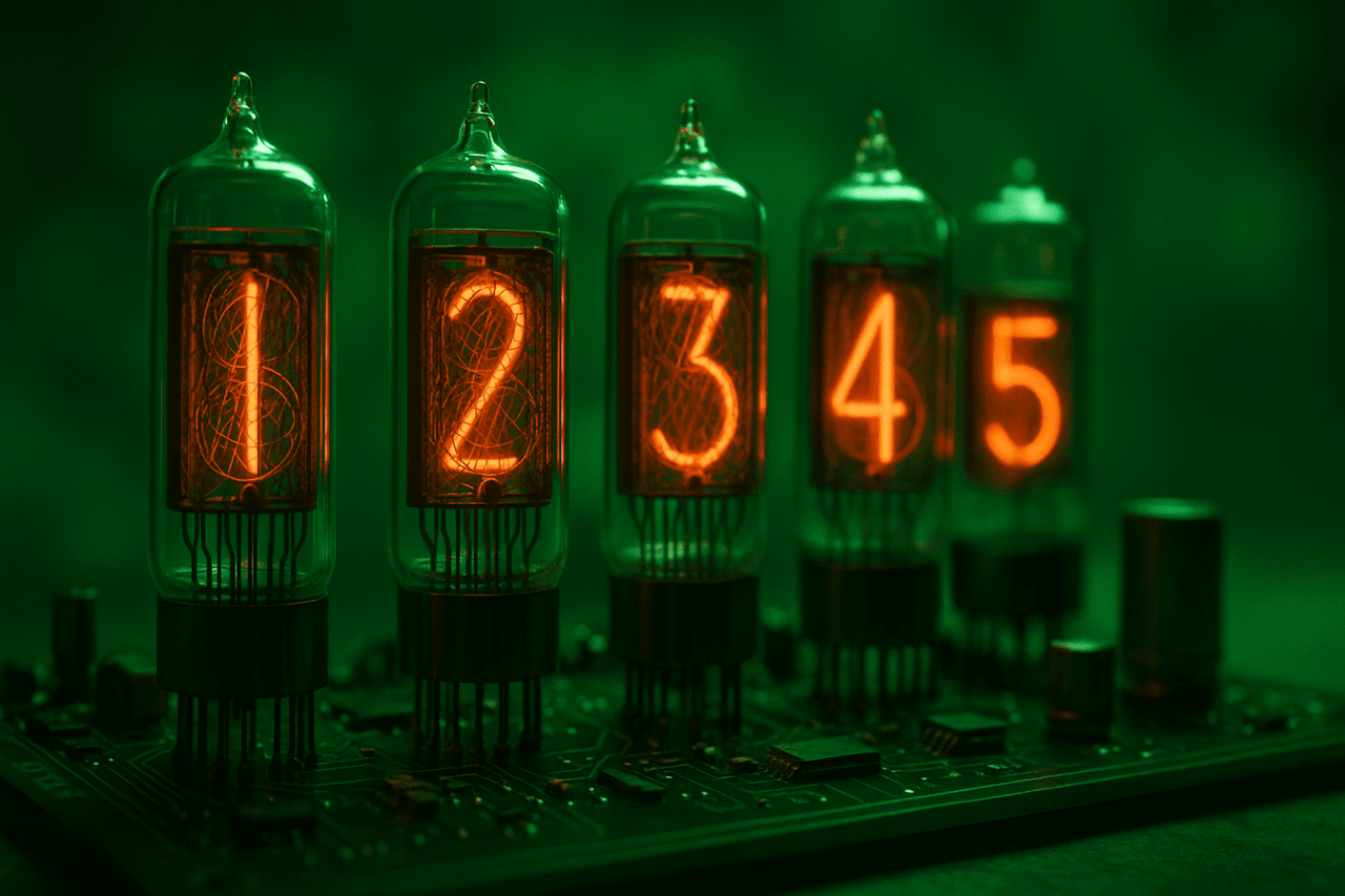
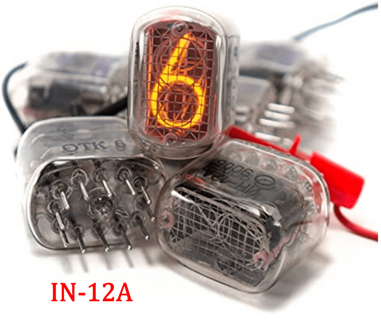
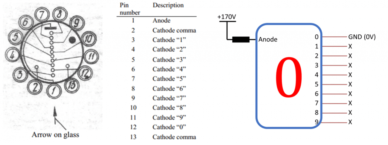
Gas-discharge indicators – IN-12A.
I would like to add a few more abilities.
Real-time clock (RTC) chip for more accurate timing and a small battery backup in case of power outage. (The problem with the old microwave clock).
Wi-Fi or GPS module for automatic time synchronization so you don’t have to set it manually.
PWM control for RGB LEDs to adjust brightness and get a wider color palette.
Self-resetting fuse (PTC) to protect against overcurrent in case of malfunction.
Linear gas-discharge indicator IN-9 as a second scale for a 4-digit clock. By the way, work has already begun and looks promising.
Independent connectors for indicators, as well as small adapter boards for different types. They would be connected to the main board via a simple pin connector. Then indicators of different models would be easily interchangeable. The adapter for IN-12A is ready.
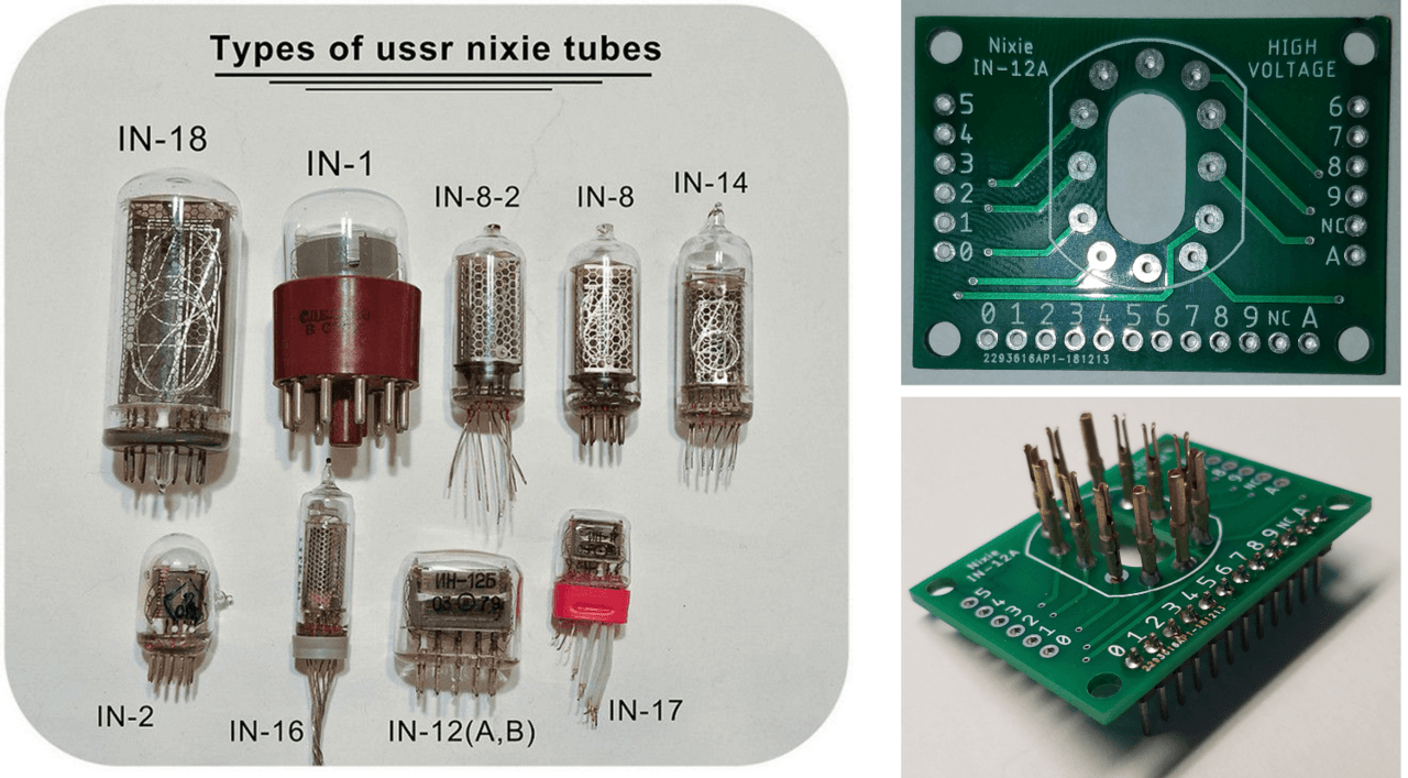
The purchased gas discharge indicators require a constant voltage of about 170 V to work.
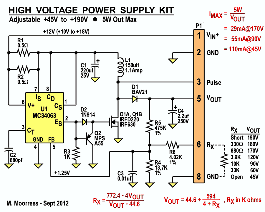
I found the work of Threeneuron (Michael Moorrees) – they seemed high-quality and well-documented. And I liked his approach. The high-voltage source required only 12 V DC at the input and produced a regulated voltage from 45 to 190 at the output – perfect. Instead of buying one of the ready-made kits (it seems that he still sold them at the time), I decided to copy his circuitry and implement it myself.
EAGLE was used to develop all the circuits and printed circuit boards.
However, my task required a few changes.
I had to add a 5-volt voltage stabilizer for the microcontroller controlling the logic on the indicator board. The selected stabilizer takes the available 12 V and outputs levels 5 to the output pin connectors.
I removed the “Pulse” output, since a higher voltage is not needed, and I wanted to reduce the number of contacts in the connector.
Instead of connecting an external potentiometer Rx, a 50 kΩ trimmer resistor was installed directly on the power supply board. And why not?
For ease of connection, I added alternating ground contacts to the output connector.
The circuit is quite simple, so I made the tracks only on the bottom layer of the board. That is why in one of the following photos the solder mask is only on one side.
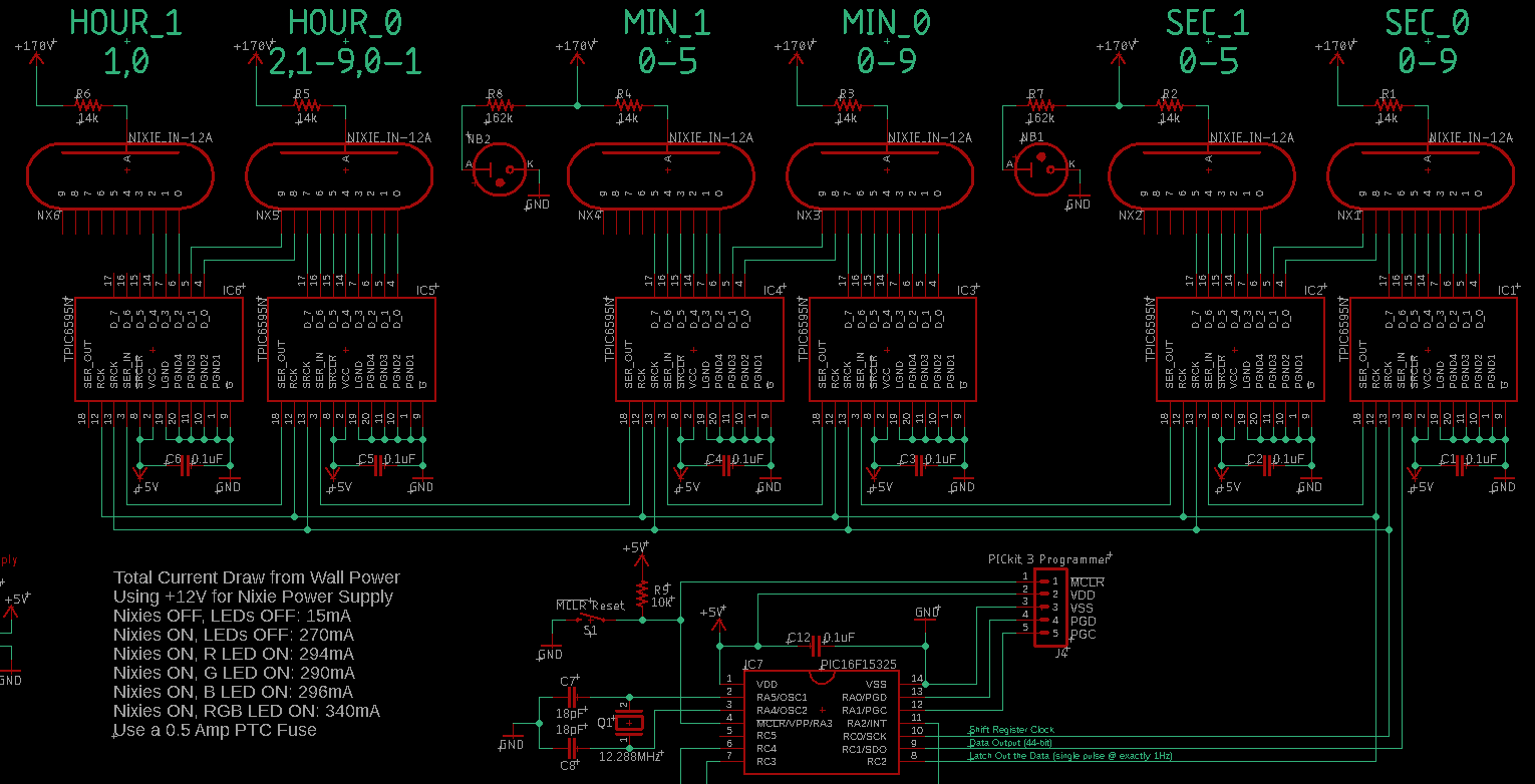
Selecting individual digits on gas discharge indicators is a fairly simple task. The anode is connected to a high voltage of +170 V through a current-limiting resistor. Then each of the 10 cathode terminals is shorted to ground (GND) to light up the corresponding digit. At any given time, only one of them should be lit.
Ideally, the remaining nine unused terminals should be disconnected and “hang in the air”, but this is unrealistic unless you want to put dozens of relays in the circuit. Bad idea! Instead, the nine terminals should be connected to a fairly high voltage, comparable to the anode. Then the breakdown voltage of the indicator will not be reached, and the digit will not light up.
Although gas discharge indicators require a high voltage, the total current consumption is small and does not cause problems.
The problem arises with high voltage and “turning off” the digits. Connecting or switching individual cathodes to ground is a trivial task for a simple microcontroller. But it cannot raise the voltage on the cathode high enough to “turn off” the digits. The voltage is much higher than what the microcontroller is capable of handling.
One solution is to control MOSFET switches connected to each cathode from the microcontroller. But then the circuit will be cluttered with a huge number of transistors. The logical solution is to use shift registers. The microcontroller controls the shift registers, and they already interact with high-voltage indicators. The registers act as an intermediary due to the large voltage difference.
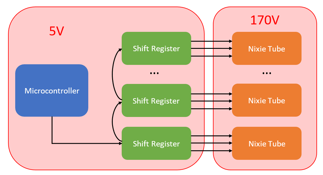
However, these must be “high voltage” shift registers, capable of holding the highest possible voltage on their outputs to prevent the indicators from lighting up. I copied the logic diagram from Dave Jones’ personal project, which uses an 8-bit power logic shift register TPIC6595 from Texas Instruments. The output stages (drain) have a voltage limit of 45, which is enough to effectively blank the indicator digits.
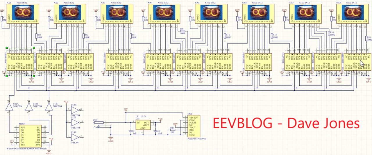
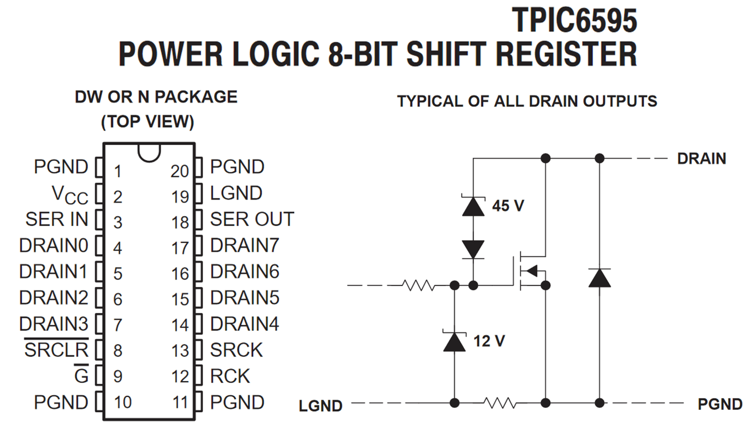
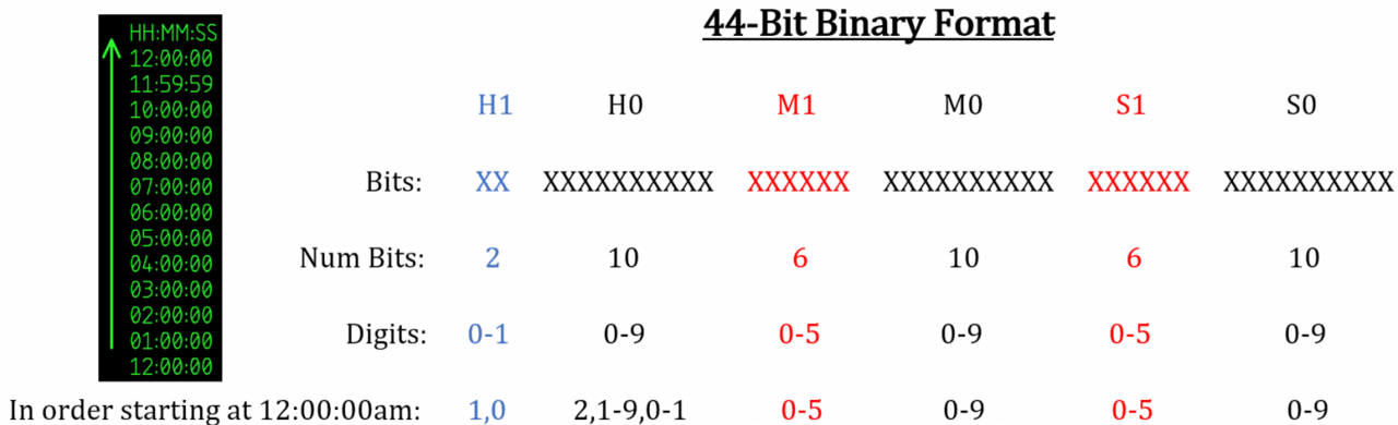
8-bit logic is used to control the switching of the indicator digits. Each individual bit output (DRAIN#) is connected to one indicator digit. Since each shift register chip has only eight outputs, and a 6-bit clock in the format H1 H0 : M1 M0 : C1 C0 is required, several registers must be connected in series. The SER IN and SER OUT pins of the register do allow such a combination, so that the logic can be extended from 8 bits to 16, 24, 32, and so on.
For the 12-hour format, the full representation of any allowed time requires 44 bits. In the format Ч1 Ч0 : М1 М0 : С1 С0, bits Ч0, М0, and С0 can represent all 10 digits from 0 to 9. Bits М1 and С1 only 6 digits from 0 to 5. Bit Ч1 only 2 digits, 0 or 1. Total: 3×10+4×6. The graph below explains this more clearly.
Although only 44 bits are needed for a 12-hour cycle, the final circuit included an additional bit connection in case someone wanted to convert them to a 24-hour cycle (45 bits).
The SER IN and SER OUT pins are connected in series to transfer 44 bits, but the RCK (lock pulse) and SRCK (shift register clock) pins must be common to all register chips. This is where the microcontroller comes in – it serves as the source of the 44-bit data, the clock for the registers, and the lock pulse.
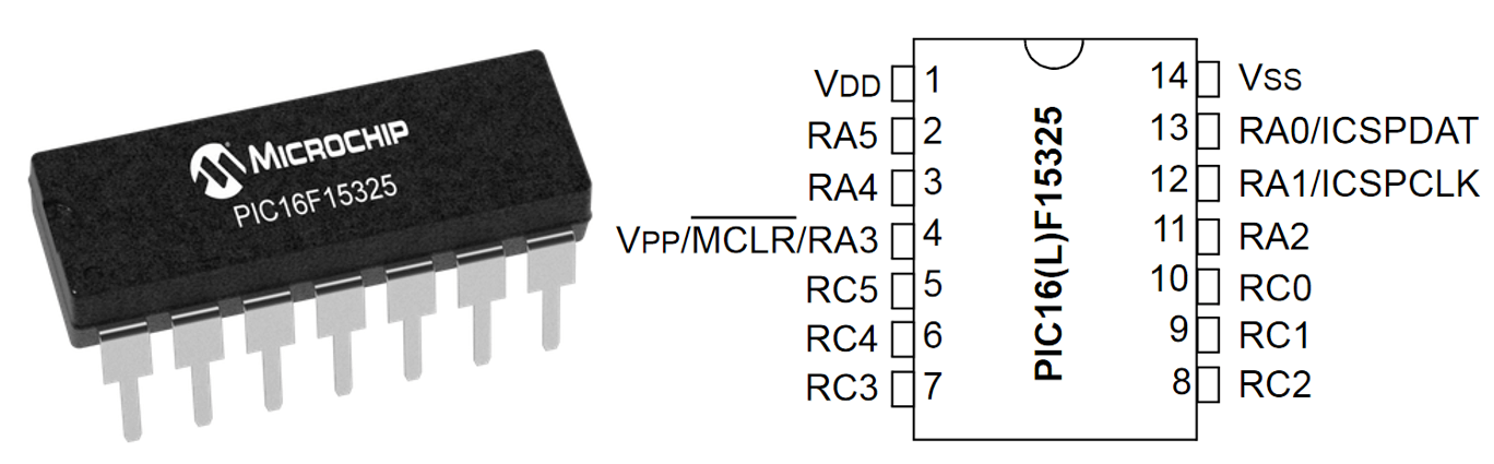
I chose a small 14-pin PIC16F15325 microcontroller from Microchip. I chose this PIC because of:
compact housing;
availability of serial interfaces, pins for external interrupts and the PPS (Peripheral Pin Select) function, which provides flexibility in assigning pin functions.
A large 40-pin PIC would have been overkill, leaving a lot of unused pins. As a result, only one pin was unused in the final circuit.
The PIC is wired with standard wiring: a reset button (MCLR), a connector for the PICkit 3 programmer, and an external crystal to clock the internal oscillator. I chose a 12.288 MHz crystal because its frequency is easy to divide to the exact second pulses of my clock frequency.
The link to the C source file is at the top of the page. I think it’s pretty well commented. All the details are there. In the PIC code, time is stored as elapsed seconds in decimal format: 43,200 seconds is 12 hours. Every second an interrupt is fired, after which two steps occur.
The number of seconds is converted into six integer variables – for Ч1 Ч0 : М1 М0 : С1 С0.
The individual time digits are converted into a 44-bit message to be sent to the shift registers. The 44 bits are sent in 8-bit chunks, starting with Ч1 and ending with С0.
// КРОК 1
// Розбиваємо змінну myTime (загальне число секунд) на години, хвилини, секунди,
// а потім кожну з них — на окремі цифри
if (myTime >= 43200) // 12 годин — це 43 200 секунд
    myTime = 0;      // скидаємо лічильник годин

// Кодування ГГ:ХХ:СС (12-годинний формат, без AM/PM)
// Г1 Г0 : Х1 Х0 : С1 С0
secs = myTime % 60;
s1 = secs / 10;
s0 = secs % 10;

mins = (myTime / 60) % 60;
m1 = mins / 10;
m0 = mins % 10;

hours = myTime / 3600;
if (hours == 0) // особливий випадок
    hours = 12;

h1 = hours / 10;
h0 = hours % 10;
// КРОК 2
// Кодуємо/форматуємо змінні вище в «незвичний» двійковий вигляд для зсувних регістрів
// Для кожного окремого двійкового числа лише один біт може бути у стані HIGH (1)
// 44-бітний двійковий формат для зсувних регістрів (Г1Г0:Х1Х0:С1С0):
// (старший біт) XX XXXXXXXXXX XXXXXX XXXXXXXXXX XXXXXX XXXXXXXXXX (молодший біт)

// Необхідно відправляти 8-бітними порціями
// Потрібно послідовно зсунути це 44-бітне число, по 8 біт за раз
// Відправлення починається зі сторони старшого біта (години)

// кодуємо і відправляємо дані послідовно
// (але ще не відображаємо; це відбувається в обробнику переривання таймера,
// який викликає latchoutData() і подає імпульс на вивід RCK)

// 0-й біт shiftReg підключений до цифри «0» індикатора, і так далі за логікою...
bin_hour1 = (unsigned int)pow(2,h1);
bin_hour0 = (unsigned int)pow(2,h0);
bin_min1  = (unsigned int)pow(2,m1);
bin_min0  = (unsigned int)pow(2,m0);
bin_sec1  = (unsigned int)pow(2,s1);
bin_sec0  = (unsigned int)pow(2,s0);

// для надійності, можливо, варто обгорнути цей код з вимкненням усіх переривань
SSP1BUF = 0b00001111 & (((bin_hour1<<2)&0b1100) | ((bin_hour0>>8)&0b11));
while(SSP1STATbits.BF == 0);
SSP1BUF = bin_hour0;
while(SSP1STATbits.BF == 0);
SSP1BUF = ((bin_min1<<2)&0b11111100) | ((bin_min0>>8)&0b11);
while(SSP1STATbits.BF == 0);
SSP1BUF = bin_min0;
while(SSP1STATbits.BF == 0);
SSP1BUF = ((bin_sec1<<2)&0b11111100) | ((bin_sec0>>8)&0b11);
while(SSP1STATbits.BF == 0);
SSP1BUF = bin_sec0;
while(SSP1STATbits.BF == 0);
The first part of the history of the Nixie clock shows how a real engineering project is born from the fascination with the beauty of gas-discharge indicators. The author went from first impressions and information search to the formation of clear requirements: the use of a PIC microcontroller instead of complex platforms, a separate high-voltage power supply unit, six indicators in a 12-hour format, RGB LED backlighting and control via an encoder. An important stage was also the design of the logic part using shift registers to control the cathodes.
Thus, at the output we received not just the idea of “making a beautiful clock”, but a well-thought-out technical concept with real circuitry, which opens the door to the next step – practical implementation and assembly.