27.09.2025
10 min
724

The second part of the Nixie clock project is dedicated to practical implementation. It describes how to connect a PIC16 to shift registers, encode the time in 44 bits and correctly transmit it to the indicators. The operation of RGB LEDs, switches and a rotary encoder for setting the time is considered. Prototyping, layout, creating printed circuit boards in EAGLE and assembling the case from an old wooden box are shown step by step. This is a detailed guide for those who want to assemble a stylish Nixie clock themselves.
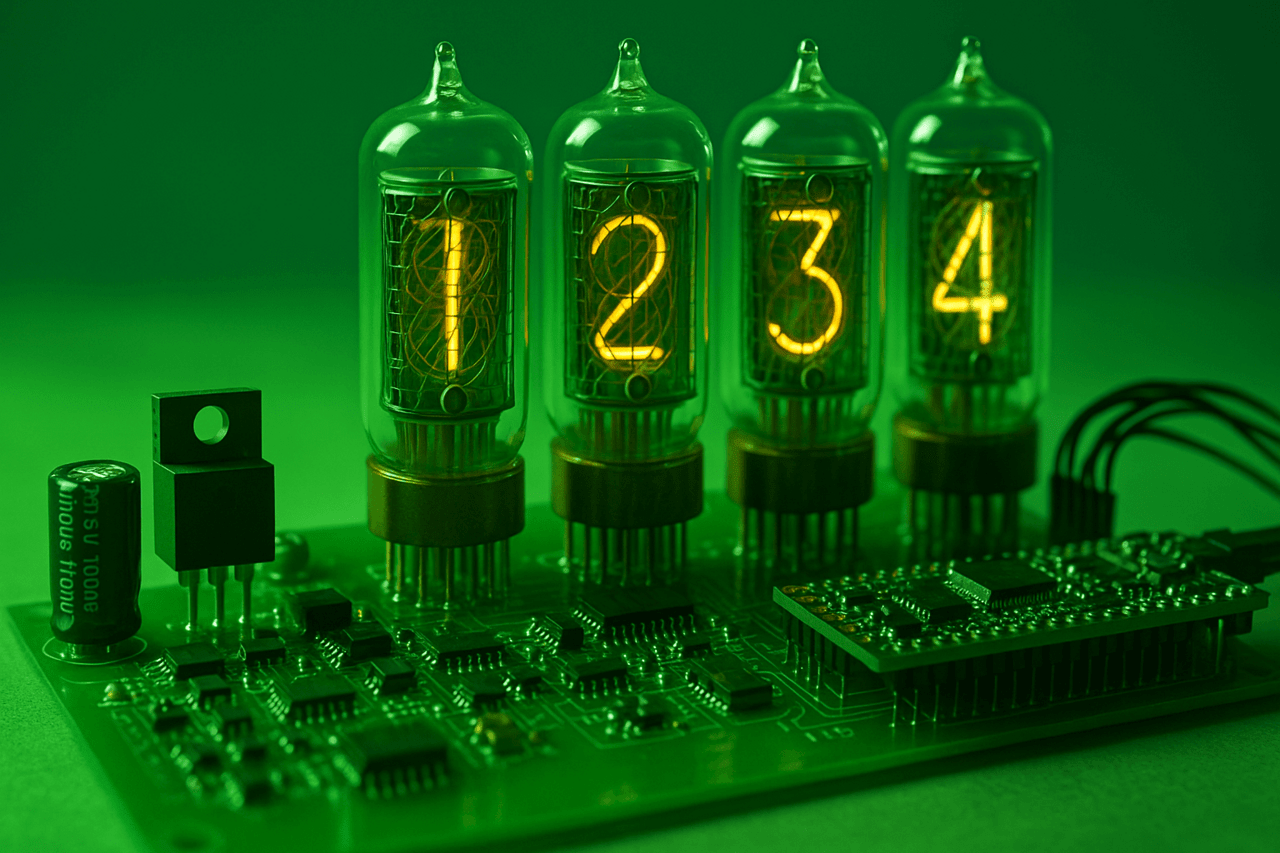
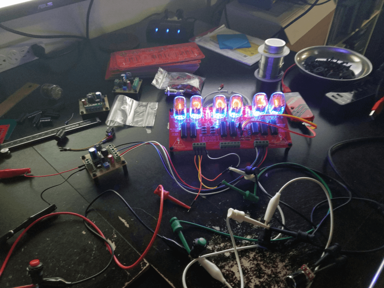
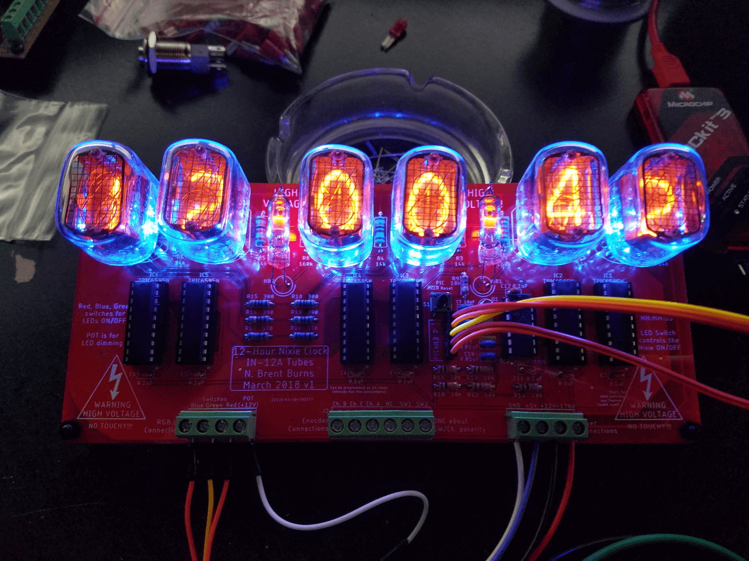
Six Cree CLY6D-FKC-CK1N1D1BB7D3D3 SMD RGB LEDs were installed under each LED to add color. So pretty! Since each LED is in a glass bulb, the light from the LEDs passes through it very well.
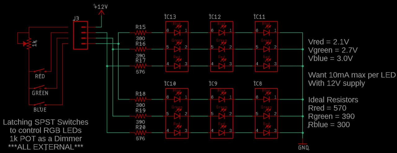
Each LED contains three independent crystals – red, green, and blue. They are controlled by latching pushbutton switches. In the future, they may be coordinated by a microcontroller with PWM brightness control.
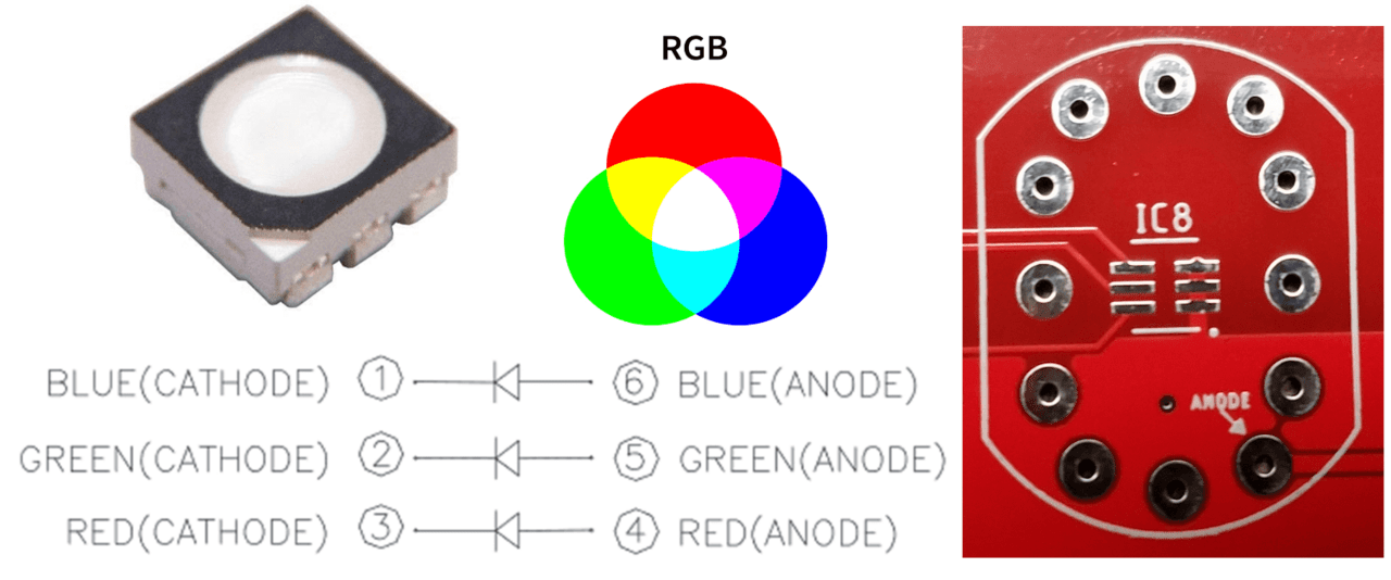
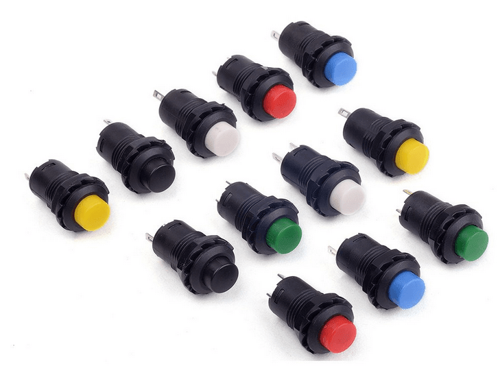
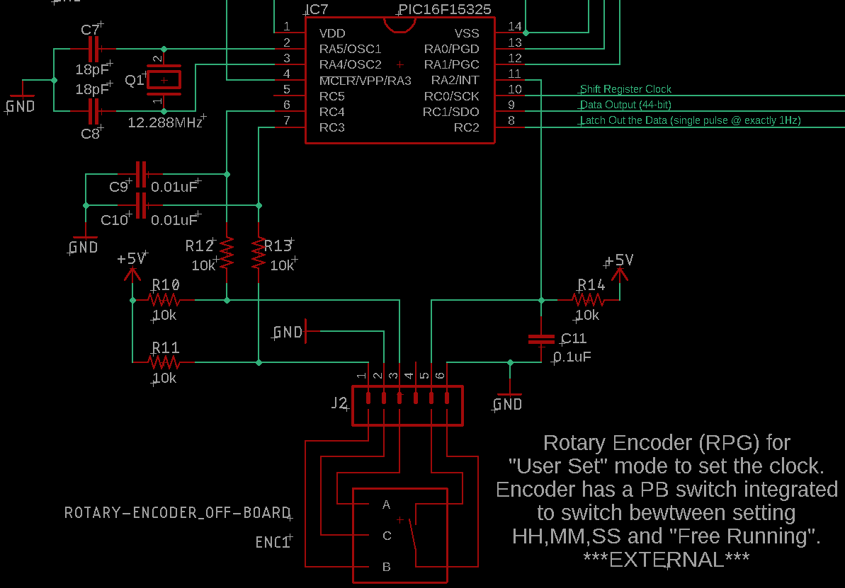
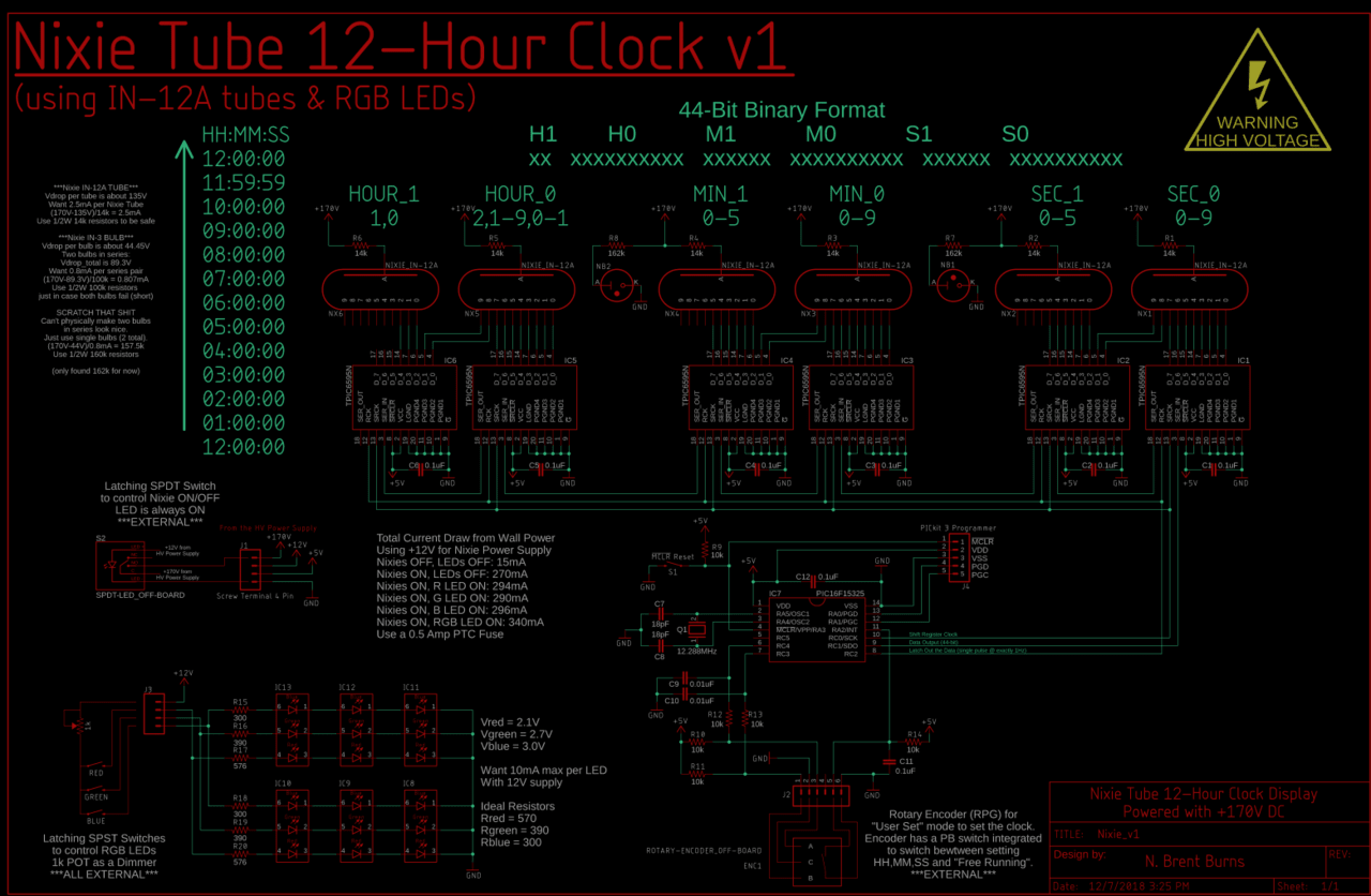
The three colors for all six RGB LEDs are controlled by self-locking pushbutton switches of the corresponding color – red, green and blue. The variable resistor shown in the diagram below did not make it into the final version. It did not bring much benefit. You can choose a combination of red, green and blue to mix them and get several other colors of the spectrum.
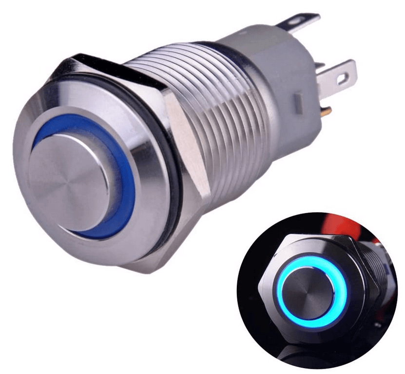
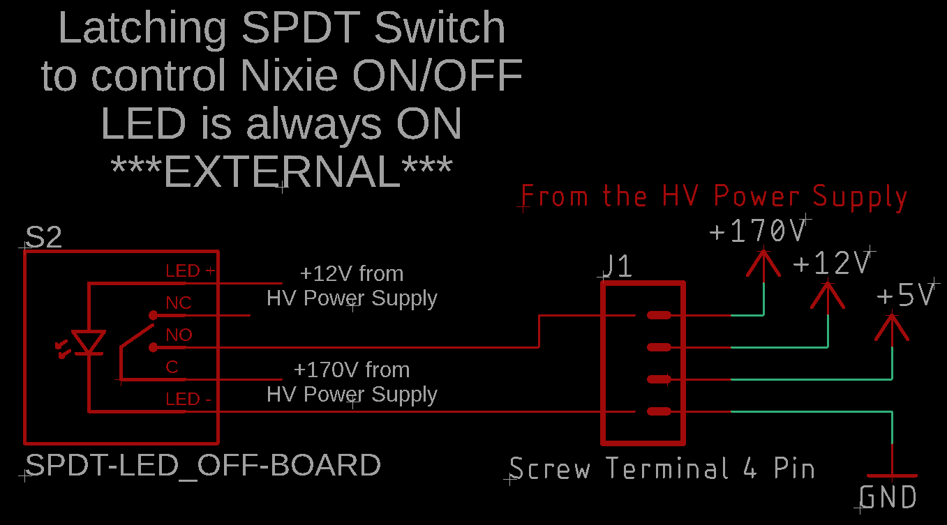
A larger latching push-button switch was added to control the glow of the gas-discharge indicators. It does not control the entire circuit power supply (12 V), but only the 170 V voltage supplied to the indicator anodes. The logic part of the circuit remains energized and continues the countdown – only the indicators themselves are turned off. The LED ring of the button shown in the diagram below was not used.
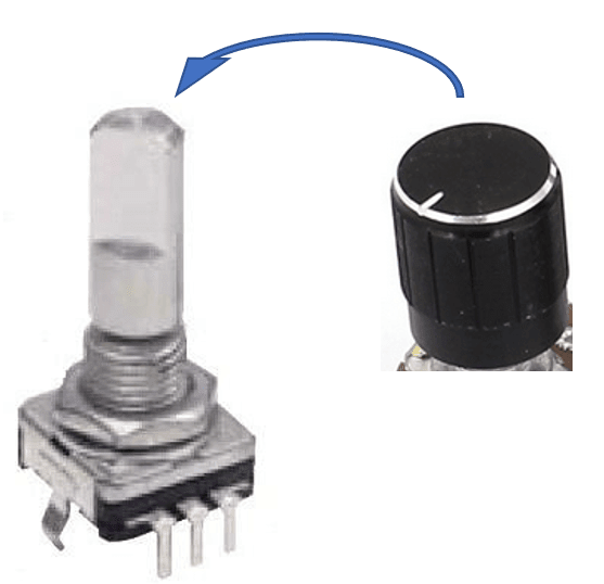
For manual setting and adjustment of the time, a rotary encoder (Bourns PEC11R-4015F-S0024) with a removable handle taken from the potentiometer kit is used. The encoder has two functions: a non-detenting button and continuous rotation in both directions. Pressing the encoder button sends an external interrupt to the PIC microcontroller, allowing the user to manually set the exact time in a few steps:
The clock operates in normal freewheel mode.
Press the encoder button to enter the setting mode, rotate the encoder to set the hour.
Press the button again – rotate to set the minutes.
Press again – rotate to set the seconds.
The last press – return to freewheel mode.
The diagram below shows a circuit for suppressing the chatter of the button and encoder contacts, consisting of capacitors and pull-up/pull-down resistors. It has significantly improved the accuracy of operation.
Initially, a high-voltage source circuit was assembled on a breadboard, and it worked well.
Observation on the oscilloscope showed a small ripple at the high voltage output – nothing serious, just a few volts. This is a trifle against the background of +170 V, but for some reason I wanted to smooth it out with a high-voltage capacitor. Yes, it weakened the ripple a little, but did not completely remove it.
It was decided to abandon this trick and remove the capacitor, forgetting – idiot! – that it was fully charged to +170 V. I touched it with my hand – and it shook decently.
Attention! Always remember that capacitors must be discharged through a resistor of medium value!
I drew the circuit and printed circuit board in EAGLE. I placed the order with JLCPCB. I soldered it when all the parts arrived. The board worked just as well as the layout. I used the finished high-voltage source board for prototyping and layout of the main clock circuit.
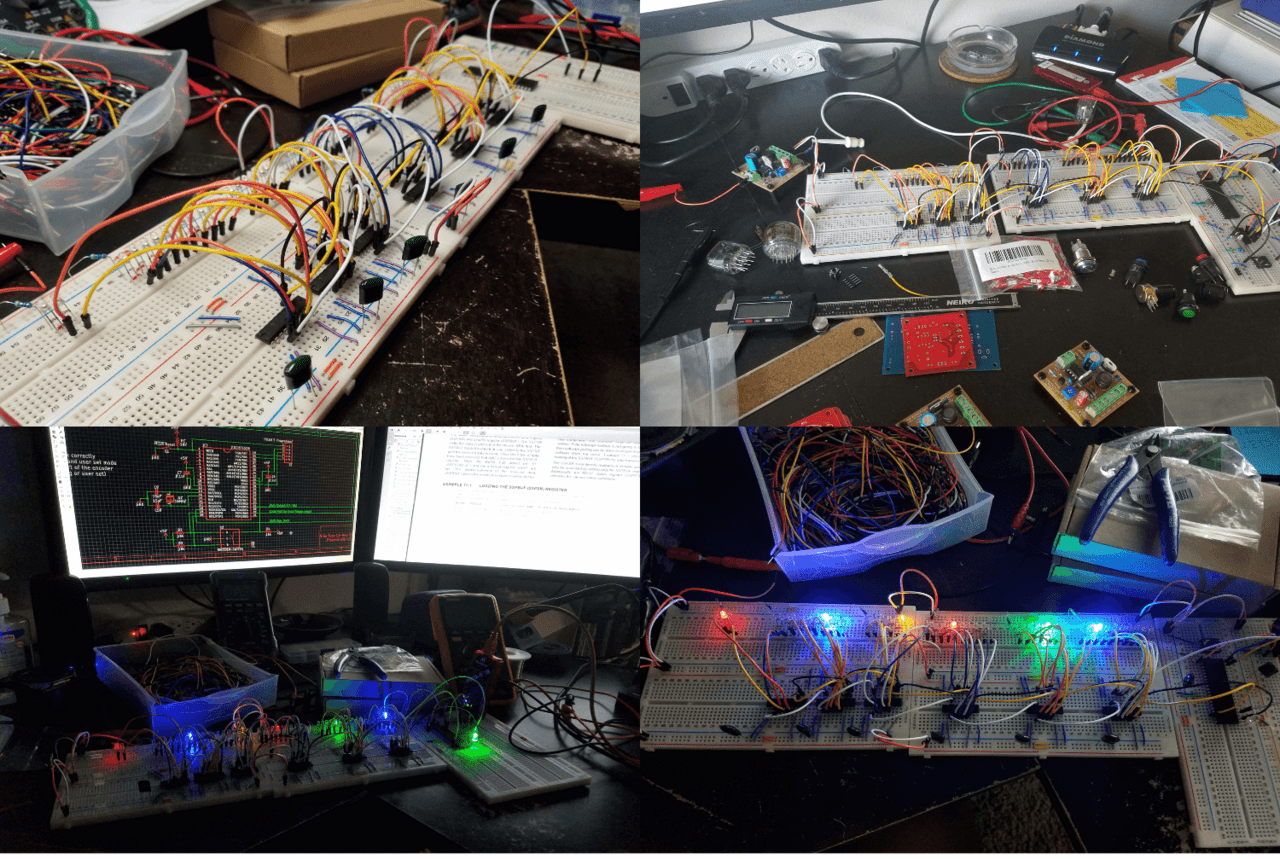
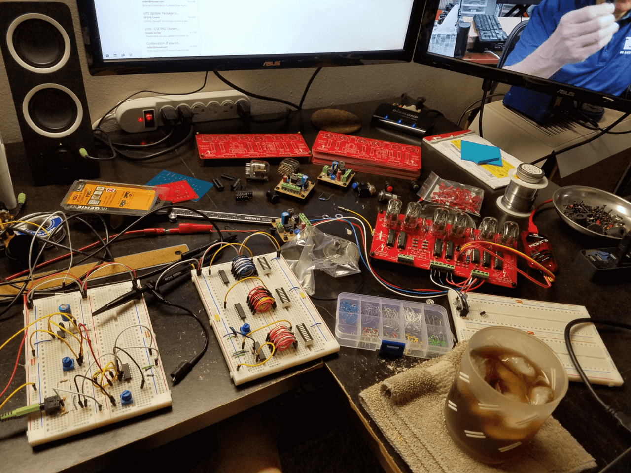
When I had a working circuit and a schematic diagram for the main clock board almost ready, I started prototyping individual project nodes on an old breadboard (one of my favorite things to do).
Connecting the shift registers, PIC, buttons, and encoder turned out to be quite simple. The difficulty was programming the PIC and correctly converting the “digital time” to 44-bit binary data for the shift registers.
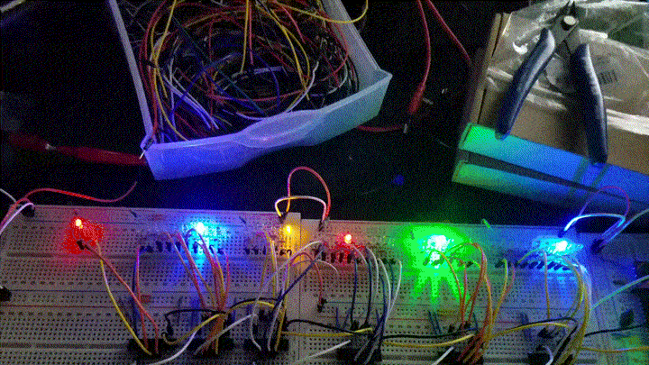
I did not use gas-discharge indicators to write and debug the code. Instead, I used regular LEDs to simulate digits, and as a result, I debugged the code in C to work correctly with the shift registers.
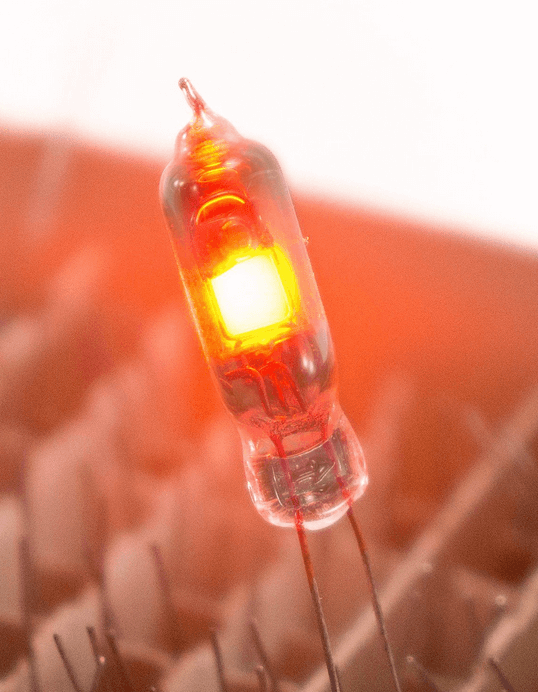
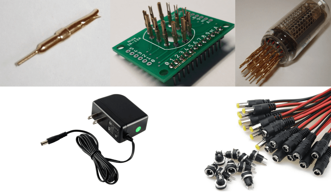
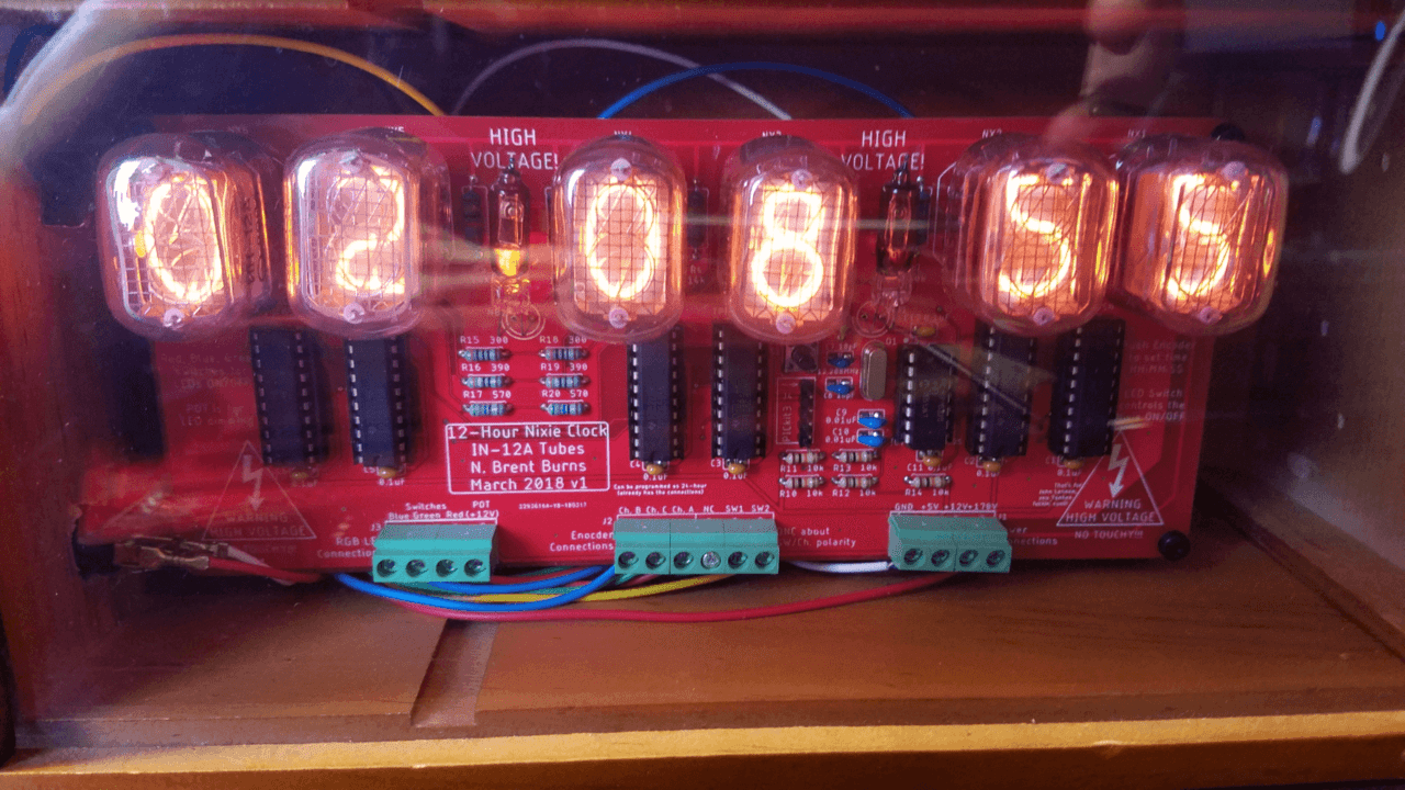
EAGLE was useful for creating the circuit and custom components that were not in the libraries. Links to the files themselves are in the first part. You can see in the circuit that two other gas discharge indicators have been added as separators between the discharges – these are IN-3 neon bulbs.
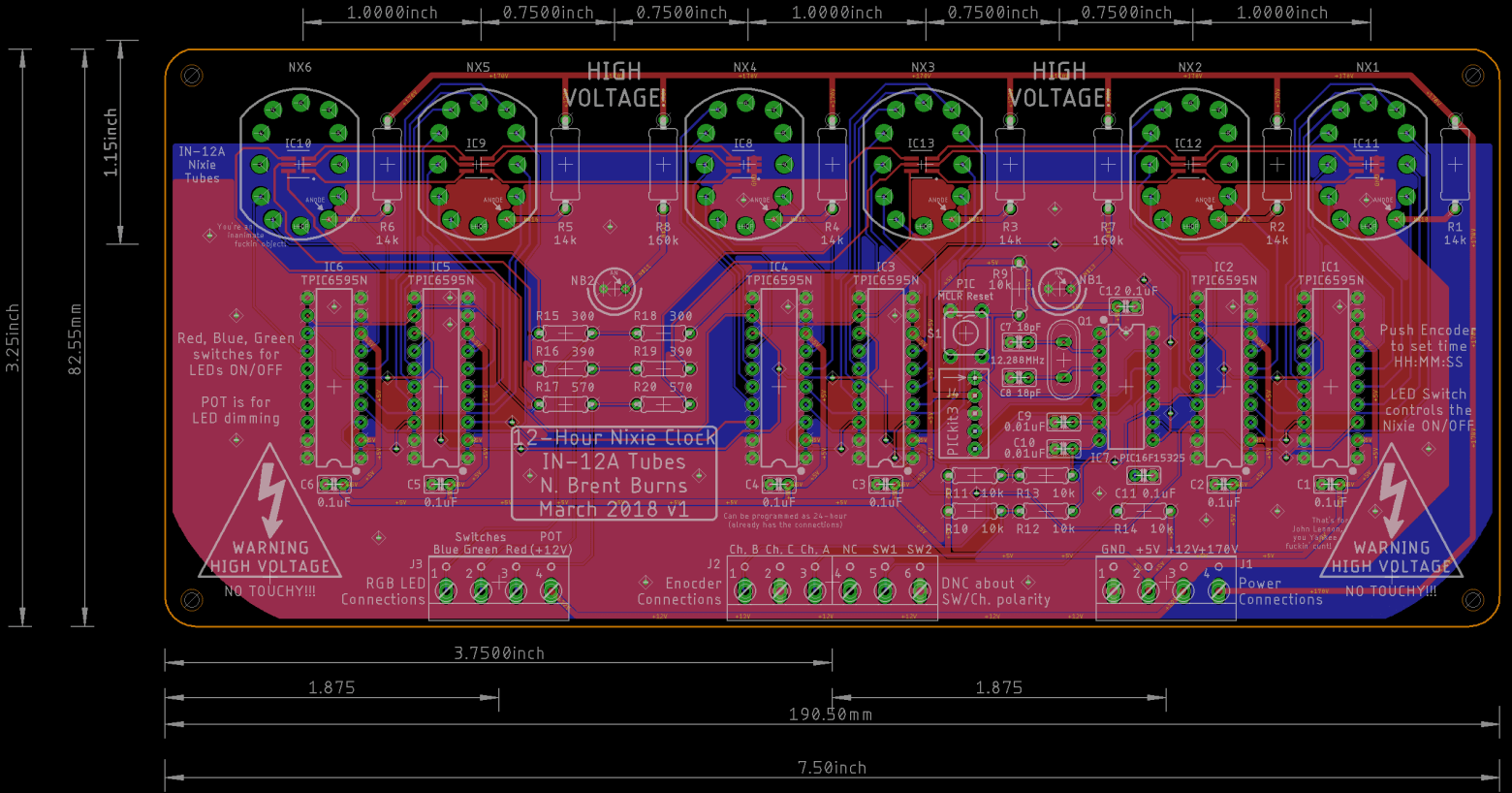
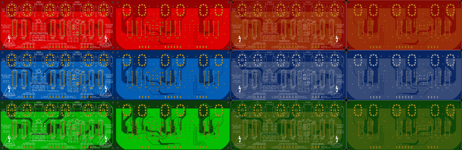
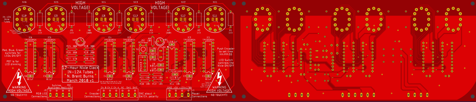
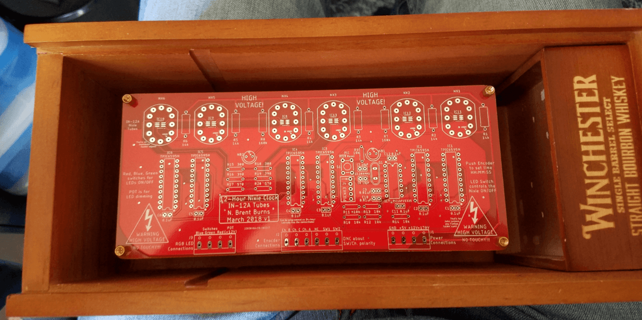
The PCBs were also created in EAGLE. The main board of the clock is two-layer (top and bottom layers with ground polygons) with rounded corners (why not).
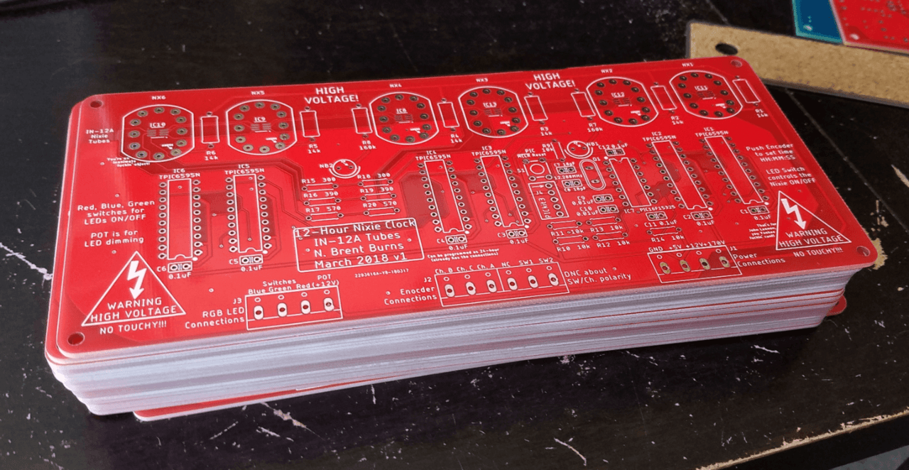
I ordered the physical boards from China from JLCPCB. They have low prices and high quality for simple home DIY projects. The delivery is also very fast. I highly recommend them. I chose the red solder mask and didn’t notice my typo “Enocder” until the boards arrived.
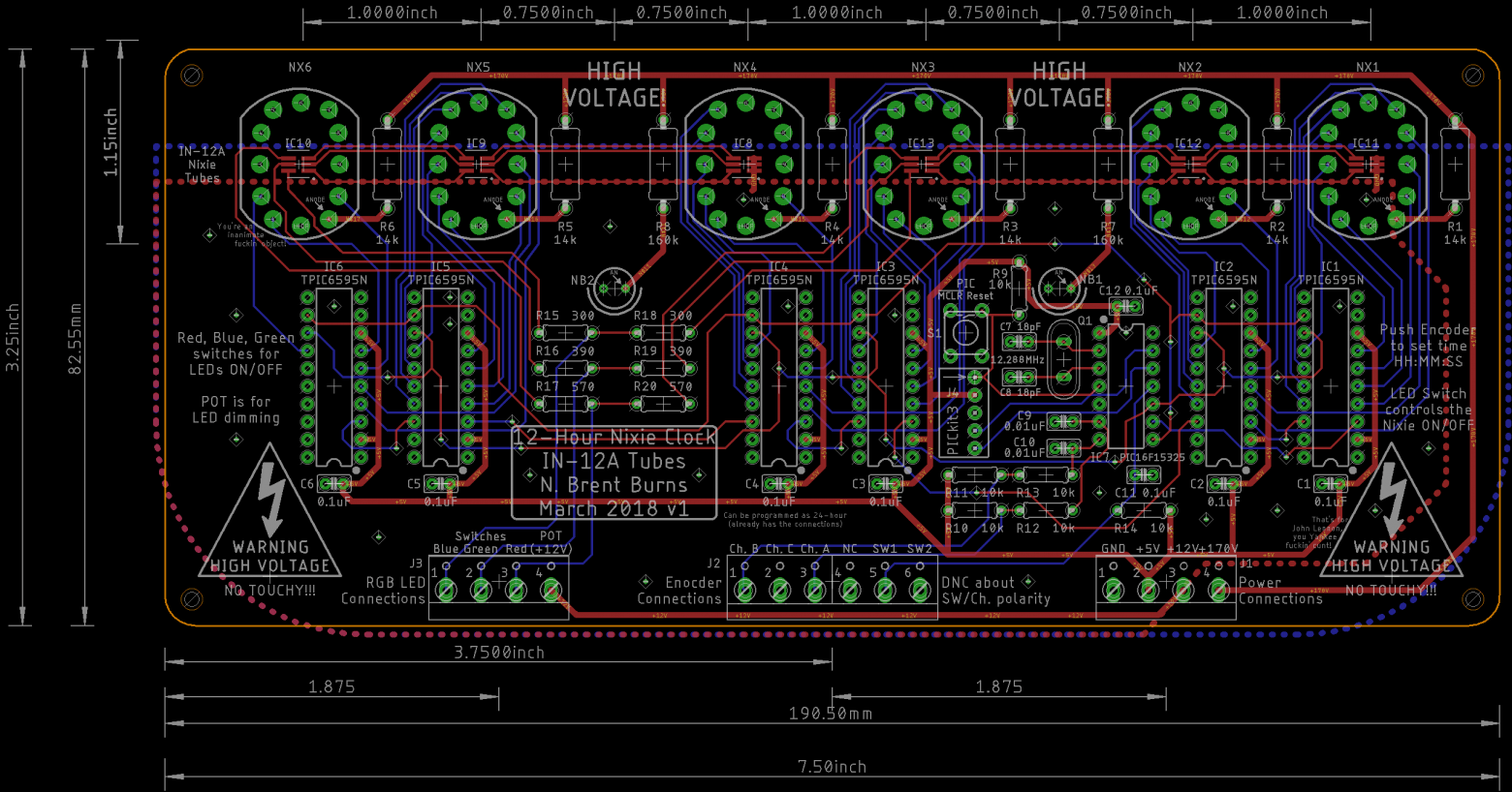
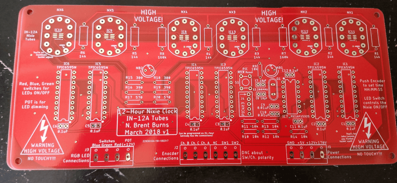
Soldering all the components didn’t take long. The most difficult part was manually soldering the small SMD RGB LEDs. A few pieces didn’t survive the procedure. I didn’t integrate the indicators directly into the board. Instead, I soldered separate panels and Nixie connectors, which will allow me to easily replace faulty indicators in the future. I used screw terminals for all wire connections between the two boards and external components. I also installed all the chips in DIP panels, and didn’t solder them directly.
The entire circuit is powered by a regular AC/DC adapter with a 12V DC output. An adapter with a maximum current of 2A was selected after previously measuring the consumption of the assembled circuit. The connection is made via a “mother” type power connector with pins.
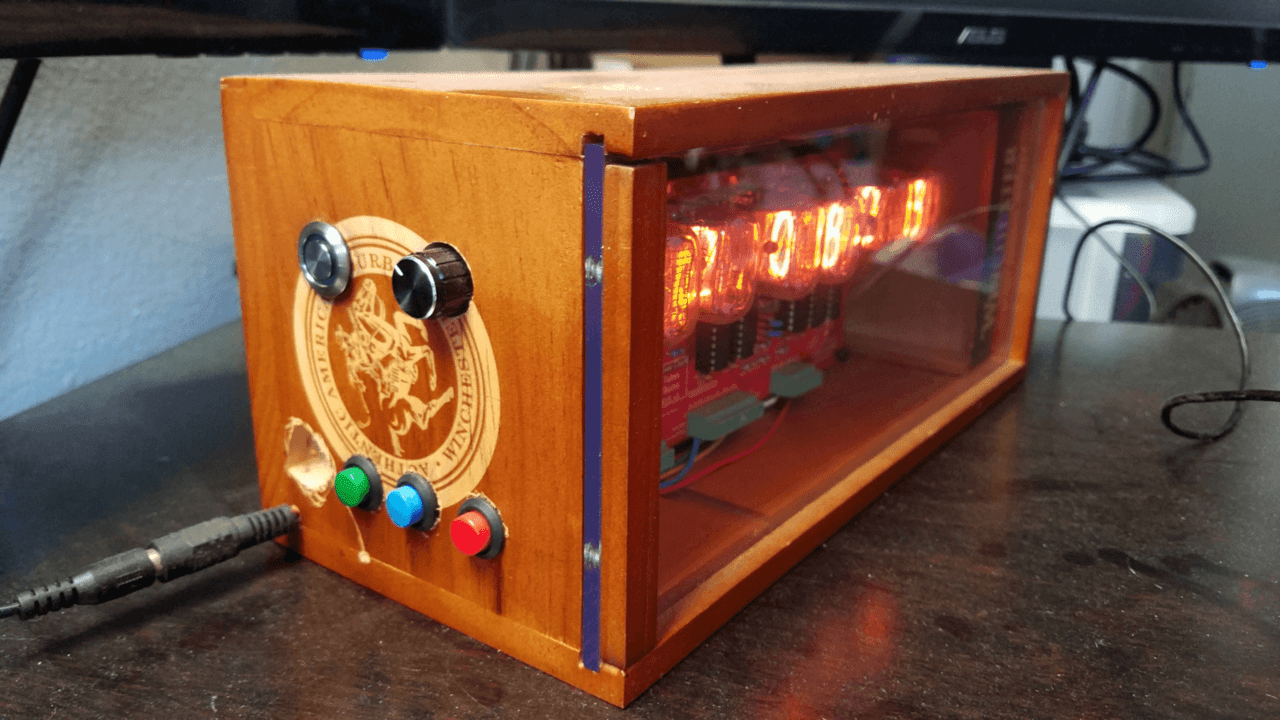
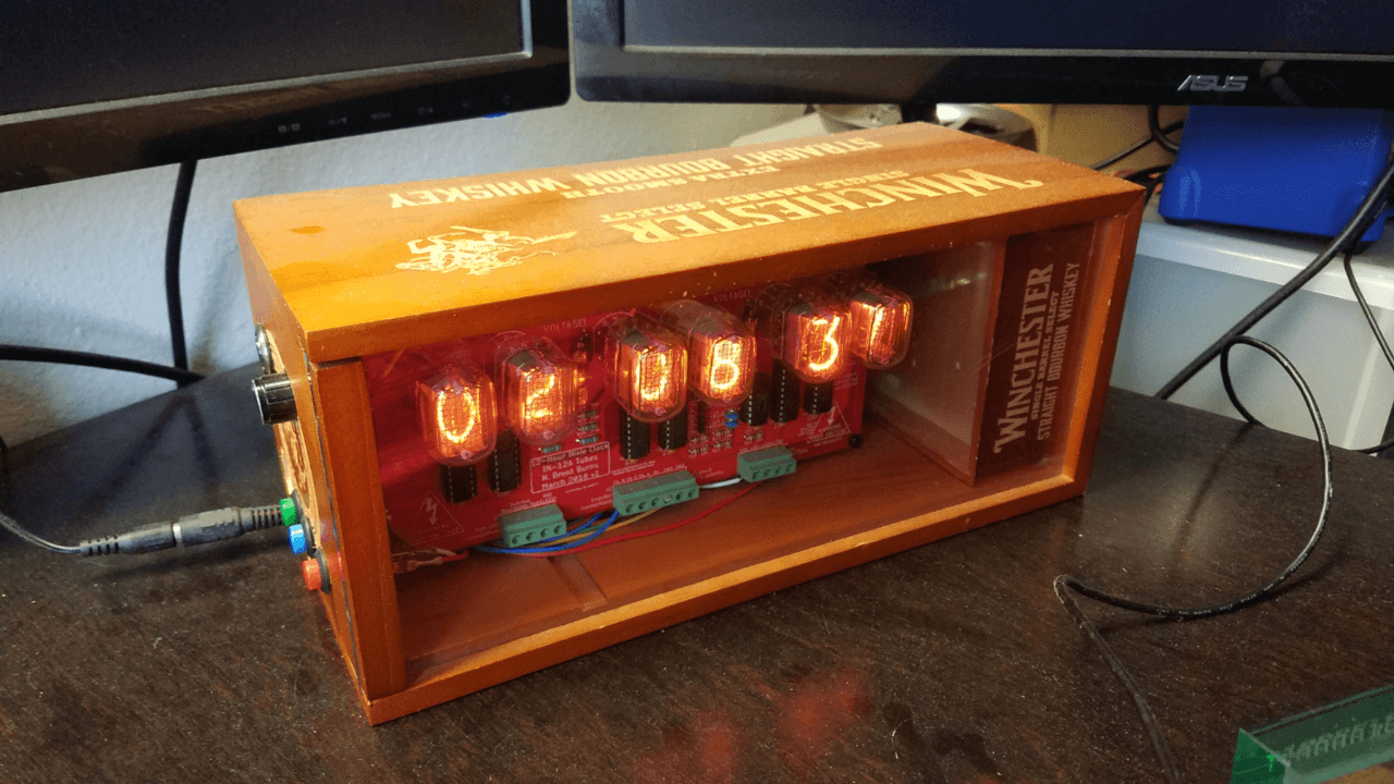
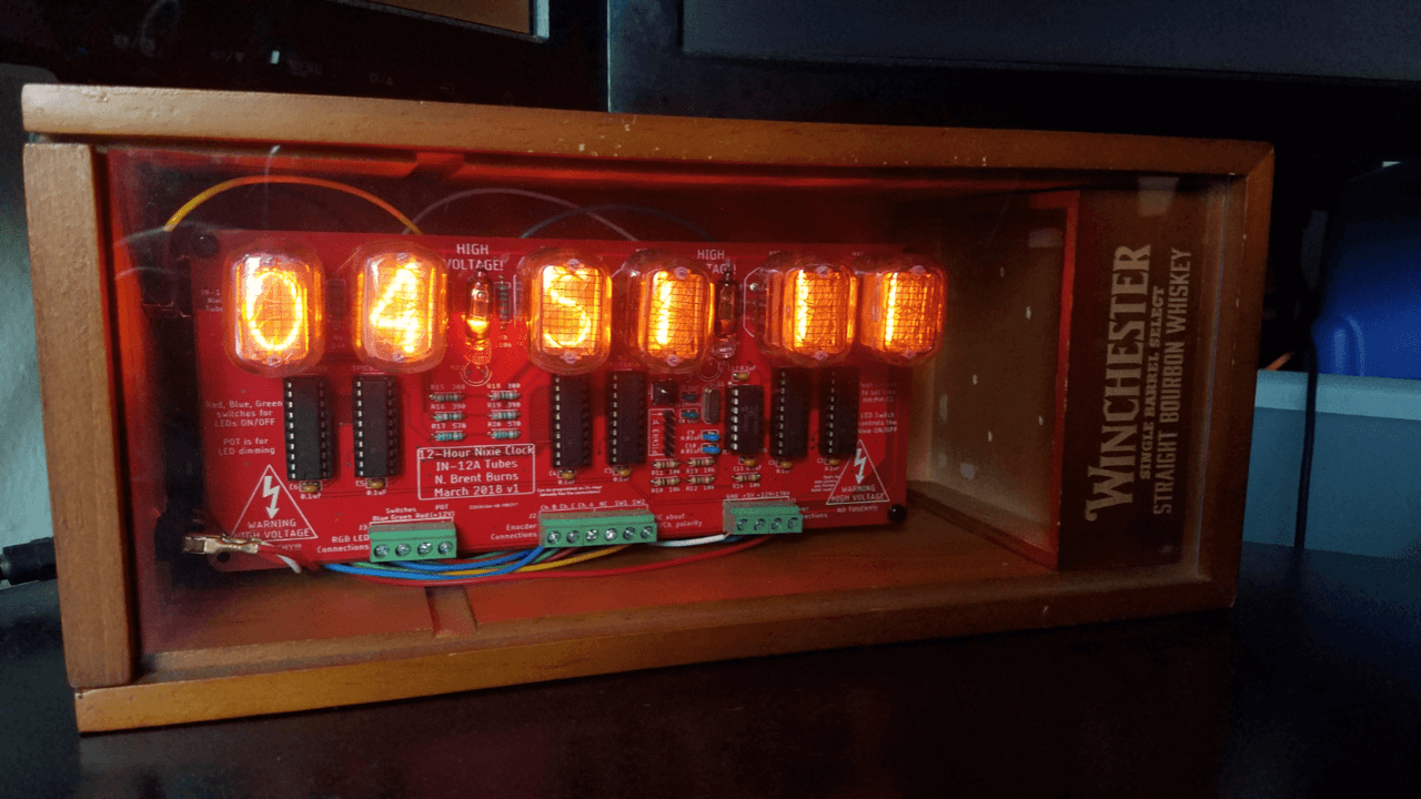
An old wooden bourbon box with a sliding Plexiglas lid was suitable as the clock case. I chose it at an early stage to determine the final size of the board. In the left wall of the wooden box, I drilled holes for the LED switches, indicator switch, rotary encoder and power cable.
The high-voltage power supply board is mounted behind the main one – near the back wall of the box and hidden from view. The main clock board is also attached to the back wall, but on much longer posts to raise it above the power supply board.
In conclusion, I would like to say that we are absolutely delighted with this project! It has become a great way to distract from graduate school and has helped to deepen our knowledge in various fields.
The work on the clock was completed in March 2018, and to this day (December 2020) they work perfectly. Although the accuracy of the second interval is not ideal and the error accumulates over time, they have to be manually adjusted about once every six months. I hope to increase the accuracy in the next version by adding a real-time clock chip.
Thank you for your attention! And now – the juiciest photos of the finished product.
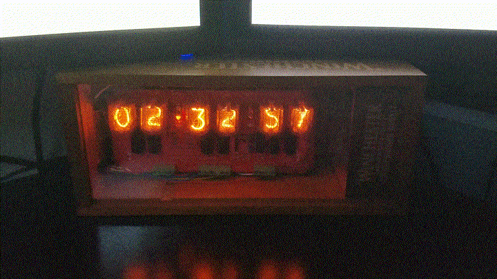
This part shows how the idea of a Nixie clock gradually turned into a full-fledged finished device. The author went through all the key stages: from experiments with RGB backlighting, buttons and an encoder to prototyping, creating printed circuit boards in EAGLE and assembling the case. Both technical discoveries (for example, the correct suppression of contact chatter) and personal experience became important, in particular working with high voltage, which added practical understanding and caution.
The final result is a clock that combines the old aesthetics of gas-discharge indicators with modern electronics, modularity and manual adjustment. The project turned out to be not only beautiful and functional, but also a valuable learning experience, which confirmed that even complex tasks can be implemented step by step if you combine interest, patience and attention to detail.