
15.12.2023
5 min
3158

Explore the world of TCP/IP with our article that delves into the theory and practice behind these basic elements of the Internet. Understand the structure, functionality, and application of TCP/IP in networks, which is critical for professionals and enthusiasts alike. The article breaks down complex concepts into easy-to-understand terms, providing an understanding of how the Internet works at its core. Ideal for IT professionals, students and anyone interested in the workings of network communications. When we think about computer networks, we often delve into the physical basis and structure of the data transmitted over the network, and when we think about network programming, the main focus is on Internet connectors.
However, as you learn and explore, you may want to do more, such as experimenting with network protocol suites. Many network protocols are implemented in the operating system kernel, which can be a difficult task because any change requires the skill of writing drivers for the operating system. However, specialized libraries allow working with low-level protocols from user space. While writing this article, I wrote a small program that provides a starting point for understanding computer networks and the TCP/IP family of protocols. With the help of this program, you can experiment and gain further knowledge. This program is simple and straightforward and will make it easier for you to learn the content of this article. After all, the joy of the first victory gives the motivation necessary to devote more time to studying the topic. This article covers the most important concepts that every computer network programmer should know.
A computer network is a collection of computing devices that interact and share resources. The concept of a network is similar to the concept of a graph. The network also consists of a certain number of nodes and links. The difference between a network and a graph is that nodes are meaningful objects, in this case computing devices, and links are connections between these devices. In Russian literature, computer networks are sometimes called computing networks.
Depending on the coverage of the territory, computer networks are:
Personal – Personal Area Network (PAN).
Local – Local Area Network (LAN).
Urban – Metropolitan Area Network (MAN).
Global – Wide Area Network (WAN).
Various sensors connected to a smartphone form a PAN network. The computer network of devices connected to your home router is a LAN network, the network of subscribers of the provider in the city is the MAN network, and the entire Internet provided to you by the provider is the WAN network.
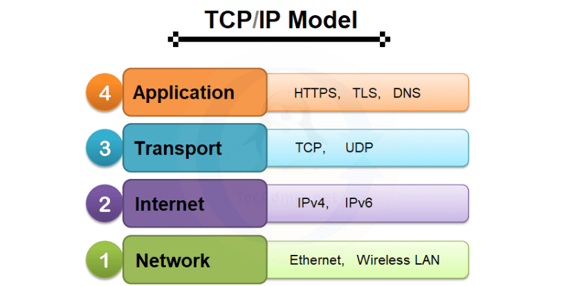
A network model is a conceptual framework that standardizes network interaction. It includes basic terminology, as well as the purpose and functions of network components. A network model divides network components and their functions into layers. Each layer of the network model has a specific purpose and function.
Currently, two network models are most common. It is a seven-layer OSI model and a four-layer TCP/IP model. Let’s give a diagram of the models and how they relate to each other.
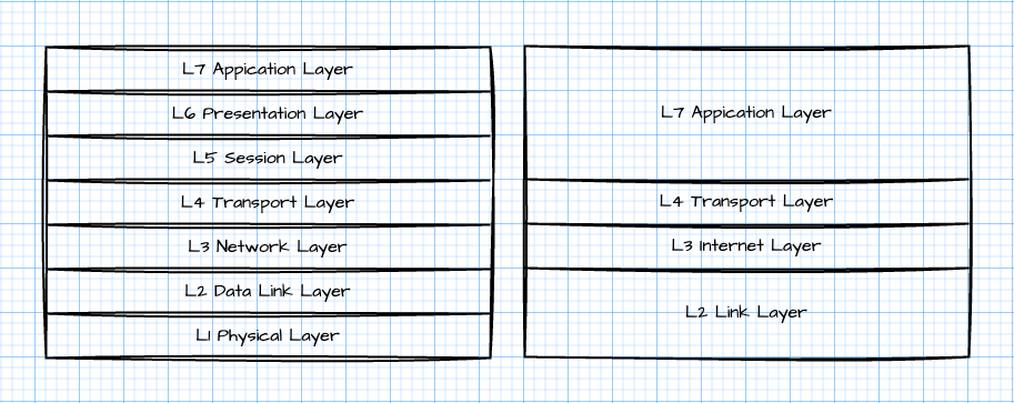
In most cases, you will be dealing with the TCP/IP network model, but historically, layer numbers have been used from the OSI network model. For example, when the term Layer 2 or L2 is encountered, it means layer 1 (channel layer) of the TCP/IP model.
Layering allows each layer’s technologies to evolve independently of the others. For example, thanks to the widespread introduction of fiber optics, the speed of the Internet increased tens or even hundreds of times, and the Internet was based on the IP protocol and continues to be based on it.
Most current Internet standards and TCP/IP protocols are governed by Request For Comments (RFC) documents. Textbooks on computer networks aim to explain the TCP/IP model, but for a precise interpretation of the concepts, it is better to refer to the RFC.
The TCP/IP network model is discussed in detail in RFC 1122 (Requirements for Internet Hosts – Communication Layers) and RFC-1123 (Requirements for Internet Hosts – Application and Support). The model is explained and extended by other RFCs, but to understand the basics.
host (host);
message;
IP datagram;
package;
frame;
IP address;
MAC address;
TCP segment;
UDP datagram;
MTU.
An IP network is a set of interconnected hosts. Computers are connected directly or indirectly using relay devices (routers and switches). Hosts use interfaces to receive messages from the network and send messages to the network. Physical interfaces send and receive frames, logical interfaces send and receive IP packets.
A physical interface is identified by a MAC address, and a logical interface is identified by an IP address. Messages are either UDP datagrams or TCP segments. The message contains a header and useful data; to send a message to an IP network, it is enclosed in an IP datagram; if the size of the IP datagram exceeds the MTU, it is fragmented and several IP packets are generated, otherwise – one for the entire IP datagram.
Only one IP packet is generated. IP packets are forwarded to the selected logical interface according to the host’s routing table. Logical interfaces cannot forward IP packets themselves, but use physical interfaces. The physical interface transmits data in the form of frames. Frames have a header and a payload.
The header of the frame indicates the recipient’s MAC address, the sender’s MAC address, and which protocol the data in the payload belongs to (Ethertype). The sender address is known and is the MAC address of the sender host interface; for IPv4 protocols Ethertype=0x0800. The physical interface address is determined by sending an ARP message to the broadcast domain; The ARP message is encapsulated in a frame with EtherType=0x0806 (ARP).
The message contains the sender’s MAC address, the recipient’s broadcast MAC address, and the destination’s IP address. A host with a physical interface assigned this IP address provides the MAC address of that physical interface in the response message. To avoid sending an ARP message each time, the match between the IP address and the MAC address is stored in the host’s cache.
After sending a frame to another network interface, the contents of the IP packet are extracted from it and assembled into an IP datagram if the IP address of the logical host interface matches the IP address of the recipient. TCP segments or UDP datagrams are separated from IP datagrams. The data itself is extracted from them and transferred to the operating system process. Otherwise, the IP packet is either dropped or forwarded according to the host’s routing table.
After transmission, they return to the logical interface. There they are grouped into frames and transferred. This is a simplified description because we haven’t delved into how virtual network interfaces, virtual private networks, PPP connections, and network transport protocols TCP and UDP work.
Addressing allows you to specify the source and recipient of data. For the L2 layer, the recipient and sender are identified by MAC addresses, L3 by IP addresses, and for L4 by ports.
As for MAC addressing, all you need to know is that in most cases a physical interface has a unique 6-byte MAC address. As for IP addressing, it’s a bit more interesting here. To begin with, there are a total of 2^32 possible IP addresses, but the number of valid host IP addresses is smaller, and global (IP addresses visible on the Internet) even smaller. I will try to explain why this happens.
The Internet was designed as a set of connected computer networks, the hosts of which interact with each other. Network identification uses the same address space as host interface identification. How is it implemented?
Each IP address is a sequence of 32 bits. The first n bits in an IP address carry information about which network the IP address belongs to, the remaining bits are a unique address within that network. However, addresses where all bits are 0 or all bits are 1 have special meaning. If all bits are 0 it is a network, if 1 it is a broadcast address.
How many first bits in an IP address carry information about the network, determined by the network mask. If you perform a bitwise IP address with a network mask, the network identifier will be obtained. If we perform a bitwise “AND” with the inverted network mask, we will get a unique address within the network. To make it easier to provide information about an IP address and which part of it is used to identify a network, CIDR notation is used.
For example, the entry 192.168.0.0/24 means: the network has the ID 192.168.0.0, the first 24 bits are used to identify the network. The last 8 bits are used to encode hosts. The maximum number of hosts in the network is 254 (0 – network, 255 – broadcast address).
But that’s not all. Not all networks can be visible on the network, and some of them are used for special purposes.
As we can see, the number of IP addresses of hosts on the Internet is not so large, so the transition to IPv6 addressing is being carried out, where the number of IP addresses is much larger.
When looking at a network, you should always have an idea at what level it is being done. If the network is considered at the link level, it consists of devices that have a MAC address. When viewed at the network level, it consists of hosts that have an IP address.
In order to simplify management, networks are divided into segments at the channel level, and into subnets at the network level. Both the network segment and the subnet are broadcast domains. Sometimes subnets are also called segments, but it should be understood that a network segment is meant only at the L3 level.
individual address (unicast address);
broadcast address (broadcast address);
group address (multicast address).
A unique address is a unique address in a network segment or local (global) network.
A broadcast address is common to all network devices that have a MAC address or to all hosts on a subnet. Messages sent to a broadcast address will be received by all nodes.
You can make sure that messages are sent only to those nodes that are interested in them. Group addresses are used for this. But this is already a separate topic that needs a separate and broader explanation.
The routing of an ordinary network user looks like this. If it is necessary to send an IP packet to a certain address, then the routing table of the host is viewed each time, and based on it, it is determined whether it should be sent to a host within the network to which the sending host belongs, or whether it should be redirected to a special host (router, gateway) , who will decide what happens next. In local home networks, such a gateway is often a WiFi router.
A WiFi router has a number of functions and actually consists of several devices. One of the important functions of a Wi-Fi router is the function of translation of network devices (Network Address Translation – NAT), which allows devices from the local network to access the Internet. This access is a bit limited, but it is enough for most users.
The essence of NAT is that the host that is behind NAT is visible to the global network as a host that has the same IP address as the external NAT address, which allows more economical use of global IP addresses. A detailed description of how NAT works would require a separate article, or even a book.
During data transmission over the network, various situations may occur, for example, when the received data differs from the transmitted data. To detect such cases, a checksum is sent along with the data, which is calculated on the receiving side and compared with the received data, which allows you to answer whether the data was transmitted correctly or whether there was an error somewhere during the data transmission. Generally, messages with incorrect checksums are rejected and the message is considered lost. Calculation of checksums is used at different levels of the stack. For example, CRC-32 is used for Ethernet frames; for IP headers, ICMP messages, UDP datagrams and TCP segments – a checksum using the addition method. To avoid spending unnecessary CPU time on calculating checksums for Ethernet frames and outgoing IP packets, an offloading mechanism is used in which the checksum is calculated by the network adapter.
Computer data is stored and processed in binary code. Binary code means that information is encoded using two values, 0 and 1. Processors usually do not work with individual bits, but with parts such as 8, 16, 32, 64, etc. 8 bits are called bytes. We can say that memory is stored as a sequence of bytes. However, a byte can only take 256 values, which is clearly not enough for most mathematical operations, so bytes are grouped into words (2 bytes), double words (4 bytes), and so on. However, such groups of bytes can be stored in memory in different ways: take for example the 4-byte double word 0x12345678, which consists of the values 0x12, 0x34, 0x56 and 0x78. They are placed in memory in the order 0x12, 0x34, 0x56, 0x78 or 0x78, 0x56, 0x34, 0x12. The way they are placed in memory depends on the architecture of the processor. For example, in the case of the x86 architecture, the order in which bytes with less significant bits are stored before bytes with more significant bits.
Historically, data in packets transmitted over IP networks has a network byte order, which implies that the byte containing the most significant bits is stored first.
As for the order of bits, if you don’t delve into the issue of data encoding at the signal level, the order is not important, since the network adapter will do everything without the intervention of the programmer.
There are a number of protocols on which everything is based:
Ethernet II;
IP – Internet Protocol;
ICMP – Internet Control Management Protocol;
UDP – User Datagram Protocol;
TCP – Transmission Control Protocol;
DHCP – Dynamic Host Configuration Protocol;
DNS – Domain Name Service.
Let’s consider them in more detail. Data is transmitted in chunks called Protocol Data Units (PDUs). A PDU consists of a header and payload. PDUs of one payload protocol may contain PDUs of another protocol. This is called encapsulation. Depending on the layer at which the network protocol operates, PDUs can be named differently:
at the channel level – frame;
at the network level – a packet (IP, ICMP);
at the transport level – segment or datagram (TCP, UDP);
at the application level – messages (DNS, DHCP).
But in various literature, the rule may not be followed, for example, you can often meet IP datagram, TCP packets or UDP packets. And in network traffic analysis programs, all PDUs are called packets. As you gain experience, you will better understand what is meant when using a particular term.
Usually, when describing the Ethernet protocol, we delve into the bits, or even the signals, transmitted over the network. We won’t go into such details here, as it is very likely that you are using a WiFi connection, which various network traffic interception tools usually show as IP packets encapsulated in Ethernet II frames. These frames have little in common with WiFi frames, but they unify the operation at the channel level. In general, information about how WiFi works deserves a separate article.
An Ethernet frame transmitted or received by a network adapter driver consists of a header and payload.
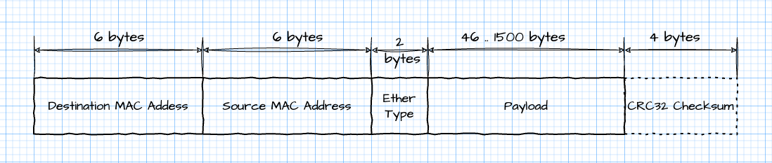
You can often find information about the minimum size of an Ethernet frame, preamble, and checksum. But this is the level of implementation of the network adapter driver or the hardware implementation of the adapter itself, so I will not consider it in the article. For us, an Ethernet frame contains the recipient’s MAC address, the sender’s MAC address, the frame type, and the data itself.
The original description of the protocol can be found in RFC 791 Internet Protocol – DARPA Internet Program Protocol Specification .
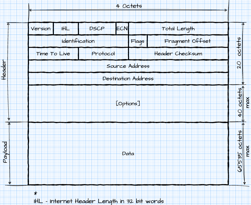
Package structure
The structure of an IP packet is shown below.
IP packets and IP datagrams
IP protocols can transmit data in segments. There are two similar terms in the literature: IP datagrams and IP packets. Sometimes these terms are used incorrectly. Let’s explain the difference: An IP datagram is data transmitted to the network layer, while an IP packet is data transmitted over an IP network; the size of an IP datagram is limited by the maximum value of the Total Length field (Maximum Transmission Unit), which is the maximum amount of data that can be transmitted in one frame at the channel level. Fragments are used to transmit IP datagrams, containing more useful data than a single IP packet can hold.
Fragmentation of IP datagrams
The IP protocol supports fragmentation of IP datagrams. The essence of fragmentation is that the maximum data size of a single IP datagram is 65535 bytes (octets), while the maximum data size that can fit into a link layer PDU (MTU) is much smaller (typically around 1500 bytes). datagram exceeds the MTU, it is divided into several IP packets, each of which can be transmitted in a PDU of the channel level; when IP packets are received, they are grouped into an IP datagram that is analyzed at the transport layer.
All IP packets of one IP datagram have the same value in the Identification field, and the Offset field contains the offset in the payload of the IP datagram.
Although fragmentation allows hosts on different networks to be connected, it should be avoided because it complicates data transmission and increases network load due to the creation of new IP packets and recalculation of checksums. Therefore, it is desirable that the TCP segment or UDP datagram has a size of no more than MTU by routing IP packets.
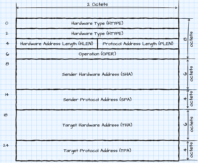
The ARP protocol is used to determine the MAC address of the host’s physical interface from its IP address. The protocol is described in RFC 826 – An Ethernet Address Resolution Protocol. The MAC address does not have to be an address on the Ethernet network, but below I provide the structure of an ARP message for an Ethernet network.
The description of the protocol is given in RFC 792 (Internet Protocol DARPA Internet Program Protocol Specification) .
Structure of messages
There are many different messages in the protocol description, but it is enough for us to start with the Echo and Reply messages
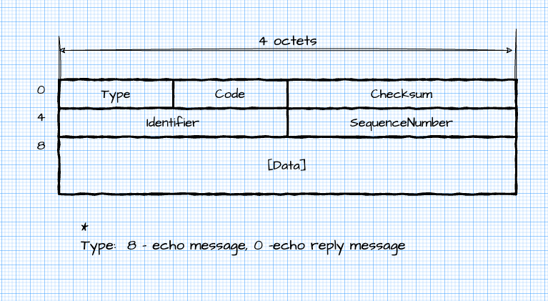
Although the messages used by the protocol are encapsulated in IP datagrams, ICMP is considered at the same level as network IP.
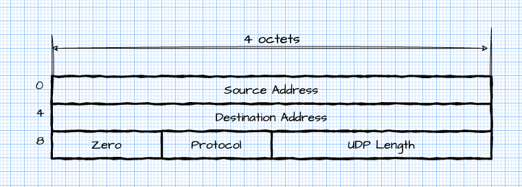
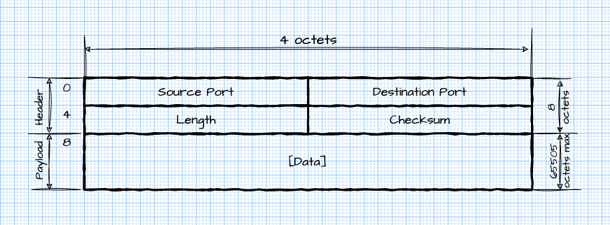
The description of the protocol is given in RFC 768 (User Datagram Protocol) .
The protocol allows two processes to exchange UDP datagrams. Each UDP datagram contains the sender’s port (Source Port), the recipient’s port (Destination Port), the length of the datagram (Length), the checksum (Checksum) and the transmitted data.
When calculating the checksum, a pseudo-header is added, which is transmitted, only participates in the calculation of the checksum.
The protocol is used as a transport protocol where duplication of received data, omission of data or the order in which the data will be delivered is not important at the transport layer.
Typically, handling of these cases relies on application layer protocols or is not handled at all. For example, streaming video or audio data is skipped, as retransmission of the data is pointless in this case. But if you want guaranteed data delivery at the transport layer, you need to use the TCP protocol.
The structures of the pseudo-header used in the calculation of the checksum and the UDP datagram are given below.
The TCP protocol is the most complex of all those given in the article. The purpose of the TCP protocol is to create a reliable virtual full-duplex connection between processes. At the moment, the most recent description of the protocol is given in RFC 9293 – Transmission Control Protocol (TCP) .
Structure of messages
The messages used in the TCP protocol are called TCP segments. Please do not confuse with network segments. They have nothing to do with them. When calculating the checksum for the TCP segment, as well as UPD, a pseudo-header is used. But if the UDP checksum calculation is no longer mandatory, then it is mandatory for TCP.
The structure of the pseudo-header and TCP segment is shown below.
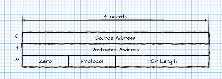
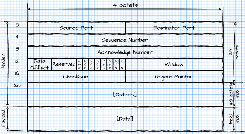
As can be seen from the structure of the header, the TCP protocol, like the IP protocol, has built-in possibilities for the extension and evolution of the protocol using the Options field.
Key concepts needed to understand TCP:
Segment;
Sequence Number;
Acknowledge number;
TCP Window;
TCP Handshake;
MSS – Maximum Segment Size;
TCP Flags and TCP Options;
Window Scaling;
Selective Acknowledgement.
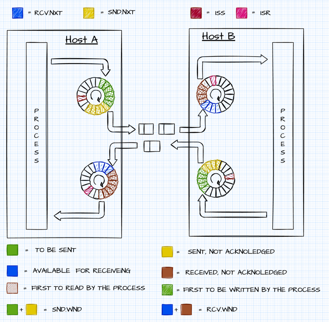
Sequence Number, Acknowledge Number and Window Size are used for reliable transmission. Let’s consider how they work together. Data is divided into TCP segments.
Each TCP segment is assigned a Sequence number.
Sequence Number can take values from 0x00000000 to 0xffffffff. If each transmitted byte is numbered and segmented, the Sequence Number is the number of the first byte of each segment.
Sequence Number is used to order segments that arrived out of order, to confirm received segments (acknowledgment), and to resend lost segments (retransmitting).
Each TCP segment transmitted over the network contains the Sequence Number and Acknowledge Number fields. The Sequence Number identifies the segment being sent, and the Acknowledge Number indicates which segment is expected.
The Sequence Number and Acknowledge Number values allow you to track the progress of data transfer over a TCP connection. Each party generates a random number in the range 0 to 2^32, called an ISN. This number is the starting point for generating the Sequence Numbers of the sent segments.
Only segments that fit the window are sent. The size of this window is reported to the sender when the connection is established, but can be changed later.
As confirmations are received from the receiving side, the window moves in a circle. A connection must be established before data transfer. When establishing a connection, the parties exchange the parameters of the future connection. Any party can initiate disconnection.
When establishing a connection, the parties exchange parameters Sequence Number, Acknowledge Number, Window Size, as well as parameters that are transferred to the TCP Options field (MSS, Window scale).
TCP flags
To control the TCP connection, flags are used in the sent TCP segments. The most important are:
SYN – used when establishing a TCP connection;
ACK – means that the segment was received by the receiving party;
FIN – is used for the normal (graceful) closing of the TCP connection;
RST – used in case of emergency closing of TCP connection.
TCP options
The TCP protocol is designed to be extensible using an options mechanism. Options are additional fields that are passed in the header. For example, when establishing a connection, the parties exchange options, Window Scale, MSS. Depending on the stack settings, the TCP timestamp option may be transmitted in the TCP segment. If an option is not supported, it is ignored by the stack.
Opening a connection, transferring data, closing a connection
RFC 9293 provides a detailed description and state diagram for a TCP connection. I will not mention it here. If you wish, you can disassemble it. But I want to say right away that it is difficult to read. Below is a sequence diagram for the life cycle of a TCP connection.
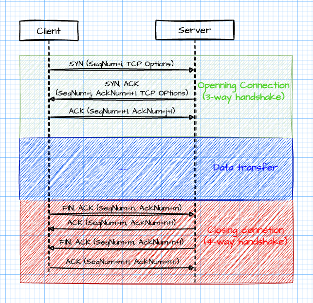
Notice how the values in the SequenceNumber and AcknowledgeNumber fields of the segments given by TCP change.
If a 3-way handshake is used when establishing a TCP connection, there are many different options for closing. The diagram shows the 4-way handshake that will occur if the server has not processed all the data from the client when receiving the TCP segment FIN, ACK. If the data is all processed, then a 3-way handshake is performed (the server sends only the FIN, ACK segment).
To make it clearer for you in the mechanism of transmission and reception of TCP segments, I drew a schematic diagram.
Configuring the TCP/IP stack
The operation of the TCP/IP protocol stack can be configured in the operating system, but it is better to do this if you are aware of exactly what you are changing and why.
In Windows, the stack can be configured with the netsh command, in Linux/MacOS – with the sysctl command. Depending on the operating system, the list and default values of the parameters may differ. For example, Windows tcp timestamps are disabled by default. To enable, you need to execute the command:
netsh int tcp set global timestamps=enabled
In Linux, on the contrary, tcp timestamps are enabled, if you want to disable them, you need to execute the command:
sysctl -w net.ipv4.tcp_timestamps=0
In MacOS, you will not be able to enable/disable tcp timestamps.
To work in a TCP/IP network, the host must be configured. At a minimum, it is necessary to specify its IP address and subnet mask. Gateway and DNS server addresses may also be required. The DHCP protocol allows the host to obtain this data automatically from the network.
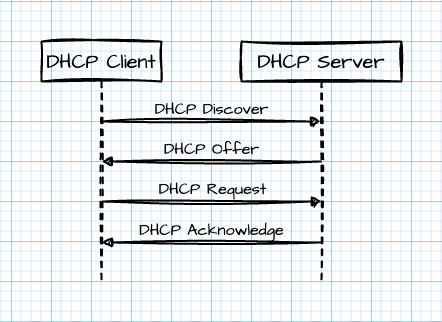
There are various uses of this protocol, but we will look at the basic successful scenario of a host obtaining an IP address consisting of 4 messages.
Getting the configuration
1. Initially, the host does not have an IP address and does not know where the DHCP server is located, which can provide it with this information. Therefore, it sends a DHCP Discover broadcast message to its network segment.
2. If there is a DHCP server on the network, it responds with a unicast DHCP Offer message containing the proposed configuration for the host.
3. The host sends a unicast DHCP Request message indicating the IP address assigned to it
4. The server responds with a unicast DHCP Acknowledge message indicating that the host configuration is assigned.
The sequence diagram is shown below.
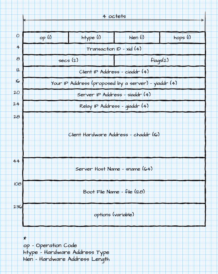
Structure of messages
The protocol is described in RFC 2131 – Dynamic Host Configuration Protocol. DHCP is an extension of the earlier BOOTP protocol (RFC 951 Bootstrap Protocol). Therefore, the header of the DHCP message almost completely matches the BOOTP message. The options field always begins with the magic number 0x62825363, followed by the DHCP options described in RFC 2132 DHCP Options and BOOTP Vendor Extensions.
Each option consists of a code, a length, and one or more message octets. Exceptions are options with codes 0x00 (placeholder) and 0xff (end of options). The size of the DHCP message in octets must be a multiple of four, so an option with code 0xff may be followed by one or more options with code 0x00.
Below is what the DHCP message looks like:
The DNS protocol is regulated RFC 1035 DOMAIN NAMES – IMPLEMENTATION AND SPECIFICATION .
Most likely, you are familiar with the DNS service, which is why it is used to translate a host’s domain name into its IP address. It seems that everything is simple, and for a programmer everything is hidden behind a simple API, but this fact makes it difficult to understand the essence of DNS. A host’s IP address is only part of the information that DNS can store.
Programs like nslookup and functions in Winsock or glibc confuse DNS understanding. I would advise you to start learning DNS by experimenting with the dig utility and traffic analysis. DNS should be considered without being tied to IP. DNS is a distributed hierarchical domain database.
To make sure that this is really a database, you can go to the site and see confirmation of this.
Domain
What is a domain? A domain can be defined as a named entity that contains meta-information about itself and is owned by an organization or a private individual. Such information includes the IP address, the name of the mail server used, the names of the name servers serving this domain, etc. To simplify domain management, they are organized into a hierarchy.
Domains do not exist on their own, they are maintained by name servers. Information related to a domain is combined into a zone served by a specific name server.
Zone
A zone is information about domains hosted on a DNS server. The root zone of Internet domains can be viewed here.
The domain root zone is served by 13 root domain servers.
Resource record
The domain name system allows you to store information in a structured way. Domain names are organized into a tree-like structure, the leaves of which are resource records (Resource Record (RR)). Each RR has a class and a type. As a rule, classes can take the following values:
IN (Internet);
CH (Chaos);
HS (Hesiod).
Although the CH and HS classes can be found, their application is specific and it is very likely that you will not encounter them.
But there are many more types of RR, and some of them must be known:
A (Address) – IP address assigned to a domain name;
AAAA (IPv6 Address) — An IPv6 address attached to a domain name;
CNAME (Canonical Name);
MX (Mail Exchanger);
NS (Name Server);
PTR (Pointer);
SOA (Start of Authority);
TXT (Text);
SRV (Service).
Resolver
Domain name services allow you to derive a host’s IP address from its name. This is implemented using a distributed database running on multiple hosts. Hosts typically interact with a local component called a resolver. It can be accessed through operating system APIs or programming language libraries. When executing API functions, the handler checks its local cache for the IP address of the hostname.
If it is not found, it tries to contact the DNS server at the address specified in the configuration. For ease of explanation, what happens next is omitted. Ultimately, the DNS server returns the IP address of the hostname or, if no such host is available, an error.
The resolver places this information in its cache and returns the value of the code that called it; in Linux, the API to the solver is in the glibc library, in Windows – in the Winsock library. Typically, network programming examples show how to use the API to the solver. The practical section shows how to query a low-level DNS server by forming IP packets containing DNS queries.
A simple DNS query looks like this:
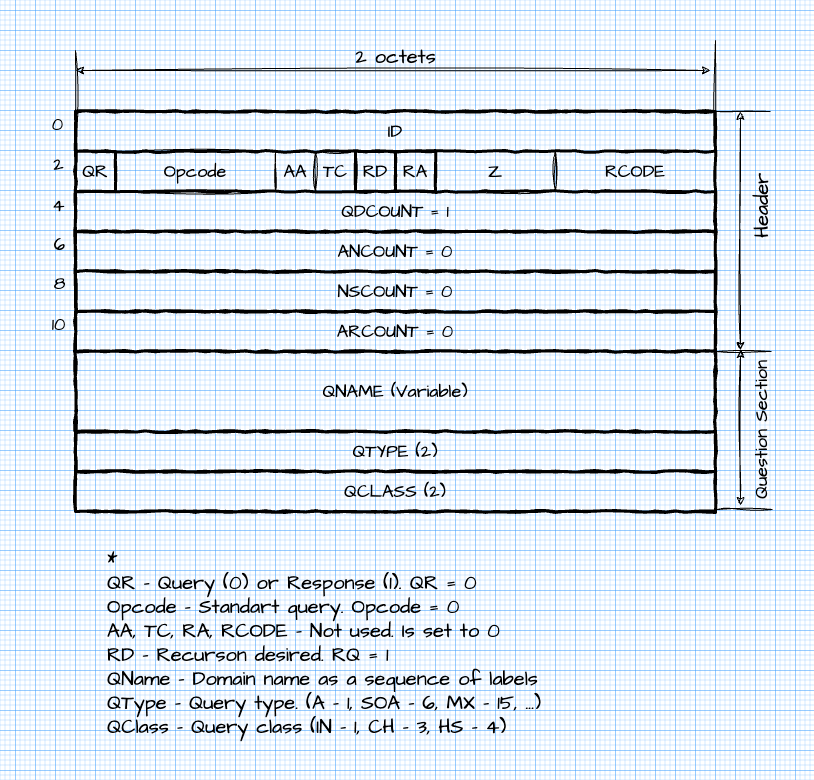
An example DNS response is shown below:
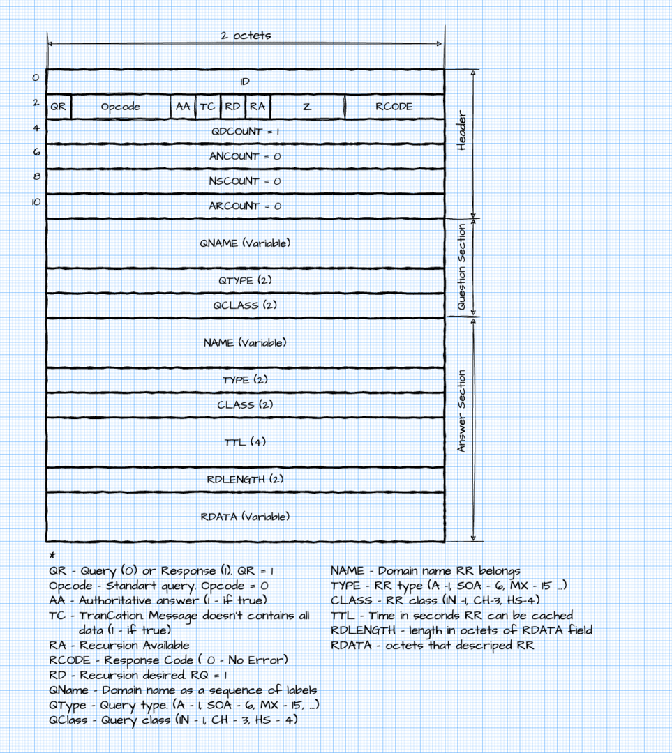
Typically, requests and responses are sent using UDP as the transport protocol. However, if the response is too large, the server will return a TC flag. This means that you need to use TCP as the transport to get the full response.
Virtually any operating system has support for working with the TCP/IP family of protocols. A set of operating system components that provide communication in the form of the TCP/IP protocol family is called a protocol stack. – XPATH – /html/body/div[3]/div[3]/div/div[2]/div/div[14]/p[1]/text() Different operating systems provide access to the stack using different programming interfaces. The most common is the socket interface.
Although there are differences in this interface for different operating systems, most of the functions are similar. Working with sockets involves programming in the C language. However, wrappers are written for different languages that allow cross-platform work with sockets. Depending on the language, wrappers may provide more or less functionality. For example, a wrapper in Python is more platform dependent than a wrapper in Java.
Usually, the literature on network technologies deals with the basics of computer networks, followed by sockets. But how exactly you can create and send a package, the structure of which is described in detail, is not indicated. I want to fill that gap.
Processor instructions in an operating system can be executed in kernel mode or user mode. Most of the code that a programmer writes are processor instructions that are executed in user mode. In kernel mode, driver and kernel code of the operating system is executed.
The TCP/IP stack runs in kernel mode, and from user mode it is usually only accessible by calling API sockets. Therefore, the programmer can only perform high-level operations, such as opening a TCP connection, transmitting data over a TCP connection, or transmitting data as a UDP datagram. It does not have access to the packets being formed.
To access the packets being formed, so-called Raw sockets are used. I note that in Windows Raw sockets have limited functionality. For example, it is impossible to create a Raw socket that would allow working with Ethernet frames. Therefore, a special NDIS driver and the npcap library are used to access the formation of Ethernet frames. In Linux, it is quite simple to create an AF_PACKET Raw socket.
The library provides a high-level, so to speak, API for shaping, filtering, and intercepting packets that hides the implementation details for different platforms.
There is npcap for Windows and libpcap for Unix-like systems; the Scapy Python library allows you to ignore this fact and write platform-independent programs. It also supports many network protocols. It includes tools for analysis, generation and transmission of packets from user space. For example, it can calculate the checksum of IP packet headers and specify the correct Ethertype and protocol when encapsulating the packets. This library is useful for network protocol experimentation and research.
Wireshark is probably the most widely used program for analyzing network traffic. Using a graphical interface, it can write network traffic to disk, filter packets, examine their structure, monitor TCP sessions, etc. Together with Scapy, it is probably the best software for learning the basics of network protocols and conducting various experiments.
Creating an ARP request
def create_arp_request(ip):
    return Ether(dst="ff:ff:ff:ff:ff:ff")/ARP(pdst=ip)
Creating an Echo message used in the ICMP protocol
def create_ping_request(ip):
    return IP(dst=ip)/ICMP()
Creation of DHCP Discover and DHCP Request messages
def create_dhcp_discover(mac):
    return (Ether(src=mac, dst='ff:ff:ff:ff:ff:ff')
            / IP(src='0.0.0.0', dst='255.255.255.255')
            / UDP(dport=67, sport=68)
            / BOOTP(op=1, chaddr=mac_to_bytes(mac))
            / DHCP(options=[('message-type', 'discover'), 'end']))
def create_dhcp_request(mac, ip):
    return (Ether(src=mac, dst='ff:ff:ff:ff:ff:ff')
            / IP(src='0.0.0.0', dst='255.255.255.255')
            / UDP(dport=67, sport=68)
            / BOOTP(op=1, chaddr=mac_to_bytes(mac), ciaddr=ip)
            / DHCP(options=[('message-type', 'request'), 'end']))
Creating a DNS message to receive a Resource Record of type AA
return IP(dst=dns_server)/UDP()/DNS(rd=1, qd=DNSQR(qname=host_name))
TCP connection organization
def create_tcp_syn(src, sport, dst, dport, seq):
    return IP(src=src, dst=dst)/TCP(seq=seq,sport=sport, dport=dport, flags="S")

def create_tcp_ack(src, sport, dst, dport, ack, seq):
    return IP(src=src, dst=dst)/TCP(ack=ack, seq=seq, sport=sport, dport=dport, flags="A")


def create_tcp_fin_ack(src, sport, dst, dport, ack, seq):
    return IP(src=src, dst=dst)/TCP(ack=ack, seq=seq, sport=sport, dport=dport, flags="F")

def create_and_close_tcp_connection(host, dport):
    dst = socket.gethostbyname(host)
    src = get_default_interface_ip()
    sport = 12360
    seq = 1000
    syn = packets.create_tcp_syn(src=src, sport=sport, dst=dst, dport=dport, seq=seq)
    response = send_receive_l3(syn)
    ack = packets.create_tcp_ack(src=src, sport=sport, dst=dst, dport=dport, seq=response[TCP].ack, ack=response[TCP].seq+1)
    send_l3(ack)

    fin_ack = packets.create_tcp_fin_ack(src=src, sport=sport, dst=dst, dport=dport, seq=response[TCP].ack, ack=response[TCP].seq+1)
    response = send_receive_l3(fin_ack)
    ack = packets.create_tcp_ack(src=src, sport=sport, dst=dst, dport=dport, seq=response[TCP].ack, ack=response[TCP].seq+1)
    send_l3(ack)
Since we are interfering with the standard operation of the TCP/IP protocol stack, and the stack is not aware of our interference, it can send RST segments to segments that it does not expect. To prevent this from happening, we will have to temporarily prohibit the sending of RST segments. On MacOS this is done using pfctl. You can use iptables on Linux.
echo "block drop out proto tcp from any to any flags R/R" | cat /etc/pf.conf - | sudo /sbin/pfctl -Ef -
The topic turned out to be quite voluminous and, unfortunately, we could not include everything due to the size of the article. However, we have provided enough material to understand the basics and examples: with Scapy, you can experiment with sending custom packets from userspace with minimal code writing, without having to dive into the jungle of driver programming. Wireshark is also useful for analyzing packets sent over a network and studying their structure.
The examples in this article are not suitable for use in real-world applications and are only useful for understanding the basics of network protocols. In most cases, you won’t need to implement ARP yourself, write DHCP or DNS clients, or implement ping commands. However, experimenting with them will give you a better understanding of network protocols and how a network protocol implementation behaves in various contingencies.