05.12.2025
50 min
641

This article is devoted to a practical introduction to one of the basic tools of radio electronics – the LC probe. The material is built in the format of a training lesson and is suitable for those who want to better understand the principles of measuring inductance and capacitance, as well as the logic of the operation of simple measuring devices.
The article considers an approach to creating a compact device on a microcontroller using modern components. Particular attention is paid to how individual circuit nodes interact with each other, why such solutions are chosen and what tasks they solve in an educational project. The material is presented sequentially, without overloading with formulas, which makes it understandable even for those who are just starting their journey in electronics.
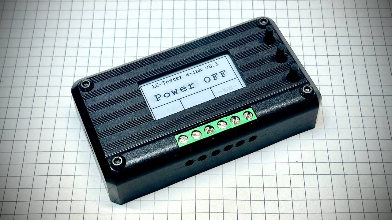
Not every electronic component immediately finds its practical application. Sometimes this requires a good context and the right task. In this case, such a context was a compact probe for measuring inductance, and the key element was a 1.53-inch e-ink display.
This display belongs to older models and does not support a full update of the entire image in one cycle. However, for a device where the readings change slowly, this feature is not a drawback. On the contrary, it fits well into the logic of a simple measuring device for working with homemade or unmarked inductances.
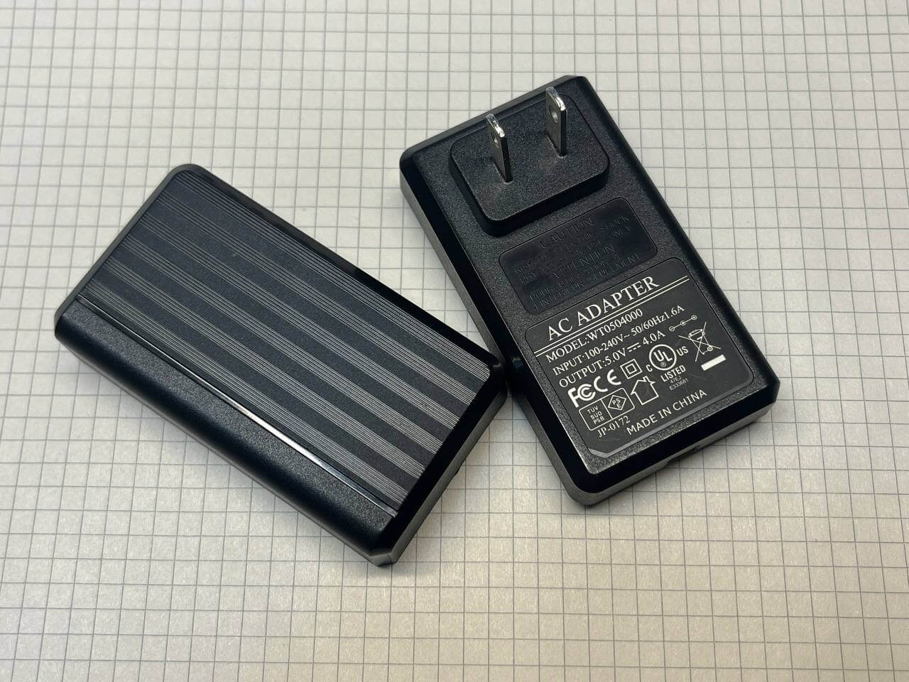
Although a ready-made tester can always be purchased, within the framework of this project the main emphasis is on the practical use of existing components and a clear approach to implementation. Therefore, at the initial stage, the task arose to choose a suitable case without 3D printing and complex design. An old burnt-out power adapter was used as a basis, which turned out to be a convenient option for further processing.
While searching for circuits and methods for measuring inductance, it became clear that measuring capacitance is also not a very difficult task, and the additional determination of the ESR of electrolytic capacitors only increases the practical value of the device. In the process of studying the topic, the well-known “people’s tester” called ArduTester attracted attention – a universal device with open source code and wide capabilities.
Despite the attractive idea of repeating this project, its software part turned out to be too cumbersome to adapt to a specific e-ink display: the code has more than 4,000 lines. Therefore, it was decided to focus only on those functions that are really necessary within the framework of this project, namely – measuring capacitance, ESR and inductance.
The Atmega328P was chosen as the microcontroller, since a large number of ready-made examples of implementing similar tasks are available for it, in particular in the Arduino Nano format. In this case, almost all GPIOs were used. The SPI interface is used both for firmware and for working with the e-ink display, which required the most rational distribution of available microcontroller resources.
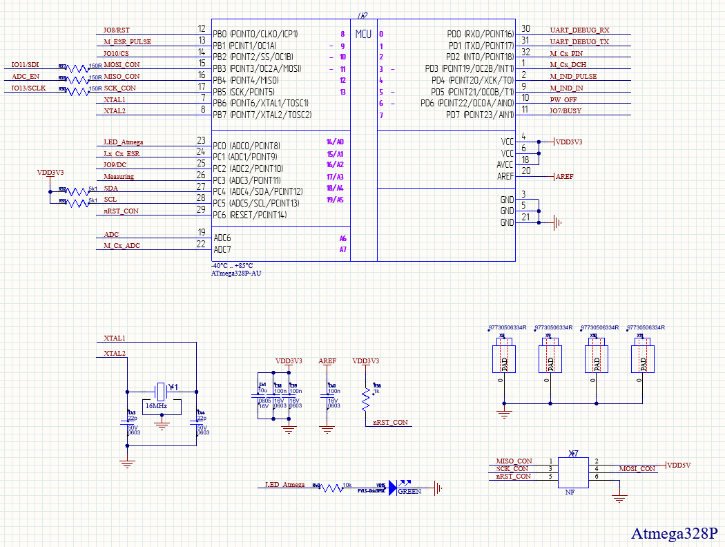
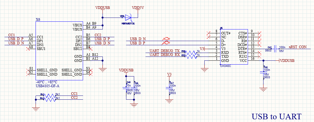
I use UART as a nano for the CH340C converter (note: it does not work without a 100nF capacitor on leg V3).
Some fragments of the circuits were borrowed from the previous development and further optimized in terms of the components used. The device has three control buttons. The S1 button was originally planned to start the measurement process, but later it was decided to use it for calibration, in particular for setting “zero” values. The full-fledged calibration function has not yet been implemented, since its practical necessity is being verified, therefore, at this stage S1 is used for software-hardware shutdown of the device. This approach allows you to correctly display data on the display, and not simply turn off the power.
The S2 button is used to switch between measurement modes. The S4 button is responsible for hardware shutdown of the device.
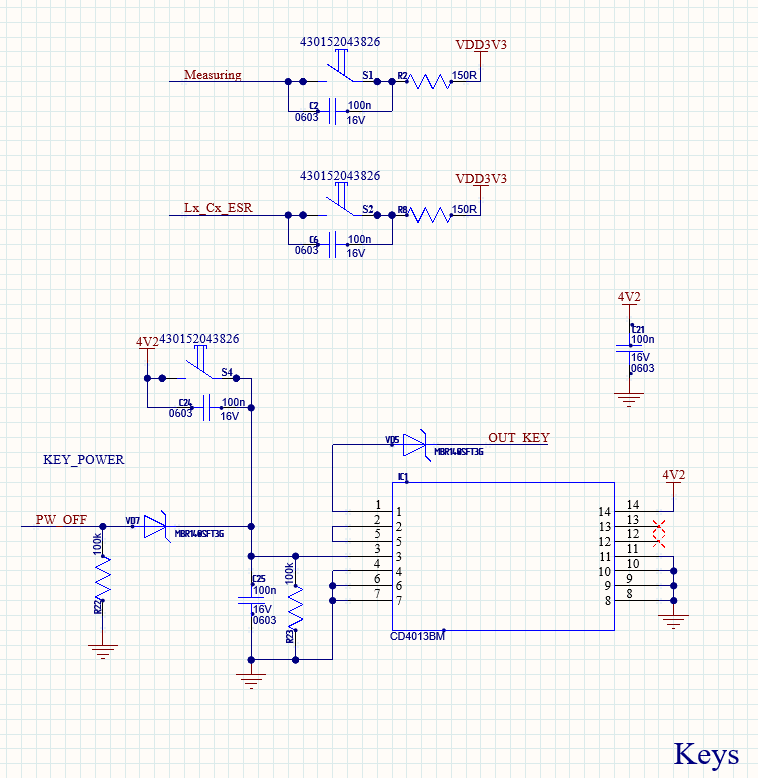
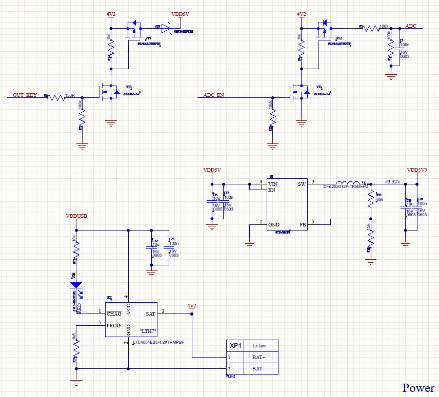
To turn on/off the power and measure the battery charge, I use pairs of N-Channel and P-Channel transistors. When the S4 button is pressed, the CD4013 trigger signal is fed to the power switch. The PW_OFF signal from the microcontroller emulates pressing the S4 button after displaying information on the display. You can also add an automatic shutdown mode when idle.
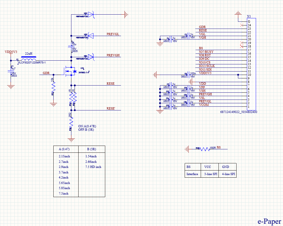
The e-ink switching scheme has already been worked out. I use the 4-line SPI mode. The display is old and supports partial updating only with frames of a certain size. That is, you need to select an area in the display memory, write the data and then display it on the display. The entire page can be updated at once only through a full update with erasure, which takes 2-3 seconds.
There are a lot of circuit options for measuring capacitance and inductance on the Internet. For this project, the simplest solutions in terms of implementation were chosen. One of the key criteria was the availability of ready-made examples of program code, which greatly simplifies development and debugging.
To determine ESR, an external 18-bit ADC MCP3421A0T is used, connected via the I2C bus. There are even ready-made meters on this chip, in particular the HT-RT01 model, a review of which was found in open sources. There are also circuits using the built-in ADC of a microcontroller, but in this case the measurement accuracy will probably be lower.
Inductance is measured using an LM339DR comparator. The measured inductance is connected in parallel with a capacitor installed on the board. A pulse is applied to the input, after which its duration is recorded at the comparator output. Knowing the capacitance of the capacitor and the pulse length, you can calculate the inductance value. Examples of implementing this approach are available in open repositories, in particular on GitHub.
The capacitance of the capacitor is determined by the time it takes for it to charge to 63.2% of its maximum value. In this case, the classical dependence t=R⋅Ct = R \cdot Ct=R⋅C is used, where the resistance of the resistor in the RC circuit is known.
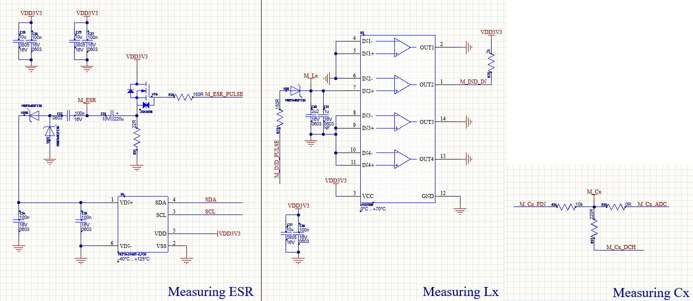
This completes the circuit design. To protect the connectors in case of hot-plugging of the measured components, TVD diodes are installed, which reduces the risk of damage to the device elements. It was decided not to use small cases – the circuit uses passive components of size 0603 and larger.
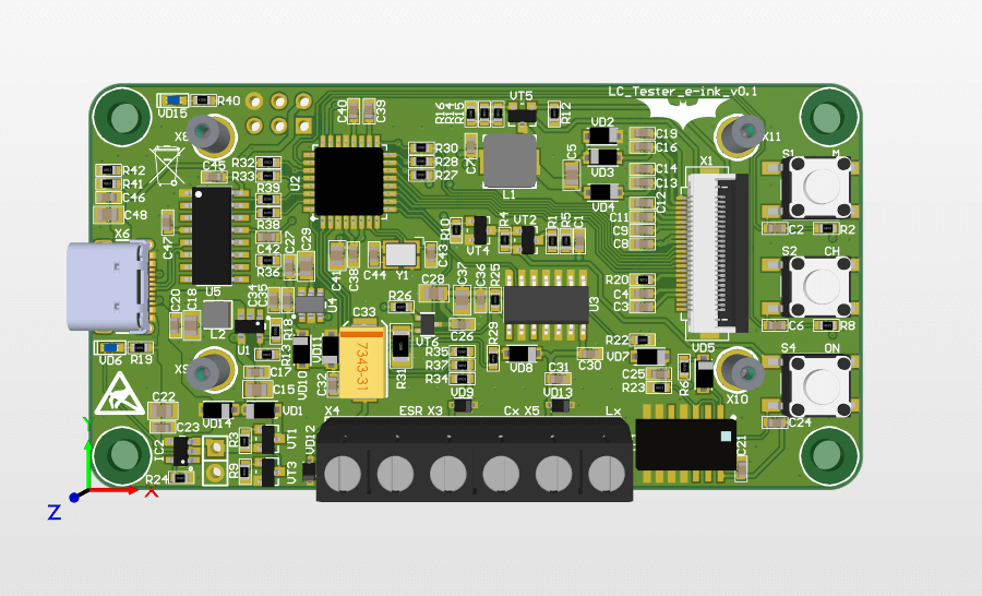
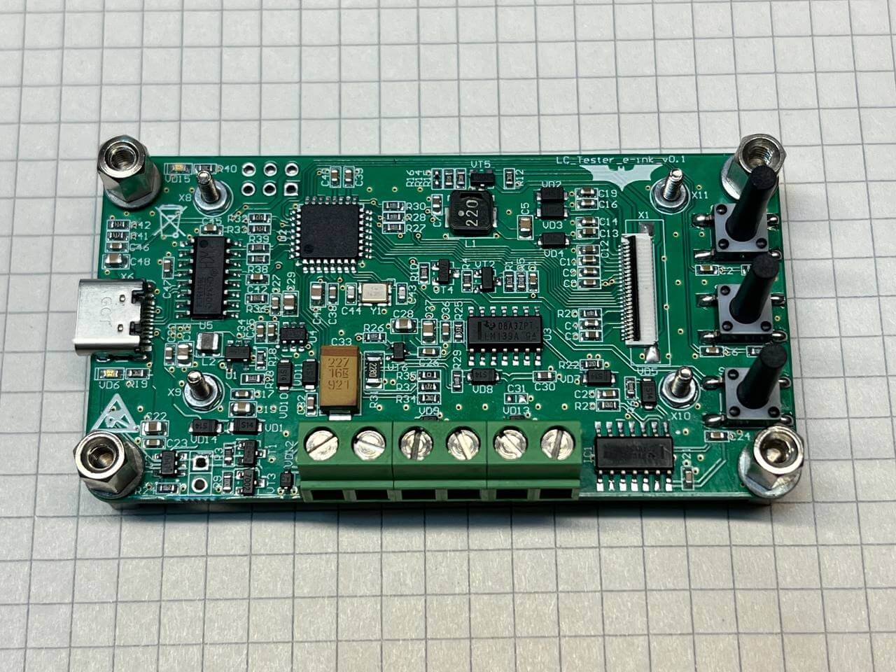
All elements are placed on one side of the board. The layout turned out to be quite dense, but overall neat and convenient for further assembly.
In parallel with the hardware part, the software development and the case fitting were carried out. It was decided not to use a Dremel to avoid the risk of damaging the case. The holes were made by carefully drilling, after which the shape was adjusted manually using a file.
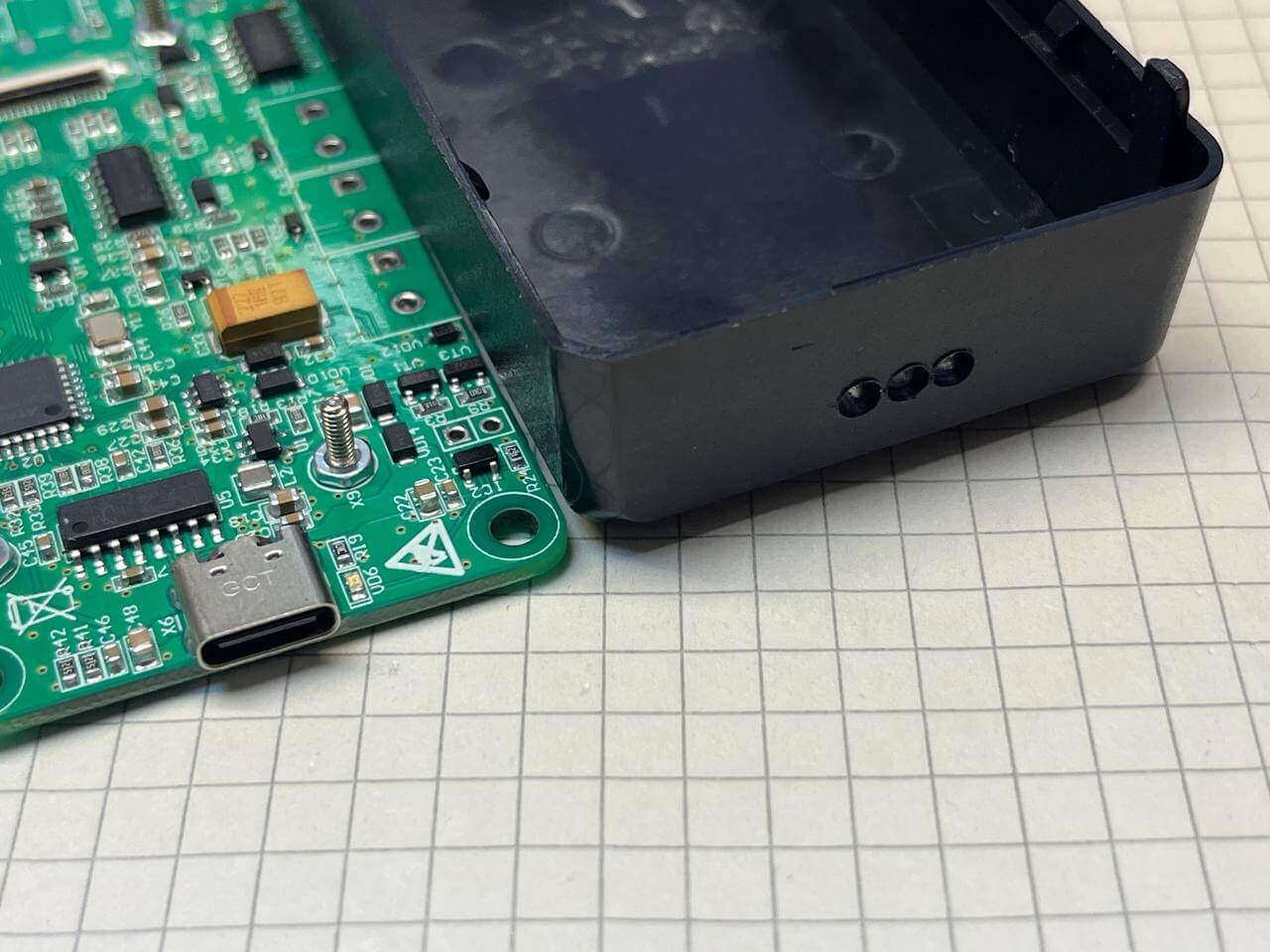
Next, holes for mounting the board, buttons and a cutout for connectors. The main thing here was not to rush and to measure everything well.
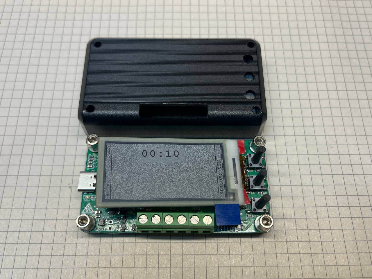
As a result, all the elements were correctly connected to each other. Fig. 11 shows a separate frame of the timer update. It is these rectangular areas that are supposed to update the information on the screen with a frequency of once per second.
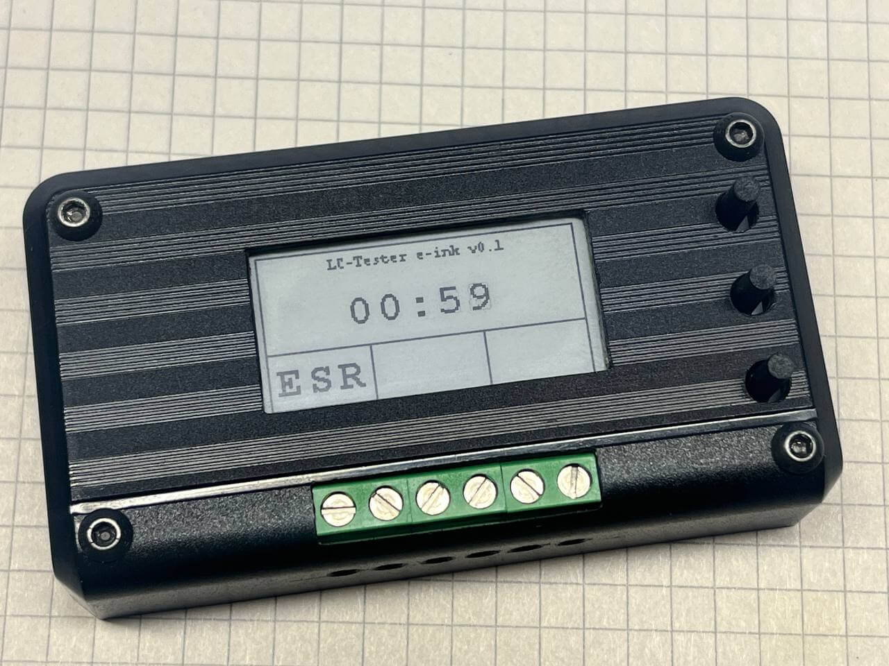
Fig. 12 shows an example of incomplete redrawing of the number “9”. Due to multiple partial updates, such a field may lose clarity over time, and then a complete screen cleaning would be required. In this case, this situation is not critical, since measurements are performed infrequently, and after turning the device off and on again, the screen is completely updated.
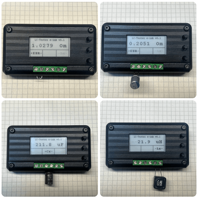
After completing the development of the software part, it became possible to proceed to test measurements (in the photo below). To check the correctness of the ESR measurement, a 1 Ohm resistor with a tolerance of 1% was first connected, which made it possible to verify the correct operation of the algorithm. Next, a capacitor was connected – the measured ESR value was 0.20 Ohm, which looks quite realistic, although there was no possibility to compare the result with another device. The capacitance of the 220 µF capacitor was 211.8 µF, while the MV6013A device showed 211 µF. For a coil with a nominal value of 22 µH, the probe determined the inductance at 21.9 µH.
During testing in a wide range of values, the error remained within acceptable limits. One drawback was also revealed – the measurement of large-capacity electrolytic capacitors is accompanied by a long charging time. It remains to compare the ESR indicators with some third-party tester.
This probe does not claim to be a metrological device, but it allows you to quite confidently assess the condition of the capacitor or determine the inductance of the coil without marking.
The result is a simple but quite workable measuring probe that copes well with its main task – determining capacitance, ESR and inductance in household and educational scenarios. The project is not focused on laboratory accuracy or metrological certification, but demonstrates a balanced compromise between the complexity of implementation, measurement accuracy and practical benefit.
The use of an e-ink display justified itself due to the low dynamics of data update, and the selected measurement methods showed acceptable stability and repeatability of the results. Despite some limitations, in particular the long measurement time of large capacitances, the device allows you to quickly assess the condition of electrolytic capacitors or determine the parameters of unmarked coils.
The project clearly shows that even with a minimal set of available components and without complex software logic, you can create a useful tool that covers specific practical needs and at the same time serves as a good training base for further experiments.