This article discusses a practical approach to designing a compact computer based on the SMARC modular platform, a form factor that is actively used in embedded systems, industrial solutions, and edge devices.
The material will be useful for those who are interested in hardware development, plan to work with modular computers, or want to better understand how the case, board, interfaces, and cooling system are combined in a real engineering project. The emphasis is on practical experience, decision-making logic, and typical nuances that developers encounter when creating compact PCs.
The project was started not with the selection of interfaces, as is usually done, but with the choice of the case. The main requirement was the most compact dimensions, taking into account the SMARC module measuring 82×50 mm. The cube format was immediately rejected, so the height was limited to 30–40 mm — this is enough to accommodate the cooling system.
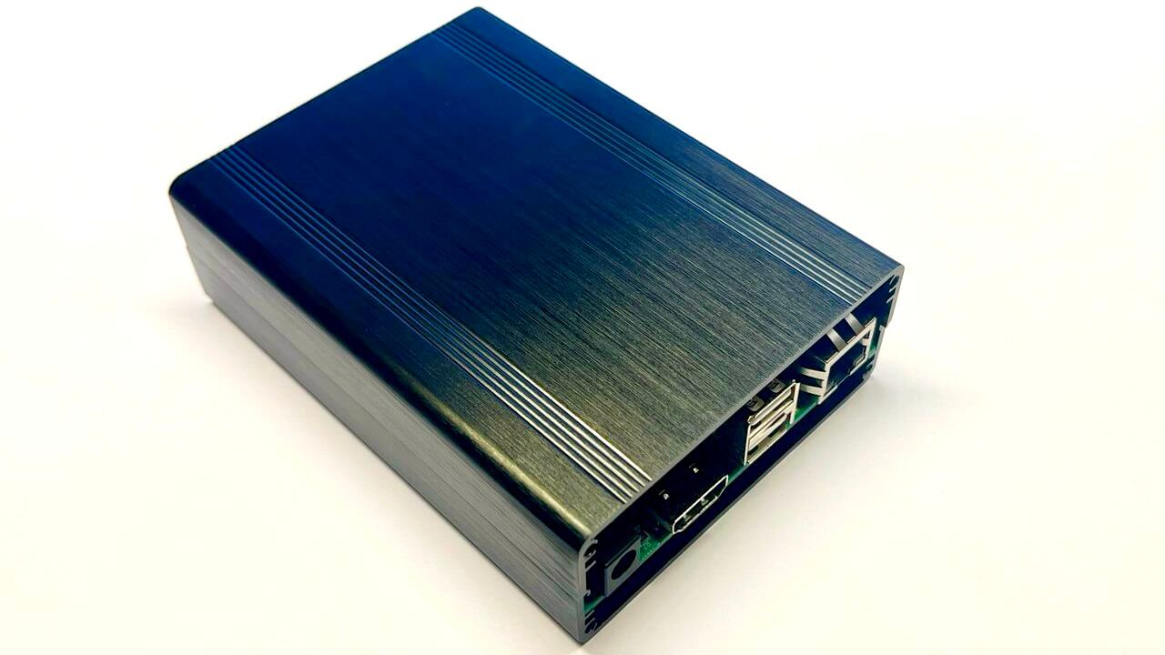
After a short analysis of the available options on the network, a successful solution was found — a case measuring 120×88×38 mm, made of black aluminum. This format combines compactness, strength and heat dissipation potential well, so the choice was made on it.
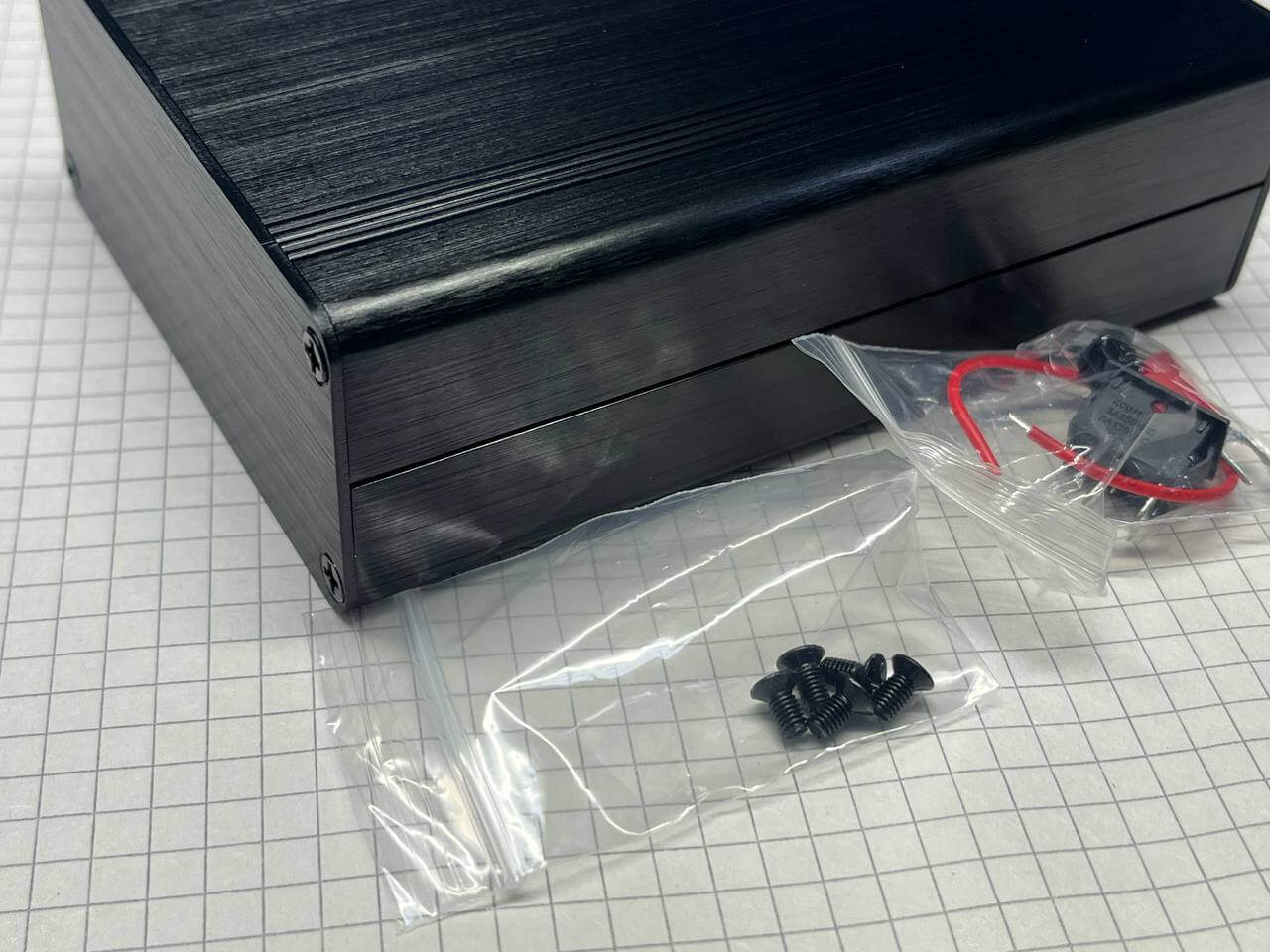
The delivery set even includes small niceties: spare screws, a switch and a small piece of wire (although only one). The case was deliberately chosen with collapsible side panels that are fastened together – this format greatly simplifies setup, testing and measuring temperature conditions during operation.
Externally, the design looks neat and attractive, creating a feeling of a well-thought-out and high-quality product.
The SECO Intel Atom x6425RE module (SOM-SMARC-EHL (C93)) was used for the project, which was already available and is based on the Intel platform. It is equipped with a fairly productive quad-core processor with a clock frequency of 1.9 GHz. In addition, the board is equipped with a 64 GB eMMC storage, 16 GB LPDDR4x memory and a full set of modern interfaces, which makes the module versatile for various usage scenarios.
Even before ordering the case, it was decided to clearly define the required set of functions and think over their location. This allowed us to estimate the dimensions in advance, avoid component conflicts and make sure that all elements would be correctly placed inside, without interfering with each other and maintaining the optimal layout.
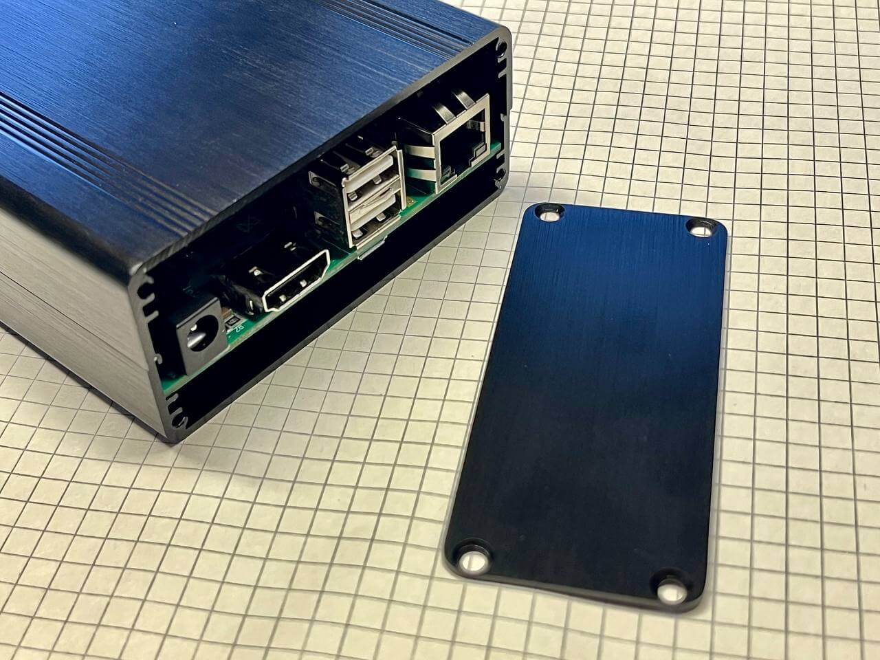
On the back wall is displayed:
Power supply 12 V. The 5 A power supply unit provides the entire system, including peripherals and load margin, without any problems.
HDMI. There are combined HDMI + DP connectors, but in this case it was decided to distribute the interfaces separately on a four-layer board. This made it possible to correctly place a large number of high-speed data lines and leave room for internal modules.
2× USB 2.0. The internal Wi-Fi / Bluetooth module was abandoned in favor of external USB dongles located on the back panel. The second port is used to connect a wireless keyboard and mouse.
Gigabit Ethernet. Despite the planned Wi-Fi support, it was decided to keep the wired network interface as a more stable and versatile connection option.
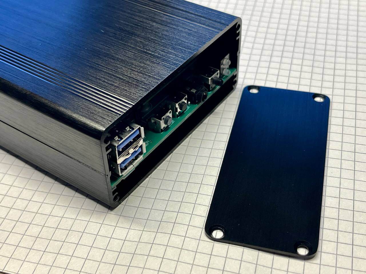
The front panel features controls and interfaces focused on everyday use and ease of access:
Power and activity LEDs. The presence of an indication allows you to quickly assess the device’s status. An additional drive activity LED was considered, but it was decided to abandon it.
On/off button. It is planned to be possible to configure the operation of the button to enter deep sleep mode.
Headset jack. Separate lines for headphones and a microphone are displayed on the front panel; the choice of audio codec is discussed separately below.
Two service buttons: reset and recovery. The buttons are made recessed, with the expectation of being pressed with a thin object to avoid accidental activation.
2× USB 3.0. For high-speed connections, Type-A connectors were chosen instead of Type-C for practical reasons. Despite the desire to implement a universal format, including power via Type-C, a more classic and reliable solution was chosen.
Since we have already touched on the audio codec, it is worth continuing this topic. The module used supports the I2S interface, for which a circuit based on the NAU88C22YG was developed – a successful and proven solution for such tasks. As in most similar cases, the codec configuration requires an I2C interface, through which its settings are performed.
In practice, an unexpected difficulty arose: while working with the BIOS, it turned out that the number of parameters and configuration options significantly exceeds expectations. Despite the time spent, it was not possible to find a clear way to bind a specific I2S audio interface to the desired I2C bus.
An additional issue was the drivers. Taking this into account, it was decided to reconsider the approach and pay attention to an alternative. There were two free USB 2.0 ports on the SMARC platform, which were not displayed as connectors due to space limitations. This opened up the possibility of using a USB audio solution.
In the end, the choice fell on the PCM2912 — a USB 2.0 audio codec with one microphone input and stereo output. This approach turned out to be much simpler: ready-made drivers for this chip are already available for both Windows and Linux, which significantly simplifies integration. That is why this option was recognized as optimal for the current project.
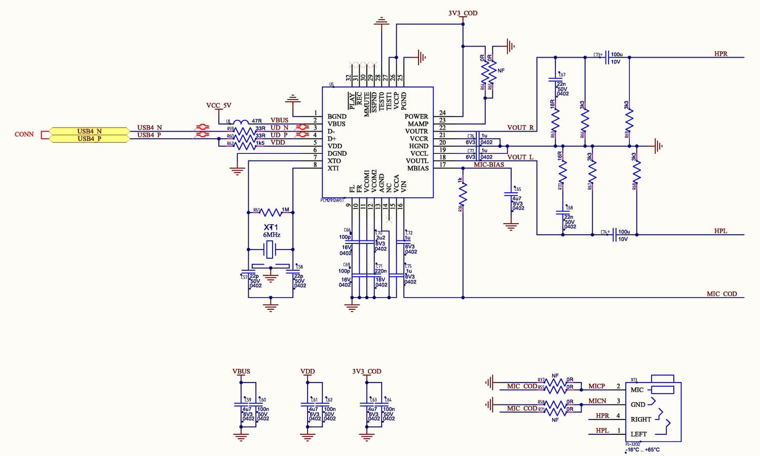
It only requires 5V to power it. It turned out to be an excellent and simple solution.
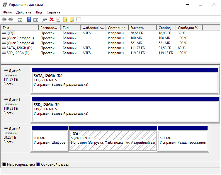
The module board already has a 64GB eMMC drive, but to expand the storage capabilities, it was decided to add several interfaces for connecting SSDs.
The following elements and connectors are provided:
mSATA SSD connector in mini PCI-E form factor (52 pins), allowing the use of compact SATA drives.
M.2 NGFF SSD connector (75 pins) with PCIe 3.0 ×4 support, focused on high-speed NVMe drives.
Two microUSB connectors, paralleled with Type-A (USB_OTG), eliminating the need for non-standard or adapter cables.
CR1220 battery for RTC. The use of a larger battery was impossible due to size restrictions; the only alternative would be a vertical holder.
Connector for connecting a cooling system fan with speed control and the ability to select a supply voltage of 5 V or 12 V using a jumper. The BIOS provides settings for the fan type – 3-wire or 4-wire.
DIP switch located under the module to select boot modes: eMMC, SATA, PCIe, USB and other available options.
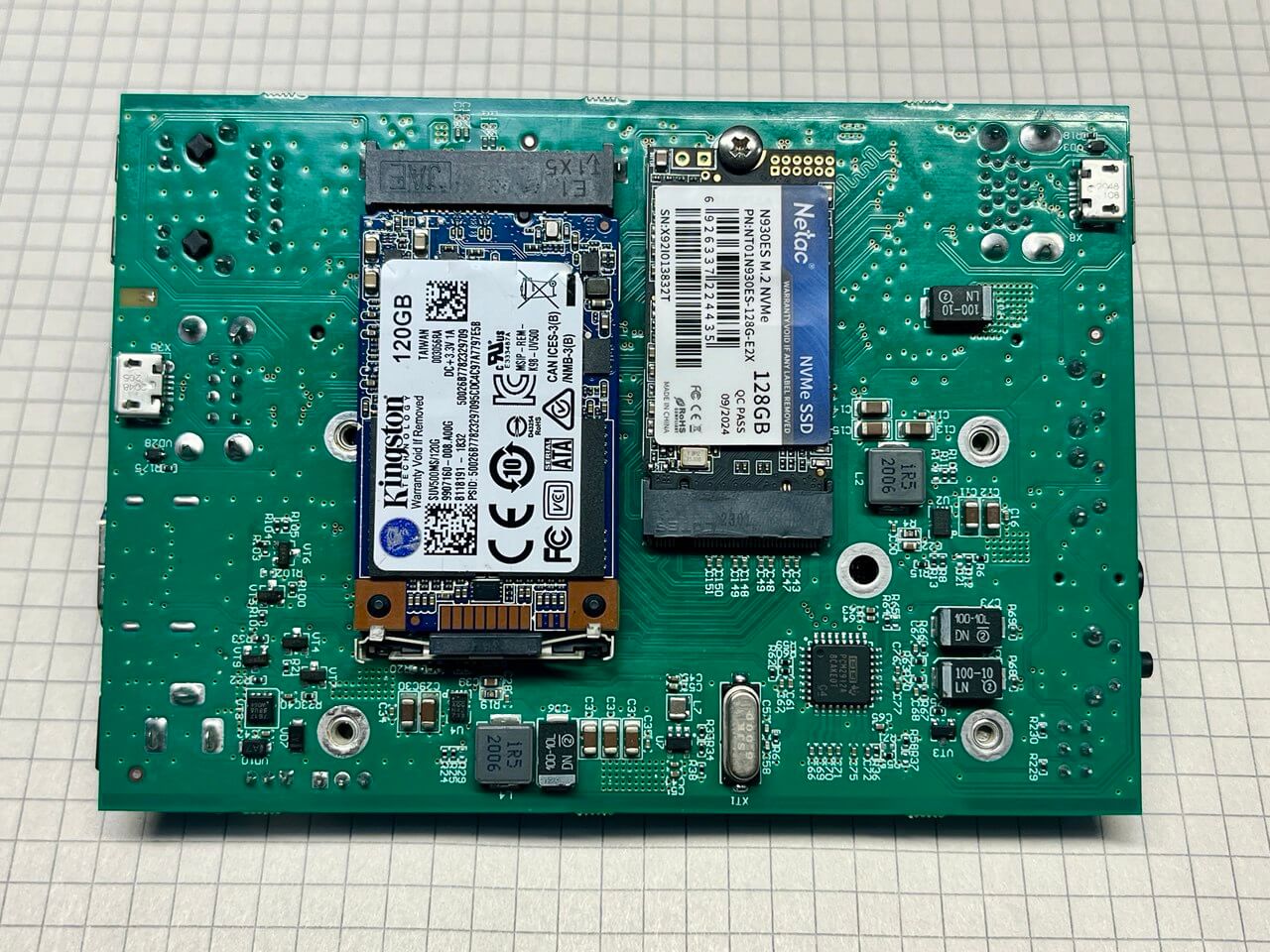
On the bottom side of the board, in addition to the SSD, there are power supply units, a fan control circuit and an audio codec. Compared to the M.2 form factor, the mSATA drive turned out to be noticeably larger in size, which complicates the compact layout.
The module is powered by a 5 V voltage via a separate MP8759GD DC/DC converter with a maximum current of 8 A. A similar buck converter is used to form the 5 V USB line. Then the voltages are distributed via two additional 3.3 V and 1.8 V stabilizers, which power the SSD and internal logic circuits. This scheme ensures stability, current reserve and correct operation of all subsystems.
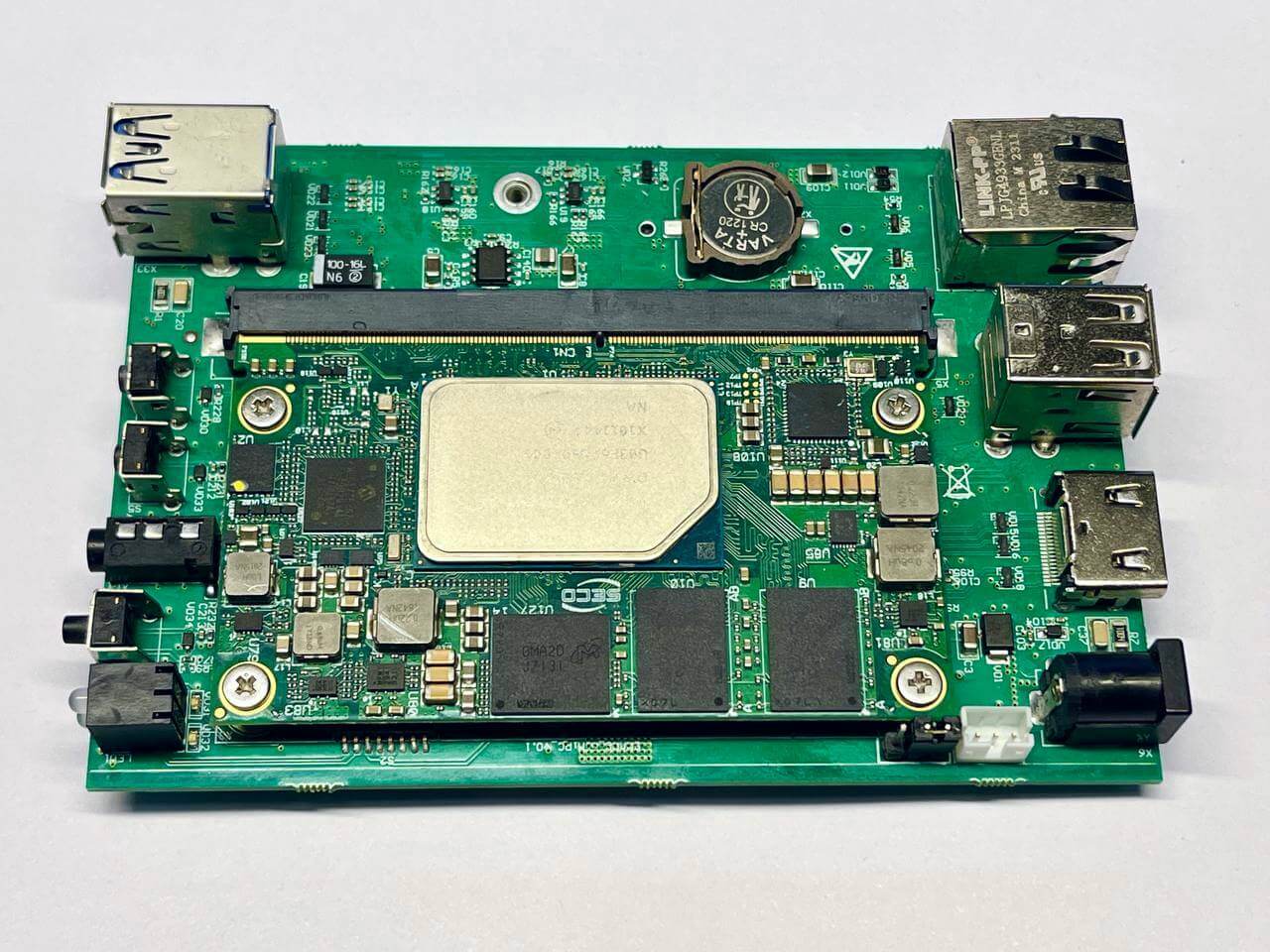
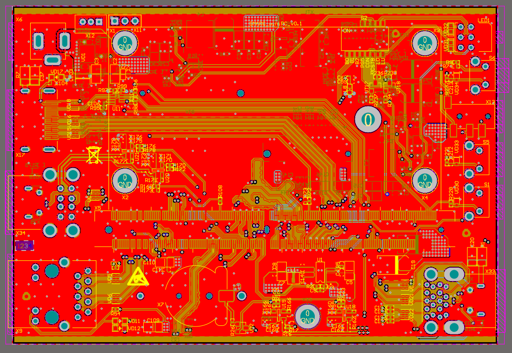
Due to the significant reduction in the number of interfaces and the retention of only the necessary ones, the routing of the board on four layers did not cause any particular difficulties. The idea of placing all components on one side of the board was considered, but this approach would require an increase in the dimensions of the structure. In addition, for reasons of ease of debugging, it was decided not to place any elements directly under the module, which simplified access and subsequent diagnostics.
After turning on the HDMI image never appeared. At the same time, the signs of life were completely normal: the fan was spinning, the indication was working, all voltages were within normal limits — but there was no video signal.
The search for the cause led to the documentation for the module. The specification directly states: “2×DP++ 1.4 or 1×DP++ 1.4 and 1×HDMI 1.4”. That is, of the two video interfaces, one can really be implemented as DP++ or as HDMI — the logic is clear. For this, a resistor was even provided that sets the interface selection.
The problem turned out to be something else: the interface selection resistor was connected to the wrong line. It was connected to the DP channel that is not used at all on this board (this wiring option was left over from another project). As a result, HDMI was physically “not activated” where it was expected, and the output was a blank screen.
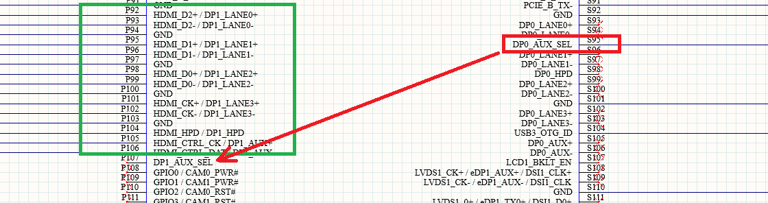
It’s a shame, the only hanging wire on the board.
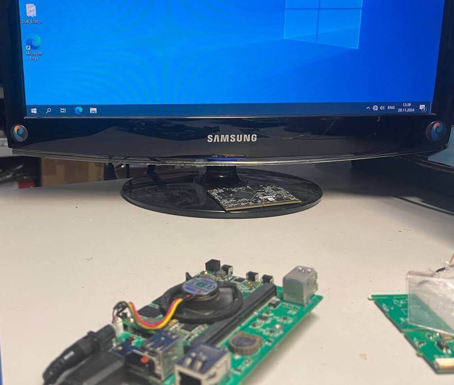
After fixing the error with the video interface, the long-awaited Windows 10 desktop finally appeared on the screen. At this stage, the fan was temporarily simply connected and placed on the board — without a radiator. Under such conditions, the operating temperature during the basic load (installing programs, working with the interface) was kept within 65–75 °C.
The processor has a heat sink of only 12 W, so the system is able to work even without active cooling. At the same time, the heating remains quite noticeable, so a completely passive option looks doubtful. Experiments with a radiator are planned, but it is likely that it will not be possible to do without a fan.
After installing the operating system, it turned out that a significant part of the drivers are not in the standard set. The necessary components were found on the official SECO website in the form of an archive of about 1.2 GB, after installing which the system worked correctly.
The case was purchased, but the practical issue of accurately making cutouts for all connectors remained to be resolved. Manual finishing with a file does not seem like a very good idea – it is long, inaccurate and difficult to repeat. Therefore, drawings are being prepared in parallel with the hardware part: the possibility of milling or other mechanical processing that will allow obtaining even and neat holes is being considered.
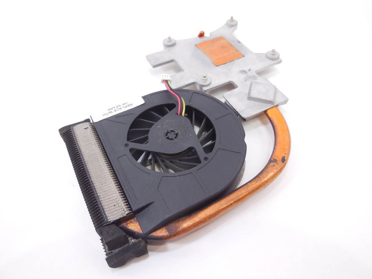
Cooling systems from laptops attract special attention. Given the limited internal space of the case, this approach seems quite logical: compact heat pipes and low-profile radiators can be the optimal compromise between cooling efficiency and dimensions.
This project shows that creating a compact mini-PC based on SMARC is not only about the choice of components, but also about constant compromises between dimensions, functionality and ease of debugging. Even small errors in wiring or configuration can cost time, but at the same time provide valuable practical experience. As a result, we managed to get a workable system with a flexible architecture that has the potential for further refinement – primarily in the case and cooling.