20.03.2024
14 min
3315

You will learn how switches work and their role in connecting different devices in a network. The process of setting up and connecting devices to coils is covered in detail, including the importance of correctly labeling cables and ports to facilitate network management. The focus is on understanding and configuring VLANs to isolate traffic on large networks, improve security, and optimize performance.
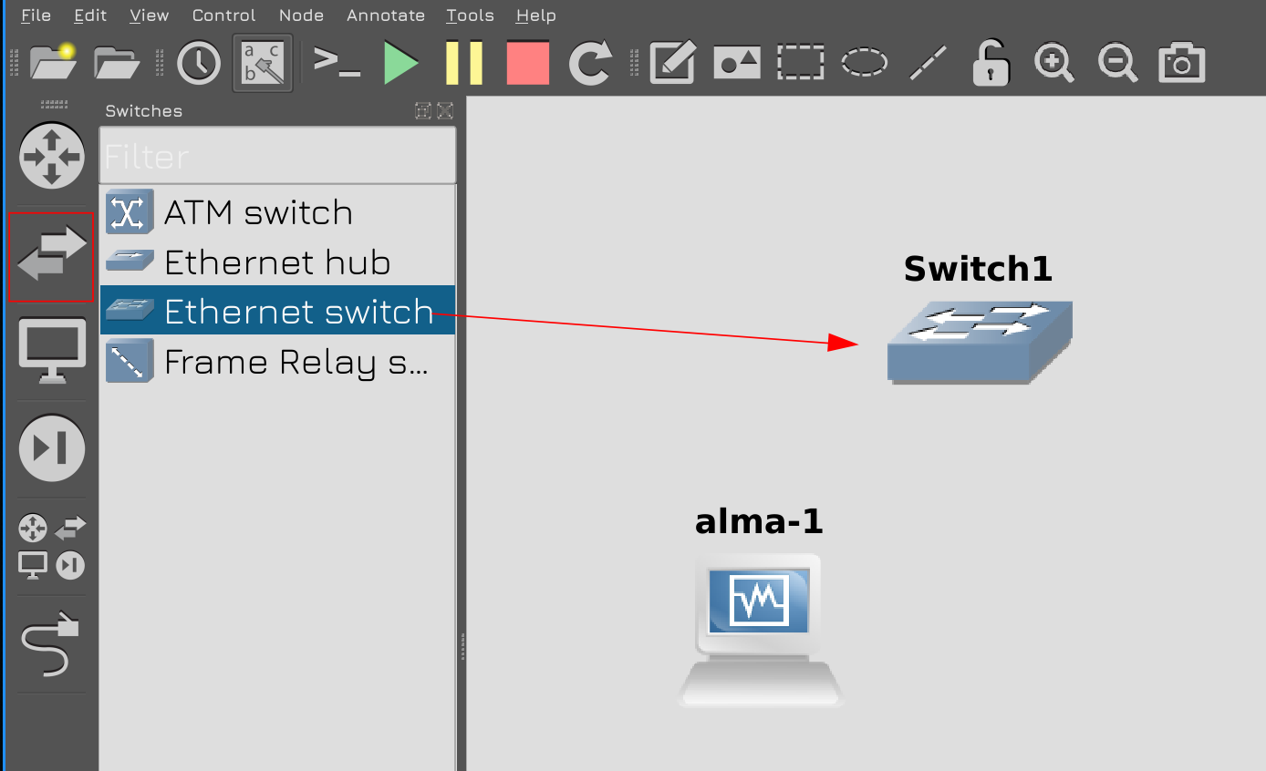
Let’s start building infrastructure from the element that connects everything – light. If you are not familiar with networking, it is recommended that you familiarize yourself with topics 42 and 43 of the GNU/Linux Basics course beforehand. Click on the icon with 2 arrows in the left panel of GNS, select the Ethernet switch and drag it to the center. The official name of the switch in Russian is switch, or network switch. And the GNS icon is a general designation. Network administrators usually manage the switch, but system administrators should understand that they are responsible for connecting the server to the switch and should be able to configure things on their end. In small businesses, the System Administrator is also often responsible for Network Setup.
A switch is actually a device consisting of a large number of ports. It’s primary purpose is to transfer traffic from a cable connected to one port to a cable connected to another. There are small kits with 5-8-12 ports, but for medium and large companies, 24 or 48 ports are most often used. Currently, most switch ports are gigabit, but there are 10 gigabit, 25, 40, and even 100 gigabit ports. In theory, an ordinary computer can witness, but when it comes to high speed, the switch has special chips that process faster traffic.
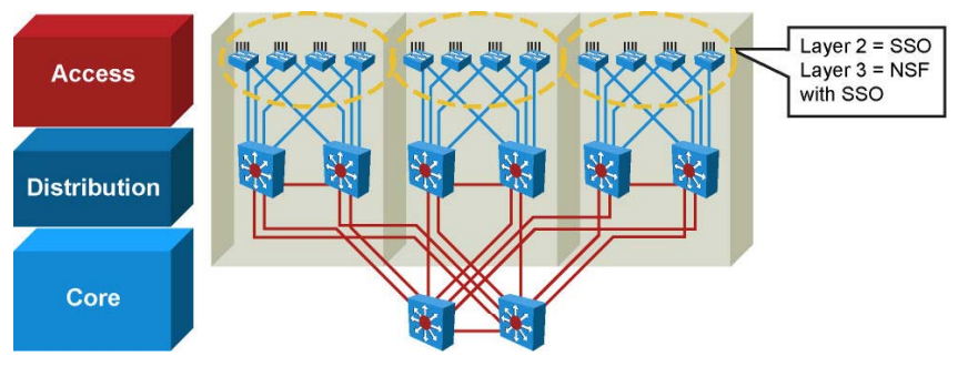
Depending on the task, the network worker divides the switch into several levels (access, division, core). Access switches are typically located on each floor of a building, have multiple Ethernet ports, and are primarily designed to connect users, printers, and other equipment. The length of the twisted pair cannot exceed 100 meters. Otherwise, the signal in the wire will simply disappear. So if the building is large, each floor will have 1 or more scrolls. These switches are also connected to other power distribution switches using 10 gigabit optical cable. A port connecting some switches is called an uplink, which is created with other switches. A kind of output from the switch. The distribution switch is also connected to the core switch through which all traffic passes. In fact, the speed depends on the size of the infrastructure and the volume of traffic – with a small infrastructure, it makes no sense to have such a topology and such a speed. But when the infrastructure grows, everything boils down to this scheme.
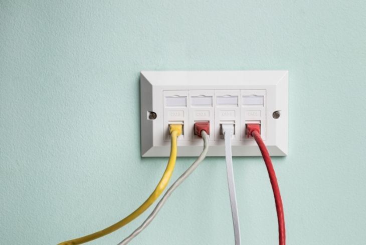
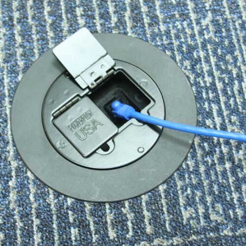
In places where computers or other terminal devices are located – let’s call them endpoints – special sockets are made on the wall or floor, where the copper wire is inserted.
These connectors will lead to a small river and will also appear as outlets, but will be arranged in 1 or more rows. They are called switchboards. And the patch cord goes from the switch panel to access the switch. The connector on the switchboard connected to the connector on the user’s computer is also marked in the same way. Conventionally, everything on the switchboard is located in numerical order – 1, 2, 3, etc. in addition, the outlet behind the first switchboard port is marked 1 in any room. And it is necessary to mark the cable that is connected to the switch from the switch panel – 5 connectors from the switch panel, so that it is clear to which port of the switch it is connected. And tomorrow, if you need to do something, go to the computer and you will see that the socket says 5, which means that you need to look at the 5th port on the switch panel. And there, according to the marking, you will find out to which port on the switch the cable will be connected. Because there can be many wires, which makes it difficult to understand without marking.
Accurate and up-to-date labeling is a task for IT departments, including system administrators. And it would be great if you came across a good contractor who ran the cable, installed the outlet and labeled everything. But you are the one who manages the infrastructure, tomorrow you will buy a new kit, replace the cable, change something – so try to keep the labeling up to date.

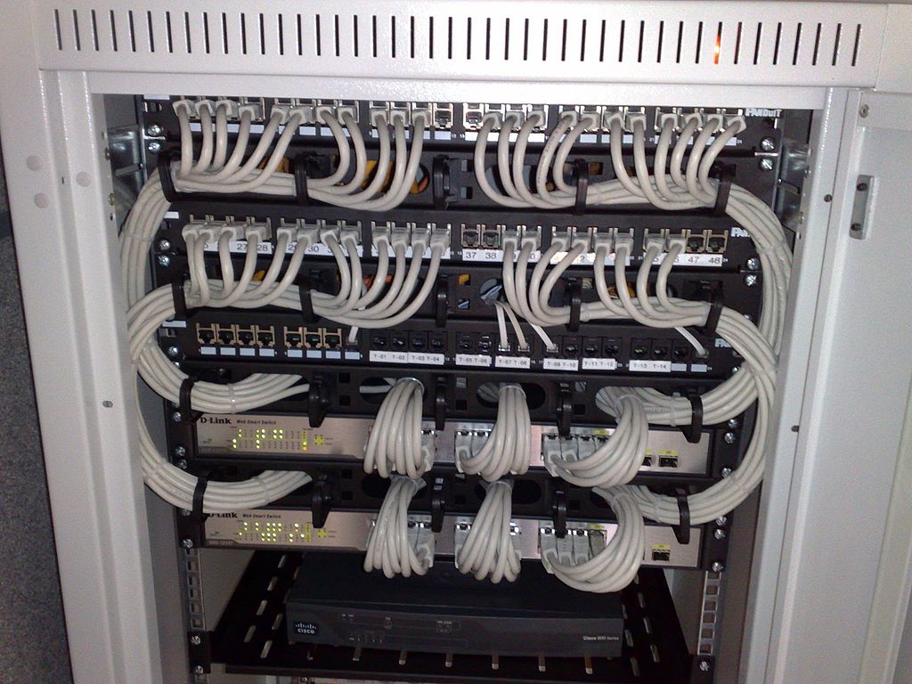
Well, in the server room, when connecting various wires to servers and other equipment – it doesn’t matter, electricity, ethernet, etc. – be sure to label everything as well. For this purpose, there are special devices that print text on adhesive tape – they are called label-printers. And try to keep all labeling according to some standard – you need to describe what is connected very briefly and accurately.
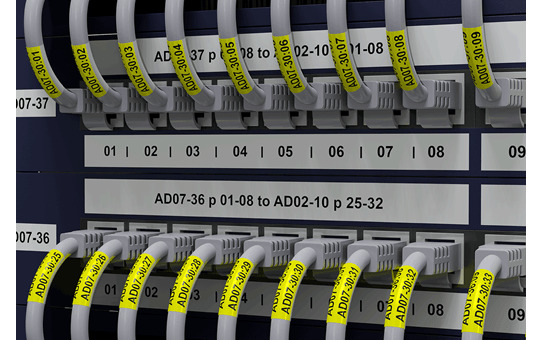
For example, on one side of the wire it says that it will lead to port 3 of the first UPS, and on the other end connected to the UPS, it says that this cable will lead to the 3rd Power Supply of the 2nd server. And all this should fit into a few letters on a thin sheet of paper, and just by looking at it, it becomes clear what it is and what it will lead to. In the event of a problem, try not to accidentally pull out the wire and completely ruin everything. Even if you have a lot of cables, you will always know which wires are connected to what and where.

Go back to the switch. Even if it seems like they are doing light work, they have enormous potential, especially in today’s worldview. But their main task is to connect those who want to be in touch. In the OSI model, this is layer 2, a link often called l2, meaning layer 2. At this layer, devices access each other by MAC address, and the switch remembers which port has which MAC address. For this, candle has a table of Mac addresses.
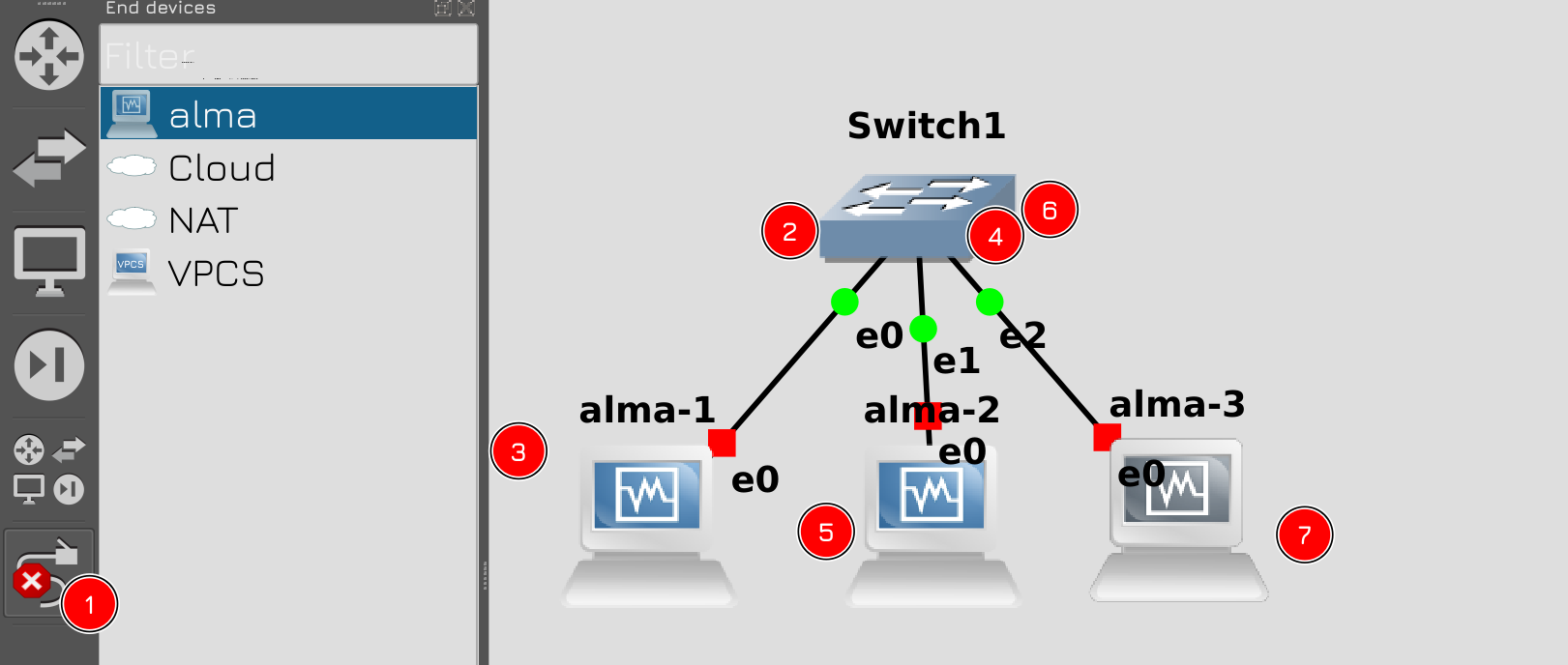
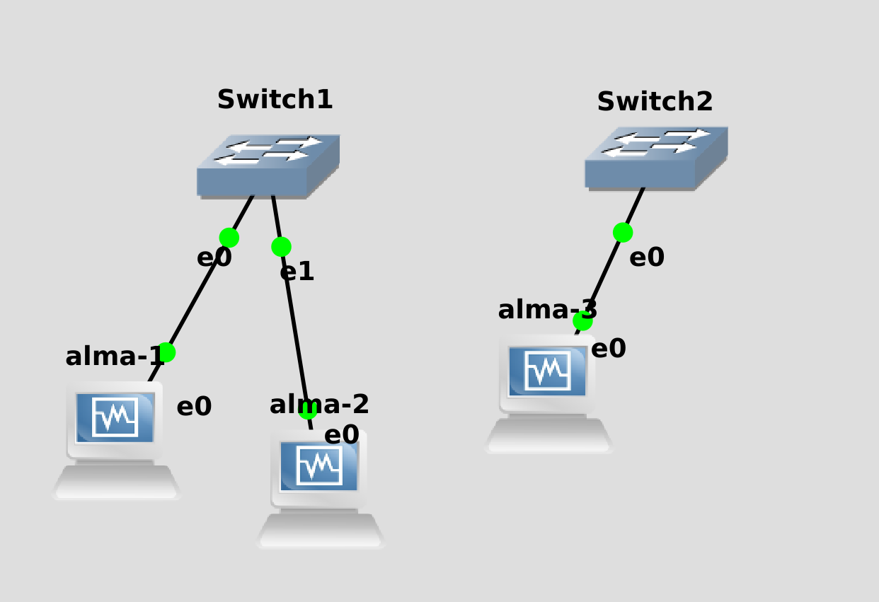
To understand and see this, let’s take 3 hosts. Make sure 1 switch and 3 VMs are using alma. Then in the left panel, click on the last icon that looks like a wire, then click on the switch and select Ethernet0 and alma-1. Press the switch again, select Ethernet1 and press alma-2. Repeat the same for Alma-3. Then right-click or click the wire icon. So we connected everything to one network. It should be noted that the label –e0 appeared with Alma – this indicates that the wire was connected to the null adapter. The last time you configured the 4 virtual machine adapters respectively, their names would be e0, e1, e2 and e3. e0, e1, e2 are connected 3 wires from the side of the switch.
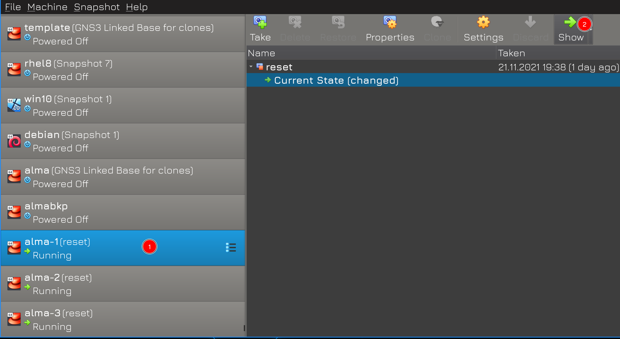
After that, let’s launch all 3 virtual machines. Since our network is not ready yet, I will not be able to connect to them via ssh. Therefore, this time we will resort to the console of virtual machines. Start the virtual box, select the running virtual machines and click show.
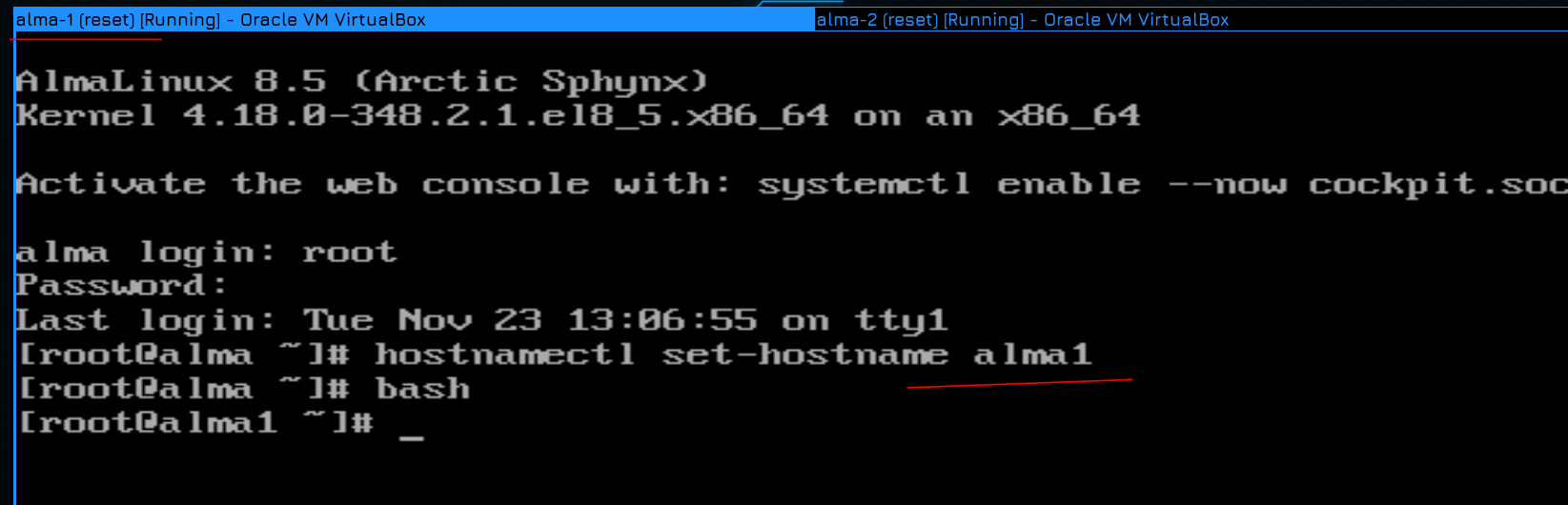
Then name each system accordingly – alma1, alma2, alma3:
hostnamectl set-hostname alma1
hostnamectl set-hostname alma2
hostnamectl set-hostname alma3
Well, roll over, or run bash so that the new name is displayed in the console prompt. This will allow us not to get confused.
Now let’s look at the list of interfaces:
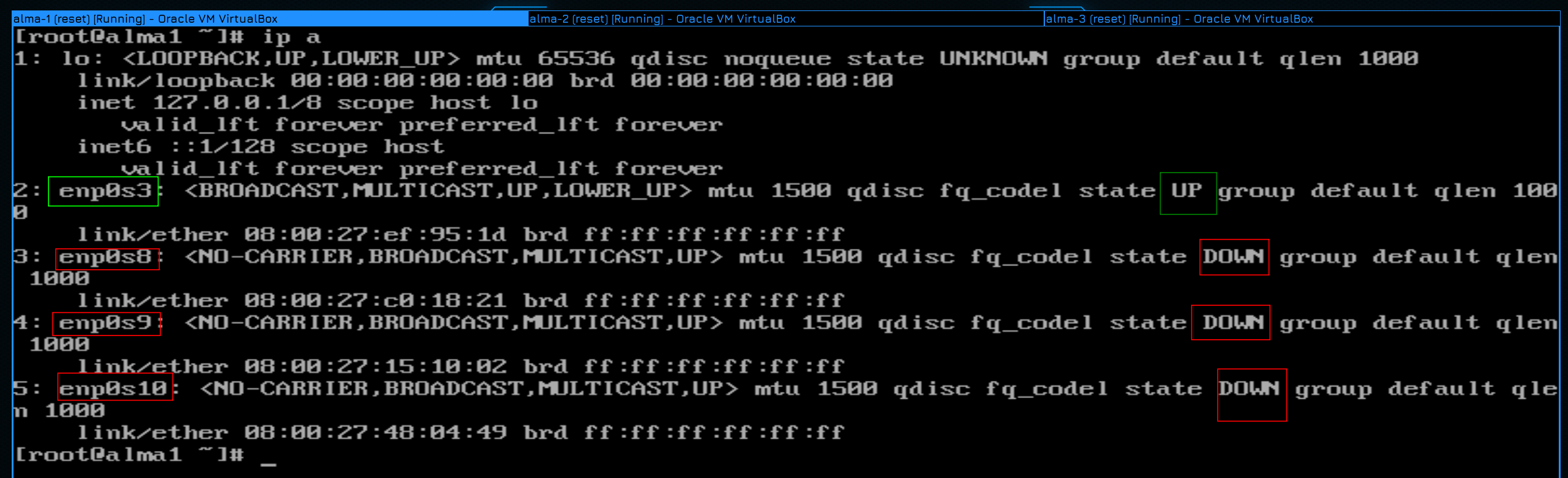
ip a
As you can see, the system shows 4 interfaces, excluding loopback. And only 1 of them is in UP–e-enp0s3. So it corresponds to the e0 interface we saw in GNS. There are only 3 hosts and switches on this network, and there is no DHCP server to allocate an IP address, so the interface has no IP address.
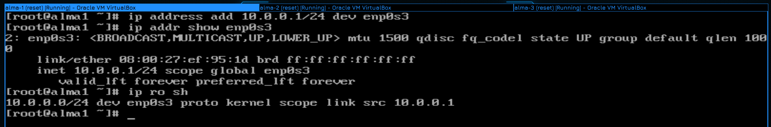
Let’s give each machine a temporary address, network 10.0.0.0 and addresses 1,2,3, respectively:
ip address add 10.0.0.1/24 dev enp0s3
ip address add 10.0.0.2/24 dev enp0s3
ip address add 10.0.0.3/24 dev enp0s3
We set the mask to /24. We will talk about IP addresses another time, so today we will discuss something default. Such a mask tells us that all addresses from 10.0.0.0 to 10.0.0.255 are in our network. We have enough of that. Let’s make sure that the IP address appears on the interface:
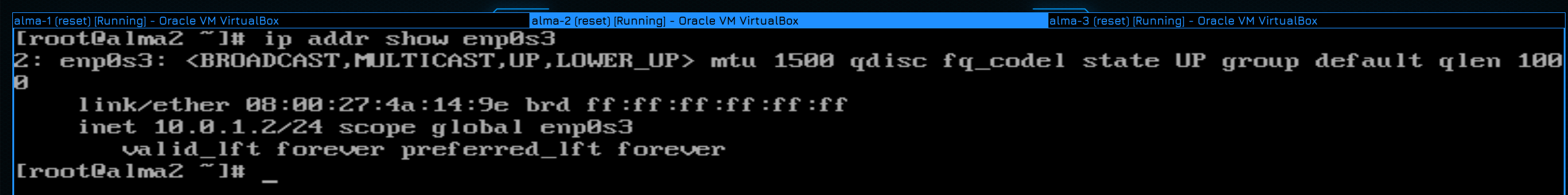
ip addr show enp0s3
As you can see, the address has been registered. Well, let’s check the team’s conclusion:
ip ro sh
Here we can see that any host on the 10.0.0.0/24 network can be connected directly through the enp0s3 interface. Write down the addresses on all three hosts.
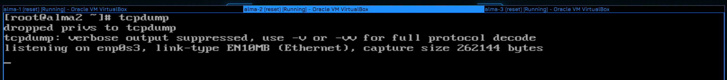
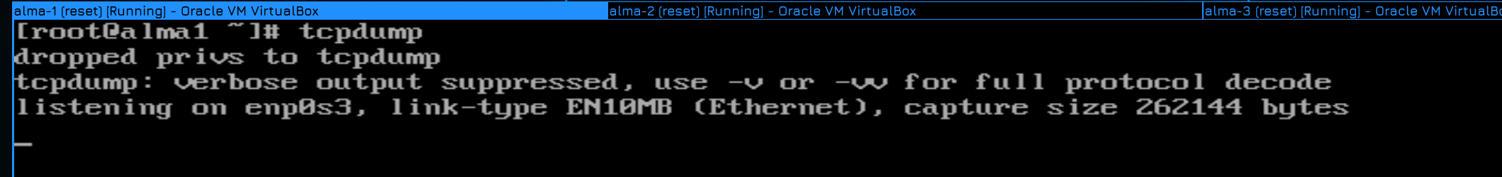
Now run the tcpdump command on the second and third hosts:
tcpdump
It will allow you to see information on all incoming packets.
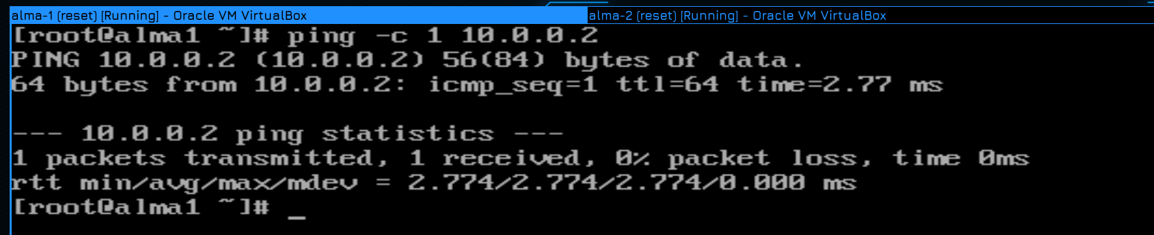
Then we go to the first host and send one ping to the second host:
ping -c 1 10.0.0.2
As you can see, the ping worked, so the network is working.
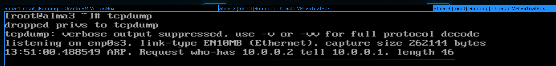
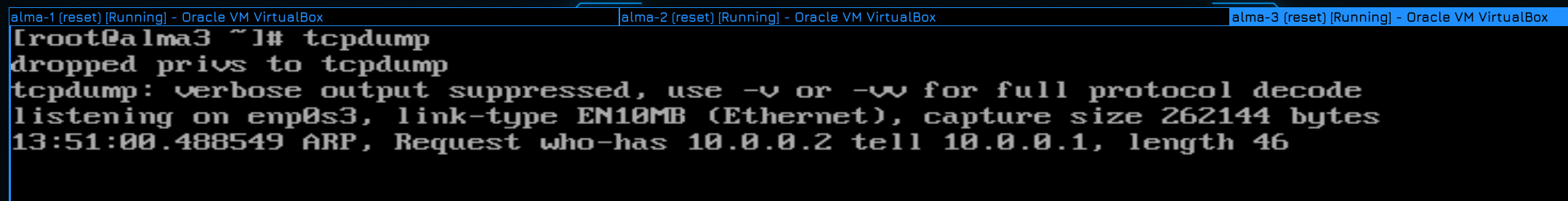
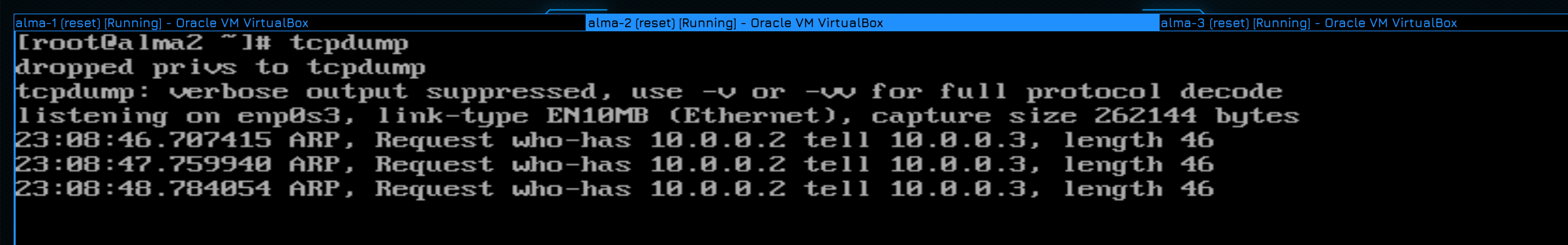
Now we go to view node 3. As you can see, tcpdump issued string-ARP-one request with address 10.0.0.2, response 10.0.0.1. And silence. The fact is that alma1 tried to call the address 10.0.0.2. But it knows only the IP address, and the connection in the L2 network goes by MAC address. So the host has sent a special ARP request – the question is sent to all hosts on the network – say whoever has that IP address, tell me your mac address. This request arrived on the third day and Alma 3 ignored this message because its IP address is incorrect.
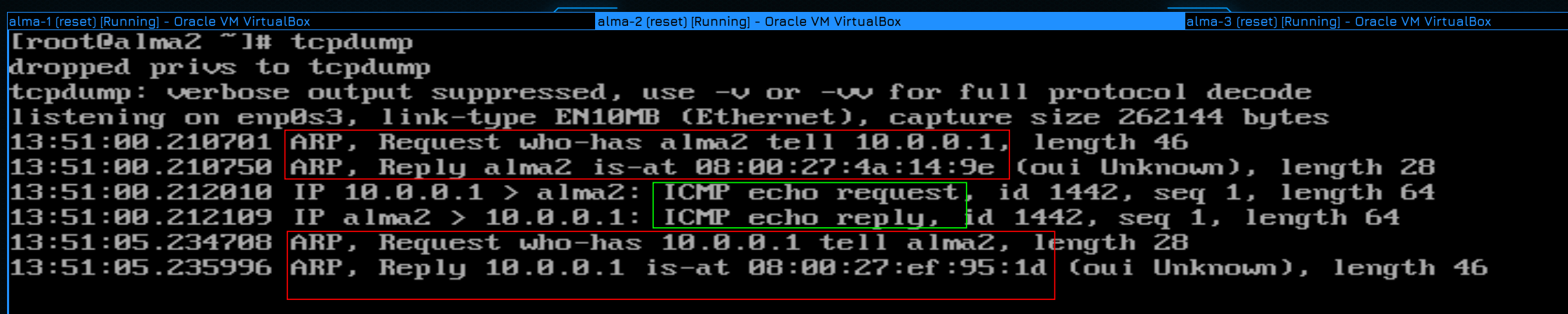
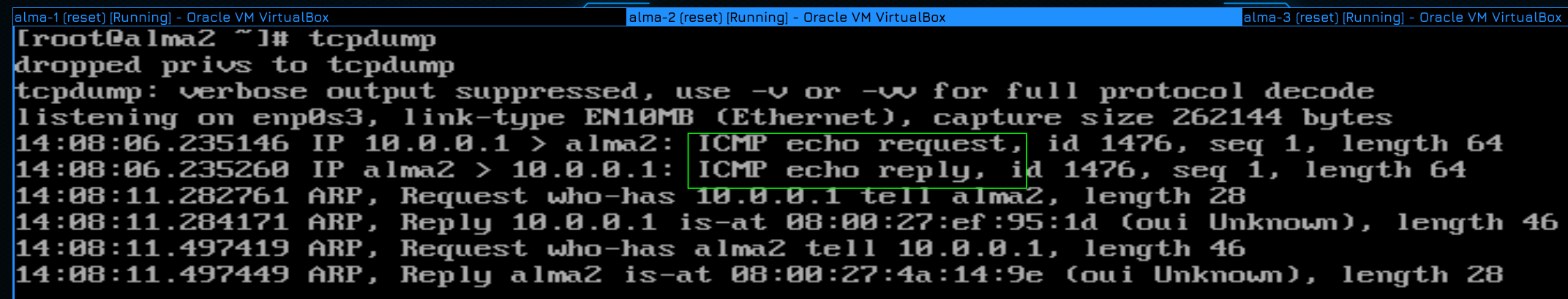
Let’s see what happened on host 2. As you can see, there are already a lot of messages here. At first I see the same ARP request, but now I have a response to it. The response says that such and such address is in such and such mac address. Ignore the word Alma2. The tcpdump utility has converted addresses to names for convenience. Then an ICMP request arrives and there is a ping itself. Next, notice that after a while there was an ARP request again. To bypass the problem, they say, this is not enough, this IP address will be on another computer, the arp table will be updated regularly.
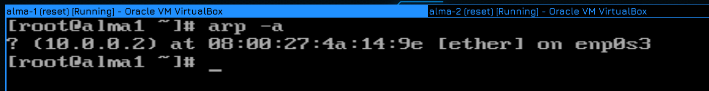
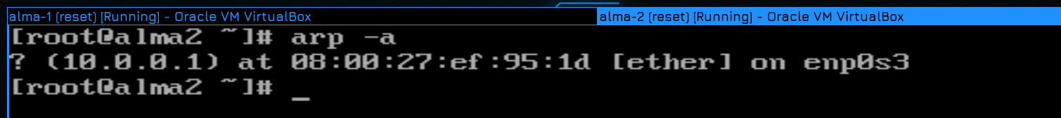
And having done this, both hosts remembered each other by MAC address:
arp -a
And now, if you try the ping again, you can see that the request reached the host immediately.
At the same time, note that on host 3, as there was one request, it remained.
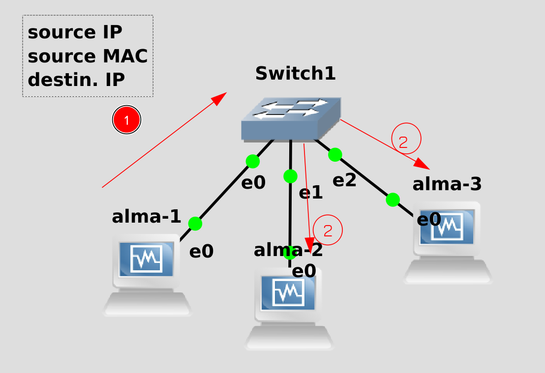
Now let’s try to understand what the role of the switch was. When Alma1 tried to find almu2, it sent a network packet containing alme2’s IP address, MAC address, and IP address. At that time, neither host 1 nor the switch knew the mac addresses of host 2. So host 1 decided to contact all of them – this is called broadcasting. Multilingual request. The switch sent this request to all ports except the source of the request. This entire area from where broadcast requests come from and to which they reach is called the broadcast domain. Roughly speaking, imagine someone screams in 1 room and everyone hears that scream. A shout is a broadcast query and a room is a broadcast domain. As a result, the request went to host 2 and bone 3. At the same time, the switch wrote the original bulk address of host 1 into this table, they say, because there is a MAC address behind port Ethernet0.
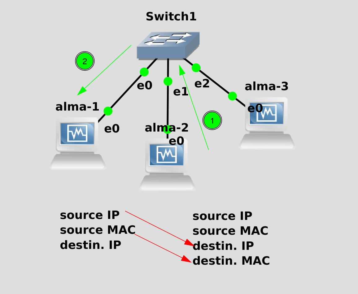
Host 2, having received the request, took the Source IP and Source MAC from the packet, prepared the response and specified them as Destination. I added my IP and MAC to this package and sent it. The switch, seeing this packet, memorized the Source MAC of alma 2, saying that there is such a MAC address behind the Ethernet1 port. The Switch also saw that the Destination MAC address was specified in the packet. And this MAK remembers the switch – it wrote it down in the previous step. Here he immediately sent this packet to the Ethernet0 port.
Now, when these two mac addresses try to transmit something to each other, the switch will immediately send to the necessary ports, while not touching alma3 in any way.
You ask – what’s the point of this? How does this relate to sysadmin? In fact, the main reason why we considered it is to get acquainted with the concept of broadcast domain. The concept of broadcast is used both at the l2 and l3 levels, we are now talking exclusively about l2. And to better understand this, let’s change something in our experiment.
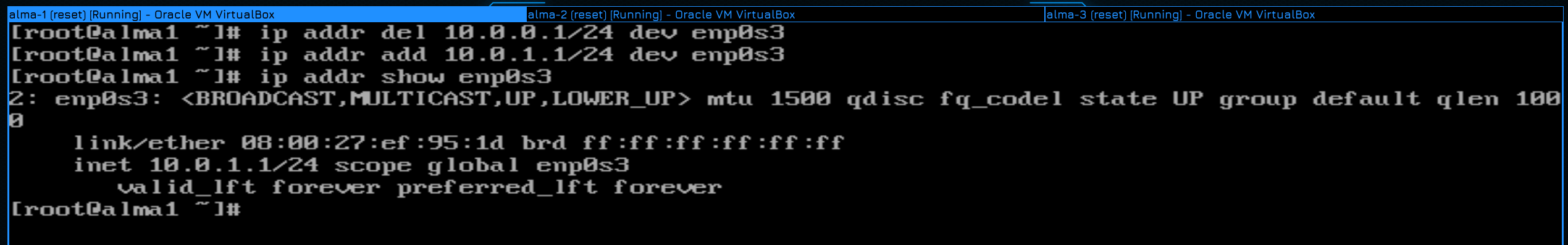
Let’s change the IP addresses of Alma 1 and 2, or rather the network, so that they are now on the 10.0.1.0 network:
ip addr del 10.0.0.1/24 dev enp0s3
ip addr add 10.0.1.1/24 dev enp0s3
ip addr del 10.0.0.2/24 dev enp0s3
ip addr add 10.0.1.2/24 dev enp0s3
And we will leave host 3 on the 10.0.0.0 network. Now, at the L3 level, they are in different networks, and, accordingly, different broadcasts at the L3 level. But at the L2 level… let’s make sure.
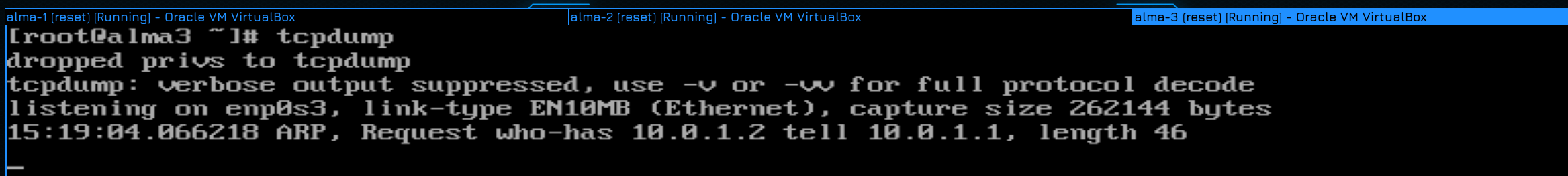
To do this, again, run tcpdump on host 3 and try to ping the second one from the first host:
ping -c 1 10.0.1.2
And as you can see, the third host still received the request even though the network is different. broadcast at the l2 level is general. That is, computers just need to change IP addresses and they will see each other.
Now the question is, why do we need to share the computer on the Network, instead of keeping everything in one shared network? 1 As with virtualization and containers, everything must be isolated. Guests come to your company and they need the Internet. Do they have to be allowed on the same network as the server? Of course not, they don’t have much on laptops and phones. And should the user be connected to the same network? Even if you trust them more, they may simply not know the basic principles of information security. And there is no question of trust in large networks. Some users need access to some resources, others have different resources. There are bosses, Accounting, IT and other departments and they all have different levels of access. Therefore, the network must be partitioned. This is called segmentation. The more you separate everything from each other, the harder it will be to manage everything, but even if there are problems, the losses will be minimal.
As we found out, the distribution simply by different IP networks is not an option at all, computers can still see each other because they are in the same broadcast domain. How to be then?
You can, of course, install a second switch. But it’s like having a separate server for each service – very expensive and pointless. You have 5 people in your department today, 10 tomorrow, 8 the day after tomorrow. You or each department will have to buy a bunch of switches, and if the department is located on different floors and buildings, it’s a total problem. Of course, this is not an option. And here the virtual network – Virtual LAN – VLAN comes to your aid.
VLANs help create different broadcast domains on the same physical network. The device remains connected to the same lamp with 1 cable, but only hosts that are in the same virtual network in the same VLAN are visible. Medium and large companies can have dozens or hundreds of VLANs. And please, only 1 network works in 1 LAN. Say 10.0.0.0/24 on one LAN and 10.0.1.0/24 on another LAN. Each VLAN has its own identifier – this is a general number from 1 to 4094. This identifier is also called a tag and is a kind of label.
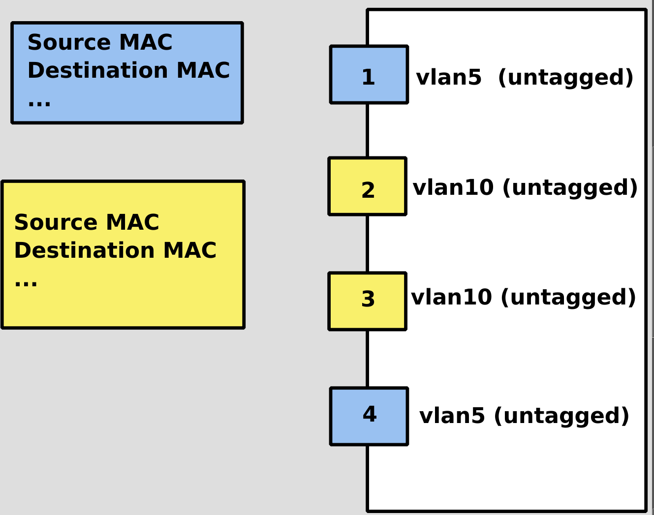
Conventionally, all traffic can be divided into untagged and tagged. Tagged traffic in all packets has a VLAN ID. Usually an unmarked port consists of a switch pointing to a computer – that is. When you connect the cable to the computer, everything works. At the same time, you can specify the port itself on the switch as belonging to a specific VLAN. Conventionally, I want to split the mesh into users and servers, keeping the users in 5 LANs and the servers in 10. Both the user and the server are connected to the same switch, but I know that the user is on port 1 and the server is on port 2. And in the world it is configured that the first port is an unmarked vlan5 port, and the 2nd port is also unmarked, but vlan10 is already there. At the same time, you do not need to configure anything on the user and server computers. The traffic from the first port is shared with port 4. They are in 1 broadcast domain, and ports 2 and 3 are in another 1 broadcast domain.
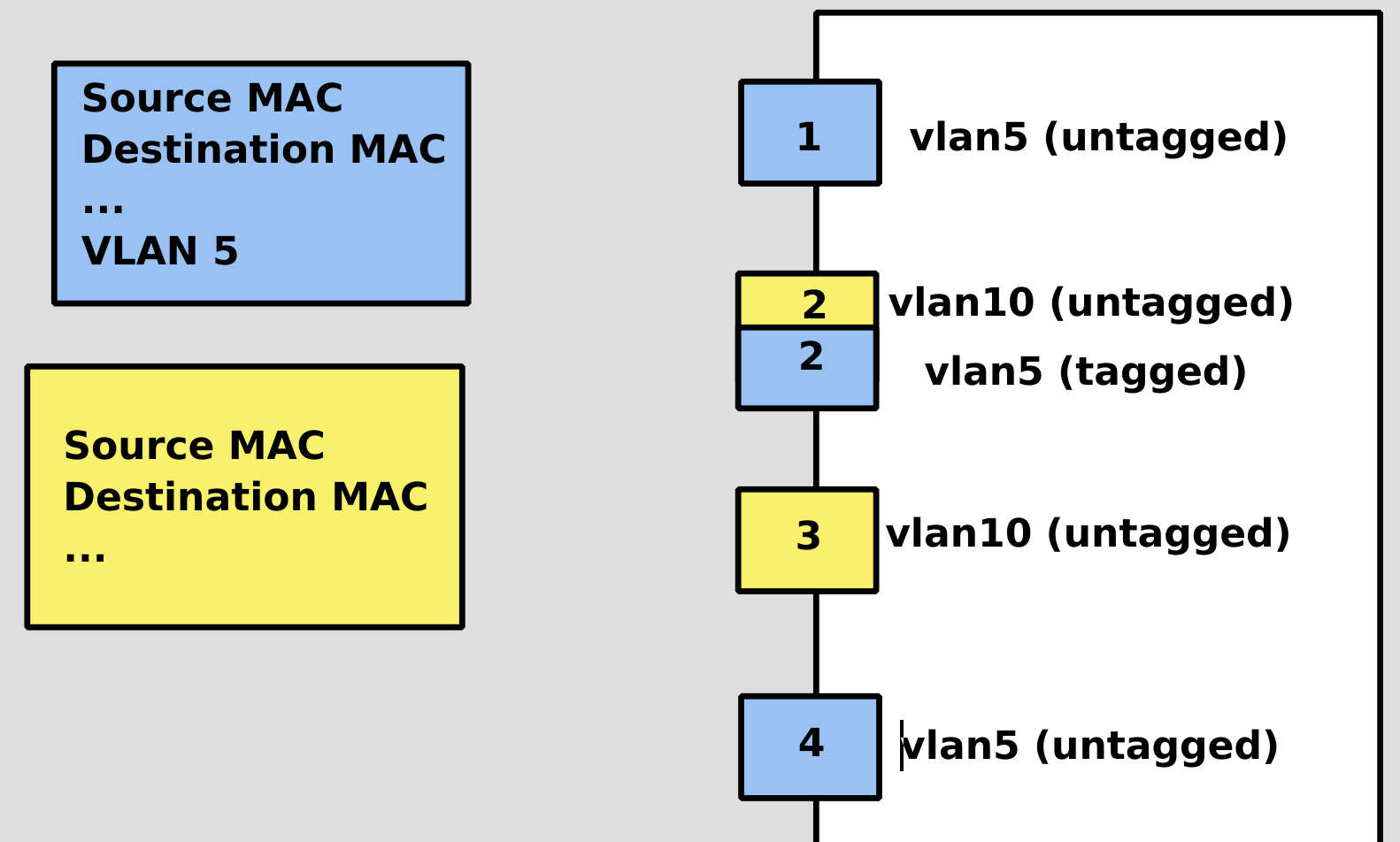
But let’s say I want the server connected to the second port to be in both the user and server domains at the same time. I can either use a separate cable to connect to port 4, or configure port 2 to also have a 5th vlan available. And so that the traffic does not get confused, it is necessary to add VLAN ID to all packets that the server sends to the 5th vlan, and configure the switch to accept vlan 5 in tagged mode on the second port.
As a result, if the server wants to send something to VLAN10, it just sends the packets as usual. Also, if the server wants to send something to the 5th LAN, you need to add a tag to that packet. After receiving a packet with such a label, the switch sends it to one of the ports of Power Source 5. At the same time, when the packet leaves the port without a label, the switch removes the label. The same thing happens in the reverse direction – if the computer on port 1 wants to send something to the server through vlad5, then the traffic reaches the switch in an unmarked form, and the switch marks this packet and sends it to the server in a marked form. If the server looks at the marked package, it will tell you that it is a package from the User’s account. An untagged port is often called an access port. All other LANs must be trained to avoid mixing broadcast domains.
As you understand, distribution most often occurs at the switch level, although not only and often VLANs are configured on the servers themselves. They are general networks – that is. you can create the same VLANs on two different switches, and then computers connected to different switches, but in the same VLAN, will see each other. Naturally, provided that the switches are connected to each other and both of these VLANs are registered.
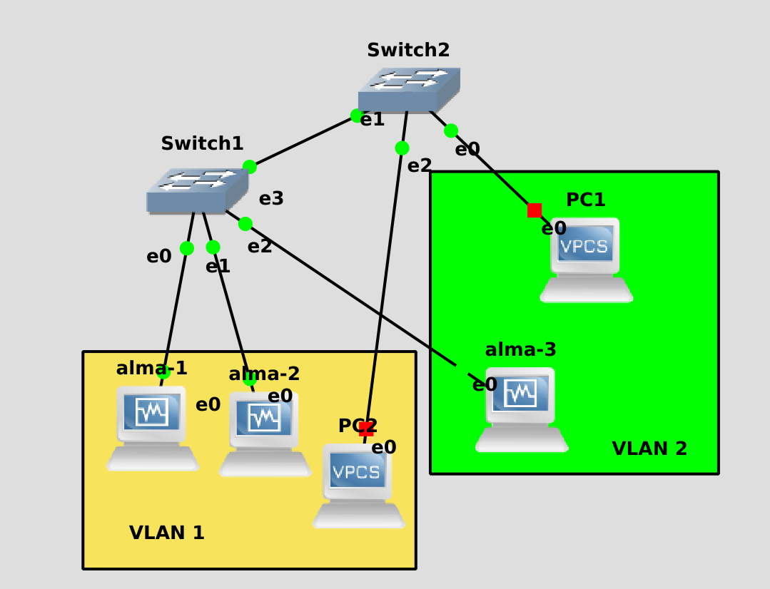
Conditionally, in the drawn scheme there are 2 VLANs – one tag 1, the other 2. In switch 1, vlan 1 is configured on ports e0 and e1, but in port e2 – vlan 2. There is switch 2, which has vlan 2 registered in port e0, but in port e2 – vlan 1. Between the first and second switch there is a cable, which should go through both vlans so that alma3 can see PC1. Alma3 is connected to switch 1, and in order to reach PC1, it needs to get through the first switch to the second. Ports with several LANs are called trunk ports. They are usually made between two switches. But not only.
In many companies, almost the entire infrastructure is built on virtual machines. There are many virtual machines, they are designed for different tasks, and therefore the network between them must be segmented. And often, many LANs are prescribed on the ports of switches that go to servers, and in hypervisors, in the settings of network adapters of virtual machines, you can specify the desired VLAN. As a result, you have virtual machines in different VLANs.
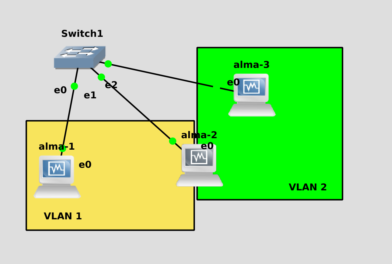
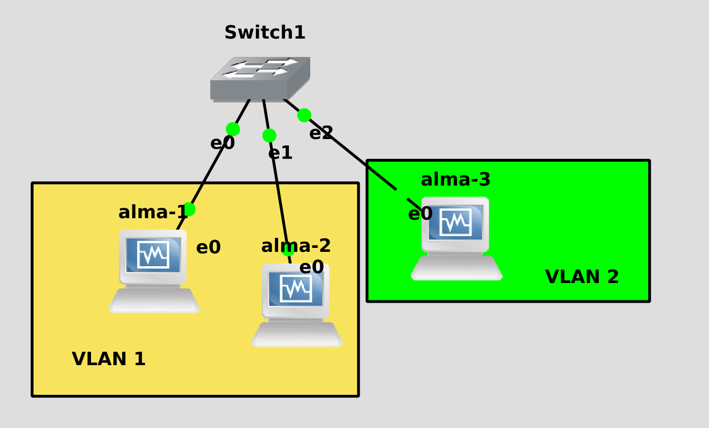
Let’s build such a network, where alma1 is in the first VLAN, alma3 is in the second, and alma2 is both there and there.
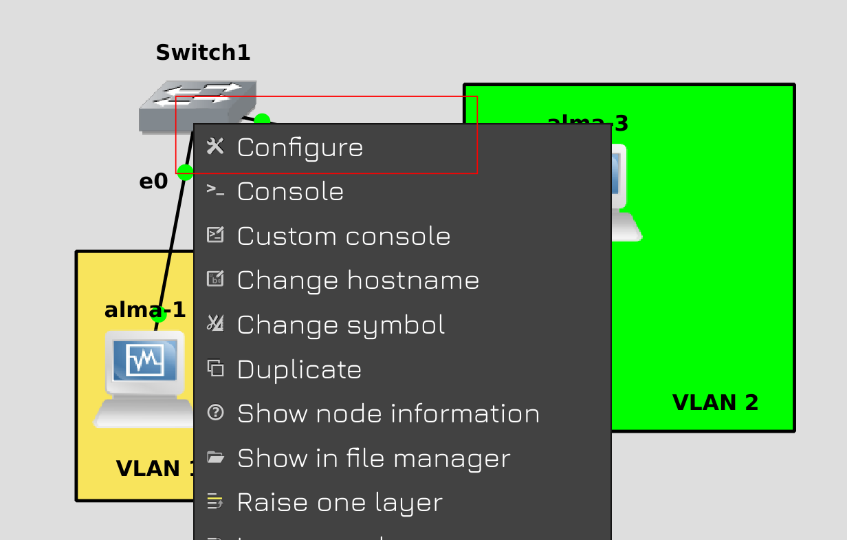
Right-click on the scroll and select Configure.
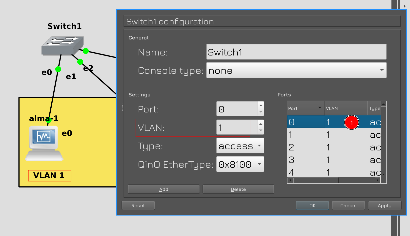
In the window on the right side there will be ports, and on the left you can configure them. Double click on port 0, it is connected to alma1. As you can see, here by default VLAN1 is registered in access mode, i.e. in untagged form. Therefore, we do not touch anything here.
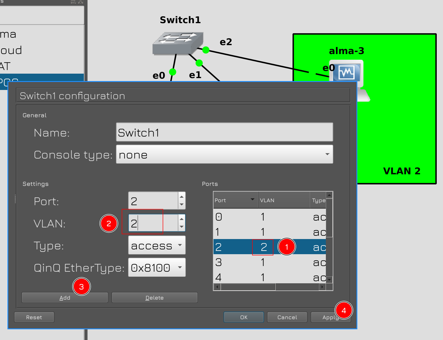
Now for alma3, it is connected to port e2. Double-click the second port. Change the VLAN value to 2, then click Add. Then in the right panel the number will change to 2. Now here it is untagged VLAN 2.
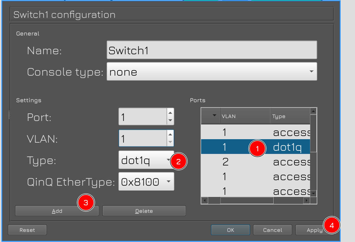
As for alma2, we need to transmit two vlans – vlan1 and vlan2 on the first port. To do this, double-click the first port, do not touch the vlan, but only change the type to dot1q. In the standards, VLANs are specified under the name 802.1q, and dot1q is an abbreviated name. Click Add and Apply.
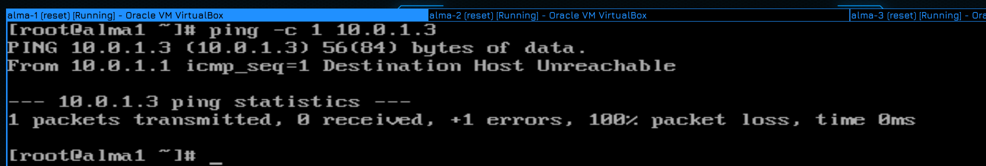
Now, to check if the isolation works, let’s send a ping from host 1 again, but to an unknown IP address, say 10.0.1.3:
ping -c 1 10.0.1.3
There is no host at this address, the computer does not know who to contact, so it will send an ARP request.
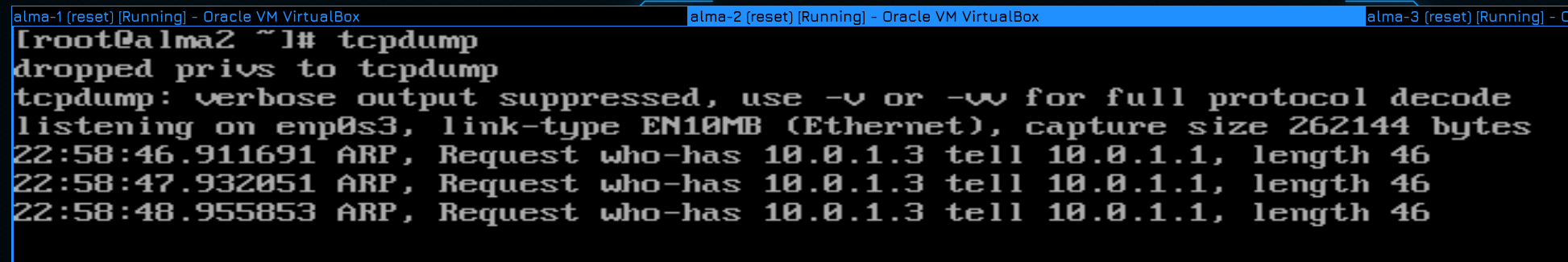
We see this ARP request on host 2. This means that host 1 and host 2 are still in the same broadcast domain as both are connected to LAN 1.
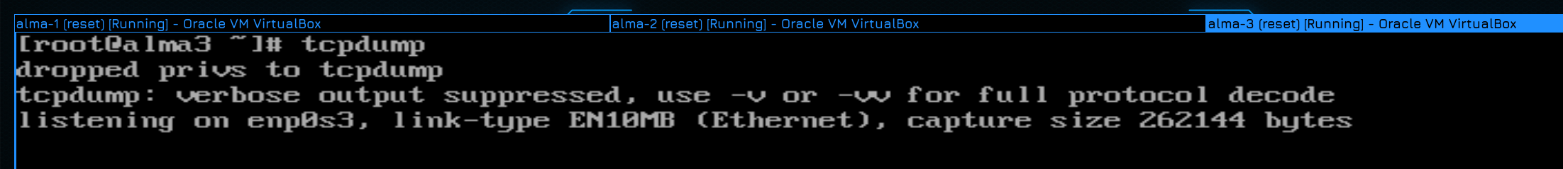
But the request did not reach alma 3, which means that it is not in the same domain as host 1.
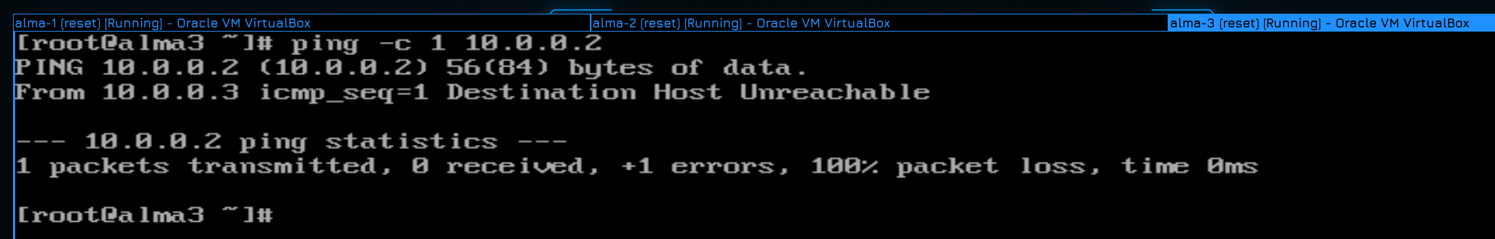
Now let’s check the operation of vlan 2. We ping the address from the third host:
ping -c 1 10.0.0.2
On the first host, as expected, tcpdump is silent – because it is not in the same domain as the third host.
But host 2 sees these requests, i.e. it is in the same doe as host 3.
It remains to configure so that host 2 and three can ping each other, ie. so that the network between them works at the third level. But we cannot simply register a second IP address on the host – the IP address will not be an untagged interface, which means the system will simply reject the packet. We need to create a tagged interface.
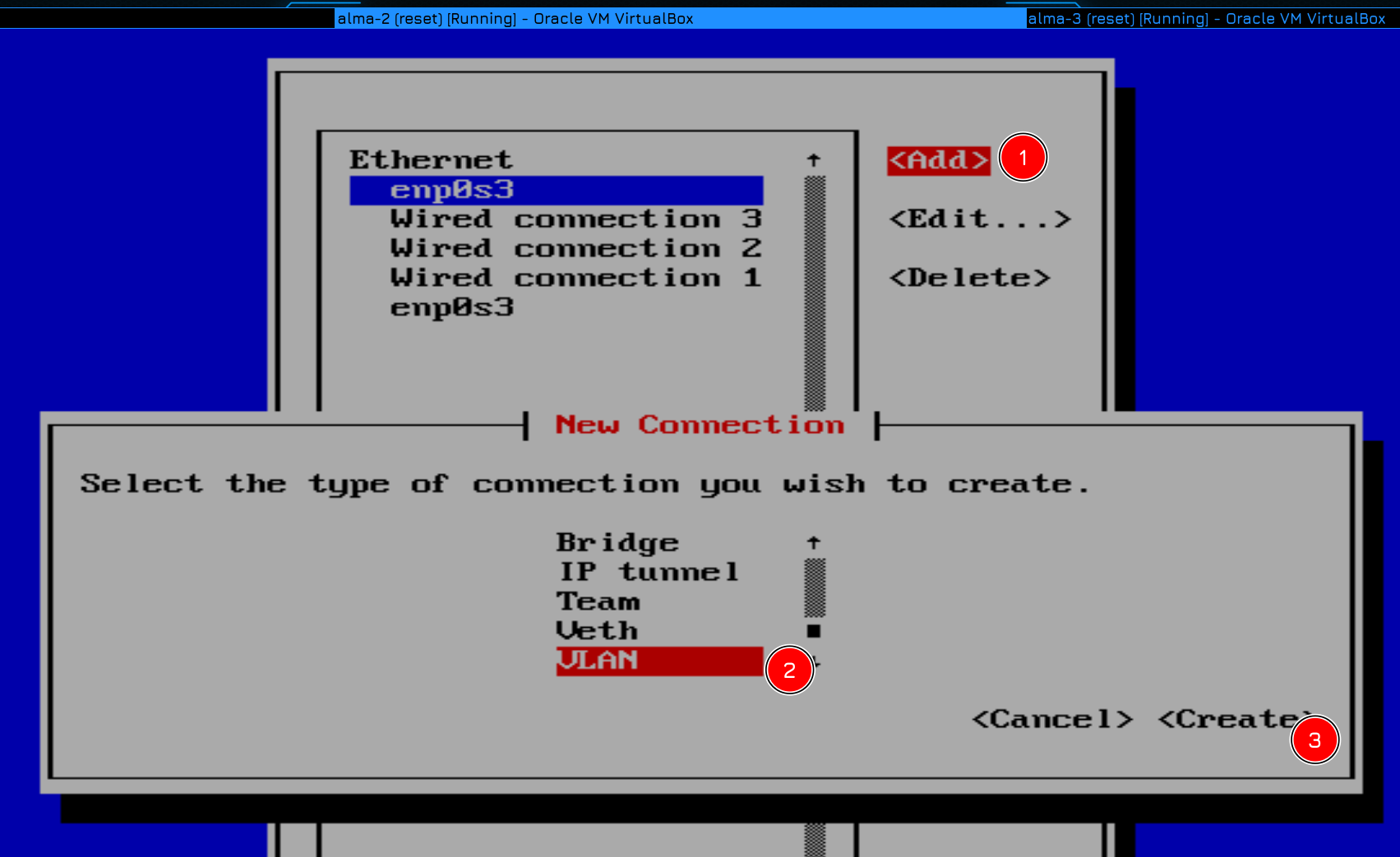
To do this, run nmtui – Edit connection – Add, find VLANs in the list and go to the Create tab.
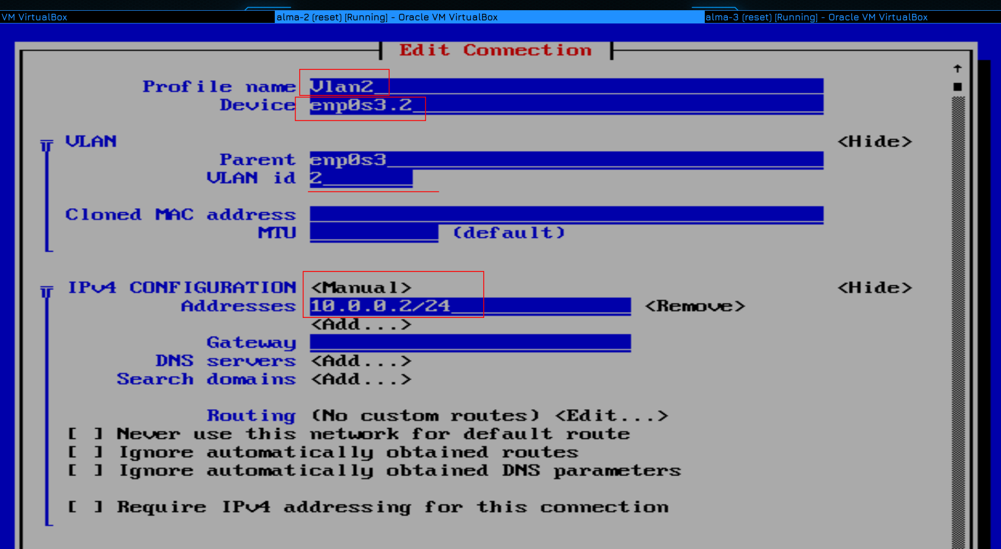
The profile can be named anything, but for clarity let’s call it Vlan2. On the device, write the name of the interface to which the cable with this vlan is connected, then put a period and write the ID VLAN-2. That is, you can see enp0s3.2. When you press Tab, the parent and VLAN id fields are automatically populated from the bottom. Now like the normal interface, I don’t have a DHCP server, so I change the Ipv4 configuration to manual and set the static IP to 10.0.0.2/24. Save nmtui and exit.
Now, after looking at the list of interfaces:
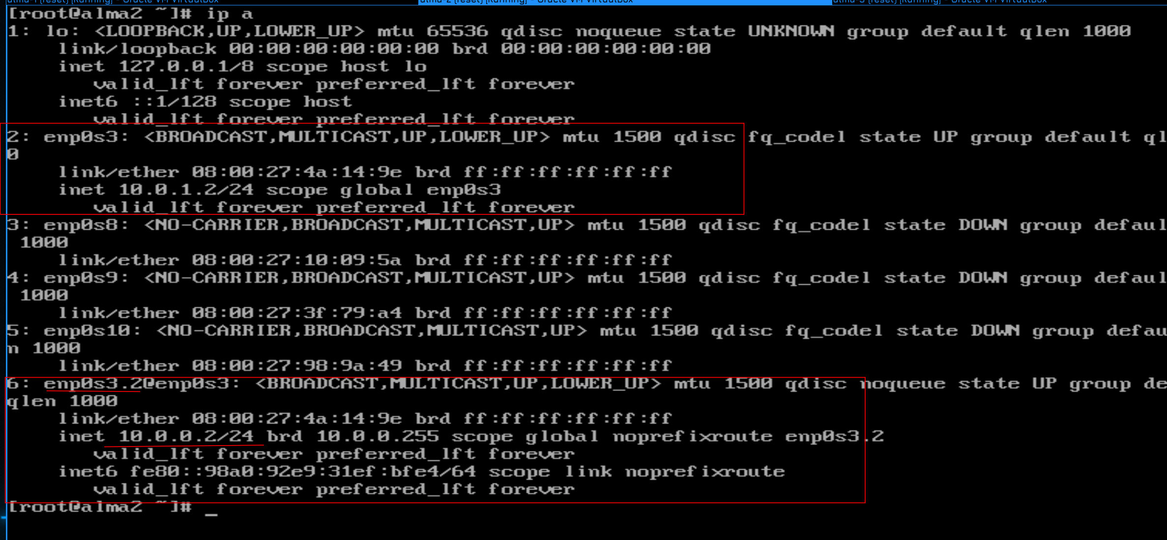
ip a
You can see that a new interface has appeared – enp0s3.2 – and an IP address is written on it.
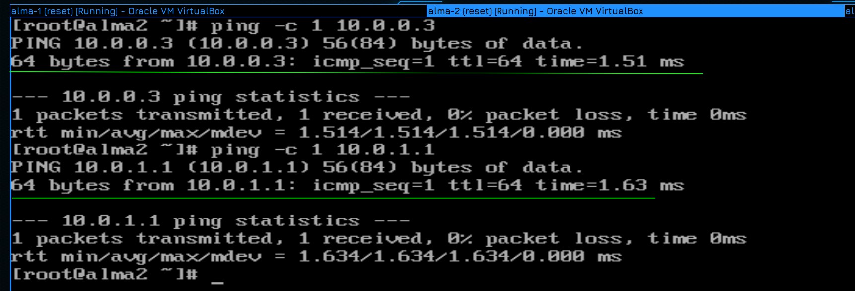
Let’s try to ping hosts 1 and 3:
ping -c 1 10.0.0.3
ping -c 1 10.0.1.1
alma2 reviews both hosting. As we wanted, it resides in 2 different broadcast domains. You can also add a few more to your local network in the same way, but you’re already doing that.
Let’s summarize. Today I took a little apart of L2, talked about the scrolls that live there, got to know the concepts of broadcast, arp, vlan, etc., and also a little bit of shortcuts. We also learned how to register Vlans on the server – this was the main content of this tutorial – to understand why it is needed and how to do it. There are actually other ways, but these are just tools.