
20.03.2024
14 min
3315

It tells about the division of the network into subnets, which allows for more efficient management of users and servers. It includes a description of VLANs (virtual local area networks) and the subnet masks that define the boundaries of these subnets. The role of routers in connecting subnets and the importance of partitioning for network administration and security are also discussed.

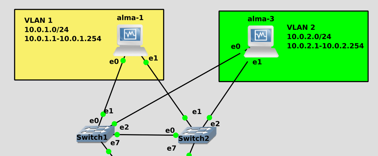
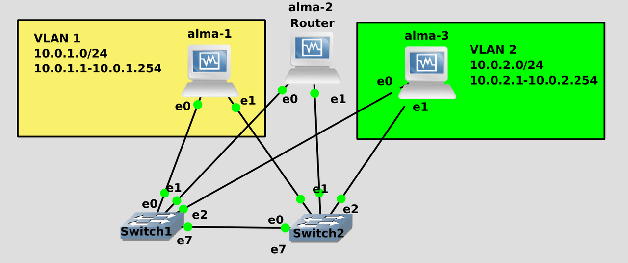
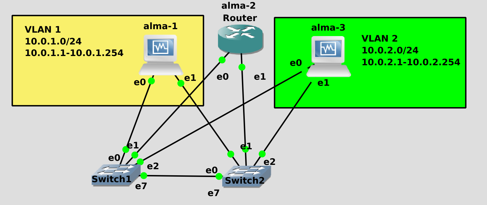
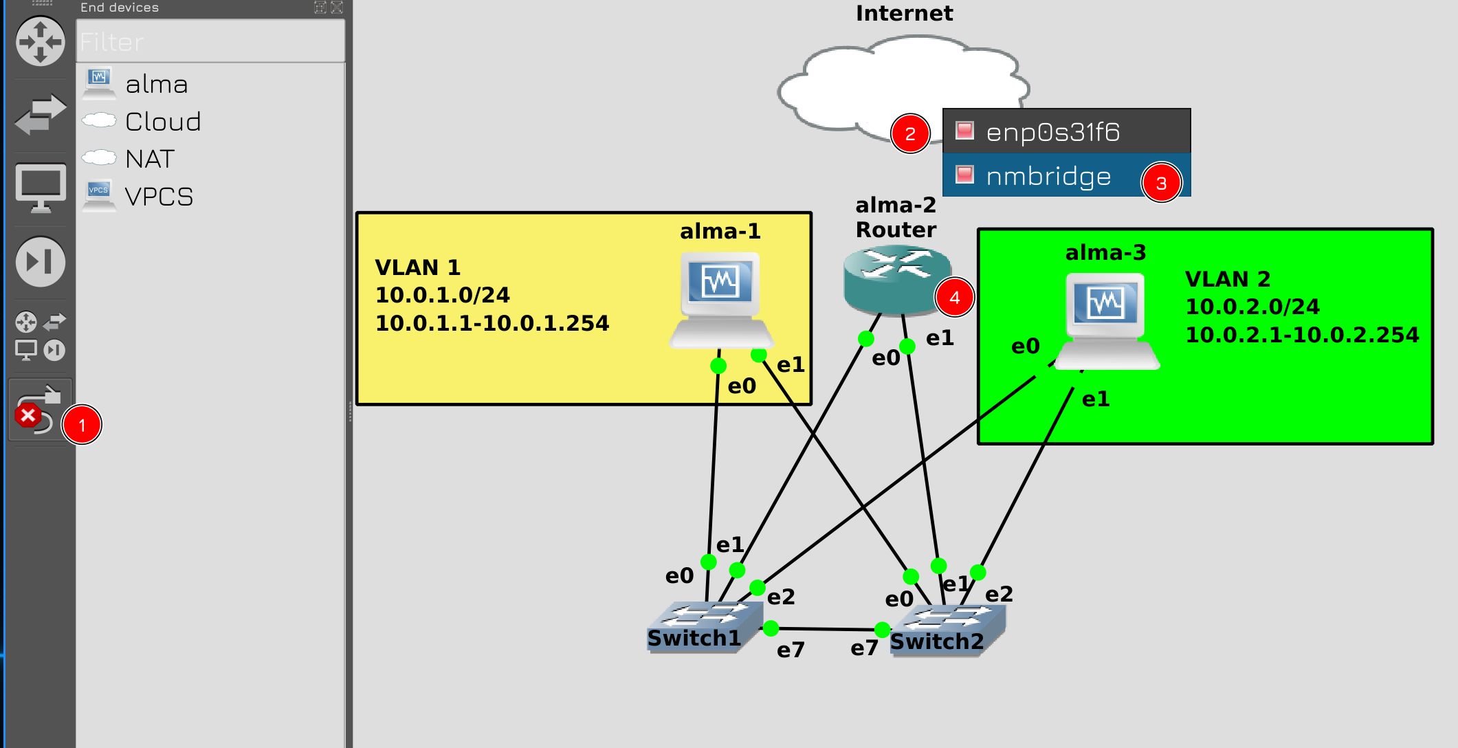
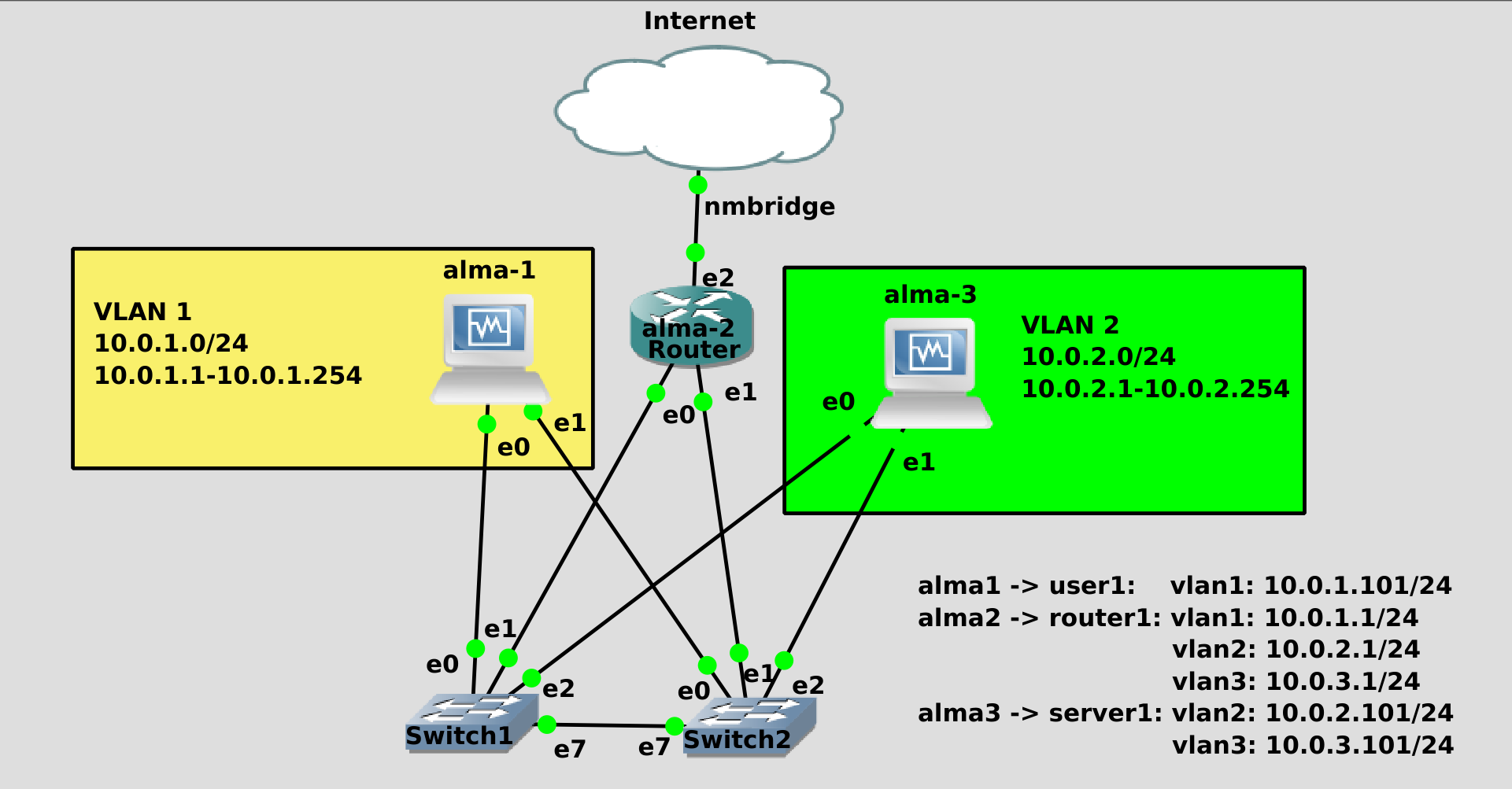
Let’s imagine that we have 2 VLANs in the network – VLAN 1 for users and VLAN 2 for servers. Devices on the same link can see each other directly, using only retinues to connect. It is possible even without switches, simply by connecting two computers with a patch cord. But seeing each other is not enough – the addresses must also be in the same subnet – say, 10.0.1.0/24. Users have IP addresses in the 10.0.1.0 subnet and can vary from 10.0.1.1 to 10.0.1.254. The servers are all the same, but only with the 10.0.2 prefix. Think of VLANs as physical boundaries and subnets as logical boundaries. But what are the logical limits, why exactly from 10.0.1.1 to 10.0.1.254?
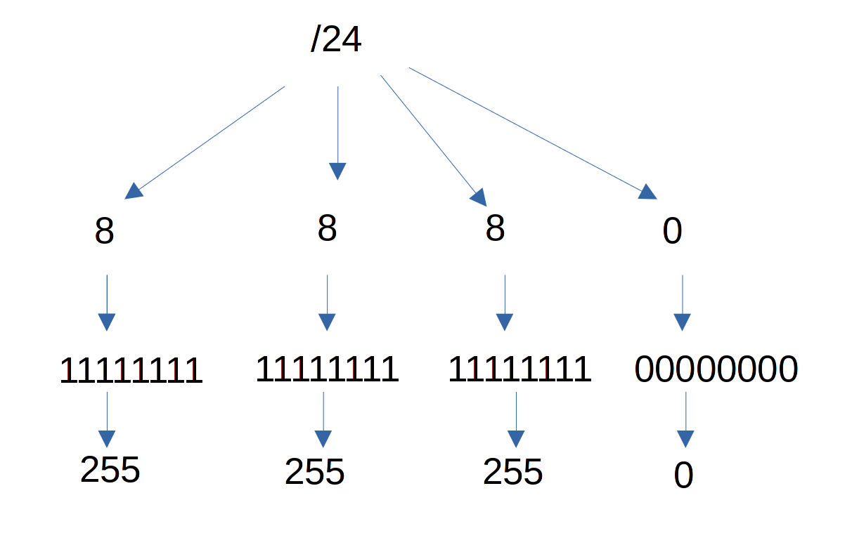
It’s all about the subnet mask, in the same /24 that we specify after the address. I won’t go into too much detail, but in short: in ipv4 everything boils down to 4 bytes, there are 4 bytes for the IP address and 4 bytes for the mask. Each byte consists of 8 bits, which can hold 256 values – from 0 to 255. For example, in the mask /24 – which would otherwise be 255.255.255.0 – the first 3 octets are completely filled, that is. the first 3 bytes, but the last byte is completely free. So, it can take 256 values. This tells us what addresses can be used on that subnet. True, address 0 is allocated as a network address, and address 255 – as a broadcast address. For example, if you send a packet to the address 10.0.1.255, this packet will arrive to all hosts whose address is in the 10.0.1.0/24 subnet.
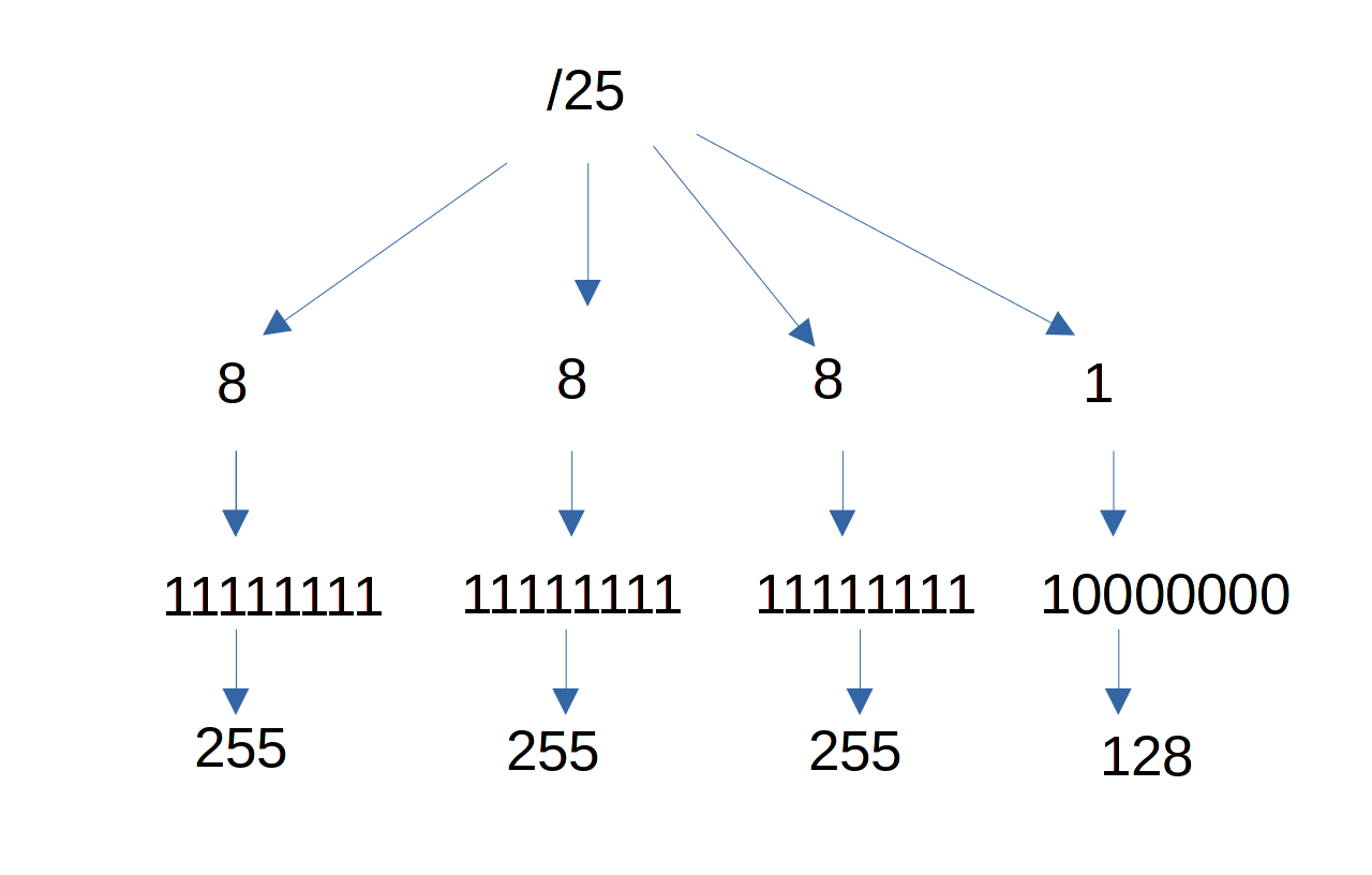
For example, let’s take another mask – /25. In this case, the first bit is jammed in the last octet, so the number of variations is halved – only 128 addresses remain. As a result, the addresses will be from 0 to 127, while 0 will remain the network address, and the broadcast address will become 127. It will be possible to assign addresses from 1 to 126 to devices.
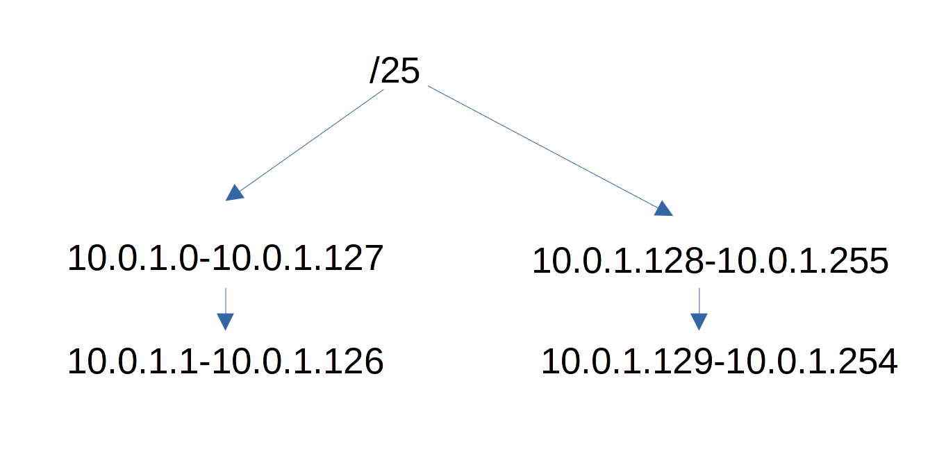
At the same time, due to the fact that we divided the network in half, a second network appears – it starts from 10.0.1.128 to 10.0.1.255. Well, IP addresses will vary from 129 to 254.
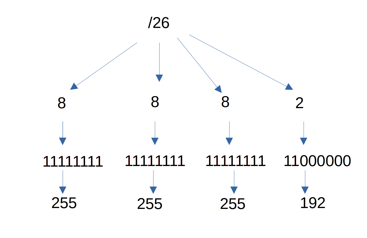
By the same logic /26 – now we will have 64 addresses free.
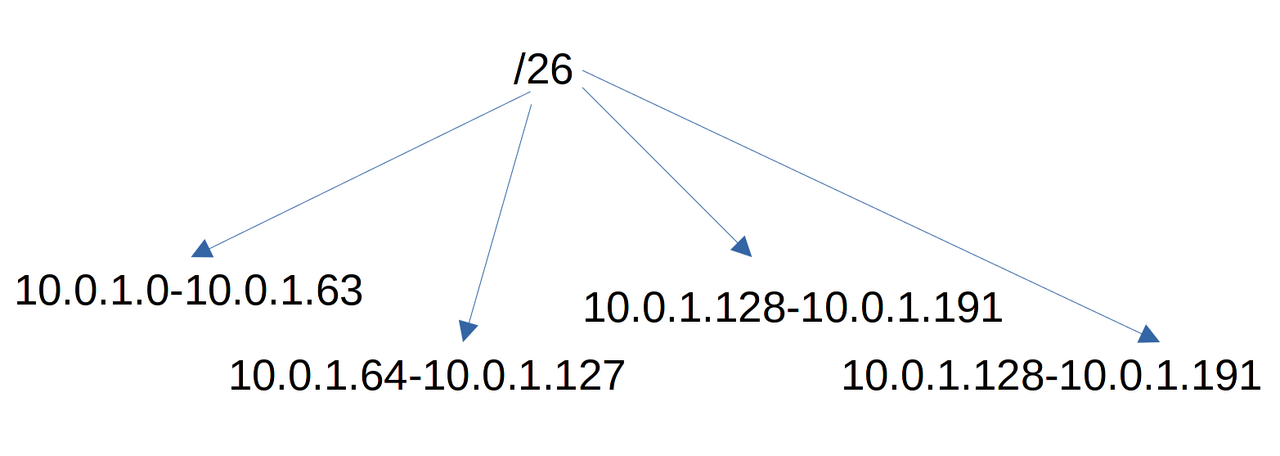
And in this way, 4 networks of 64 addresses will appear, and of course, do not forget about the network address and broadcast, because of which -2 addresses.
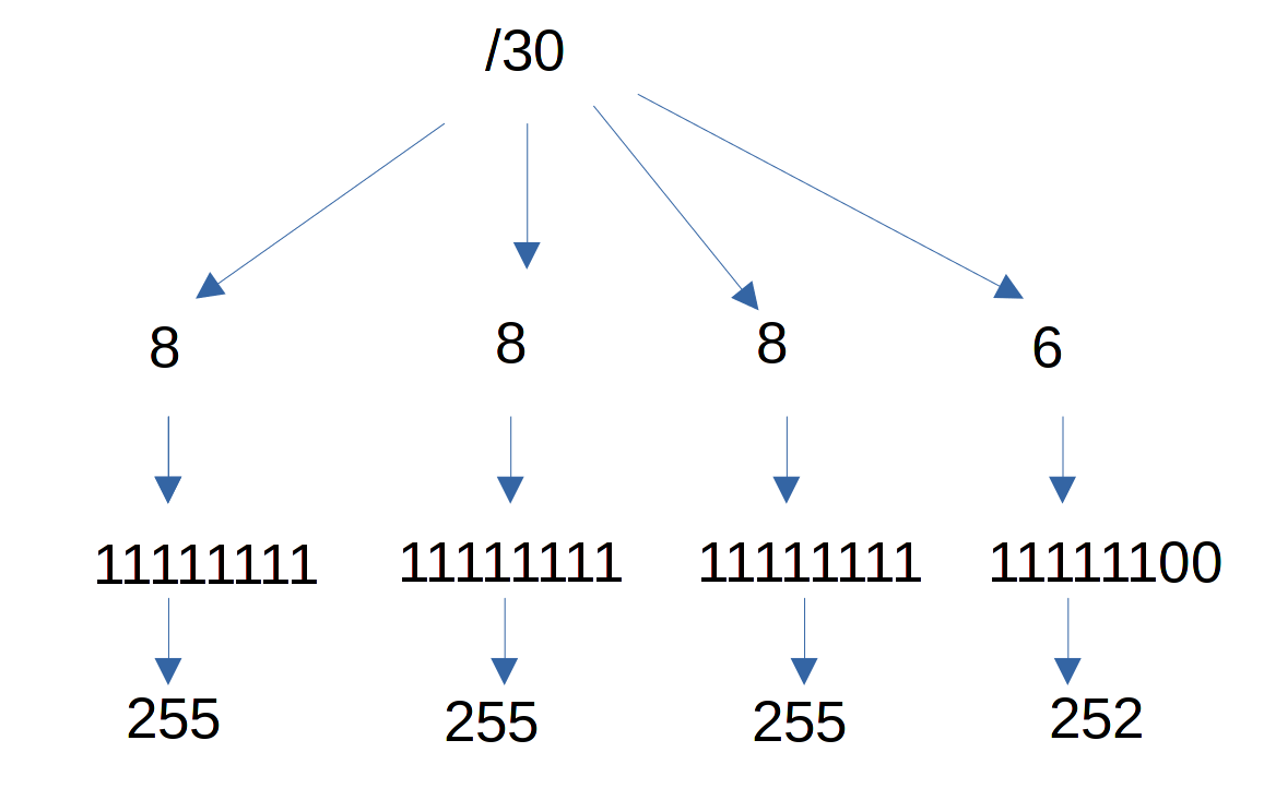
If you rent one public address from a provider, very often the provider allocates a /30 mask to you along with the address – such a grid includes 4 addresses. We take away -2 – we get two addresses. One address will be the address of your router, and the second will be the address of the provider’s router. It’s just that the provider does not want to put all customers on the same network, because it is not very safe. But at the same time, he cannot single out as many as 254 public addresses for you alone. That is why such segmentation is needed – when there are few addresses, but you need to somehow divide them.
If your company does not have tens of thousands of devices, then you can often not bother with masks – there are a huge number of addresses for local networks, so you can hang a /24 mask on each network. Although sometimes you have to divide pods, that is. make several small ones from one large subnet.
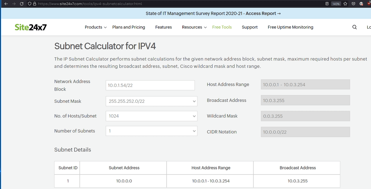
But usually the calculation of subnets, masks and addresses is the task of the network administrator, but the system administrator should have an idea about it. To at least understand that by setting such a mask, such hosts will be in one subnet with him, and such in another. In general, it would be nice to be able to do this just by looking at the mask, but that comes with experience. In any case, there are a huge number of subnet calculators on the Internet – just google subnet calculator. They will allow you to understand what mask to expose, or what hosts are included in your subnet.

And by seeing who is in your subnet, you understand who is not in it. And although we separate, isolate subnets – we still want hosts to be able to communicate. By separating users from servers, we still need users to be able to access servers.
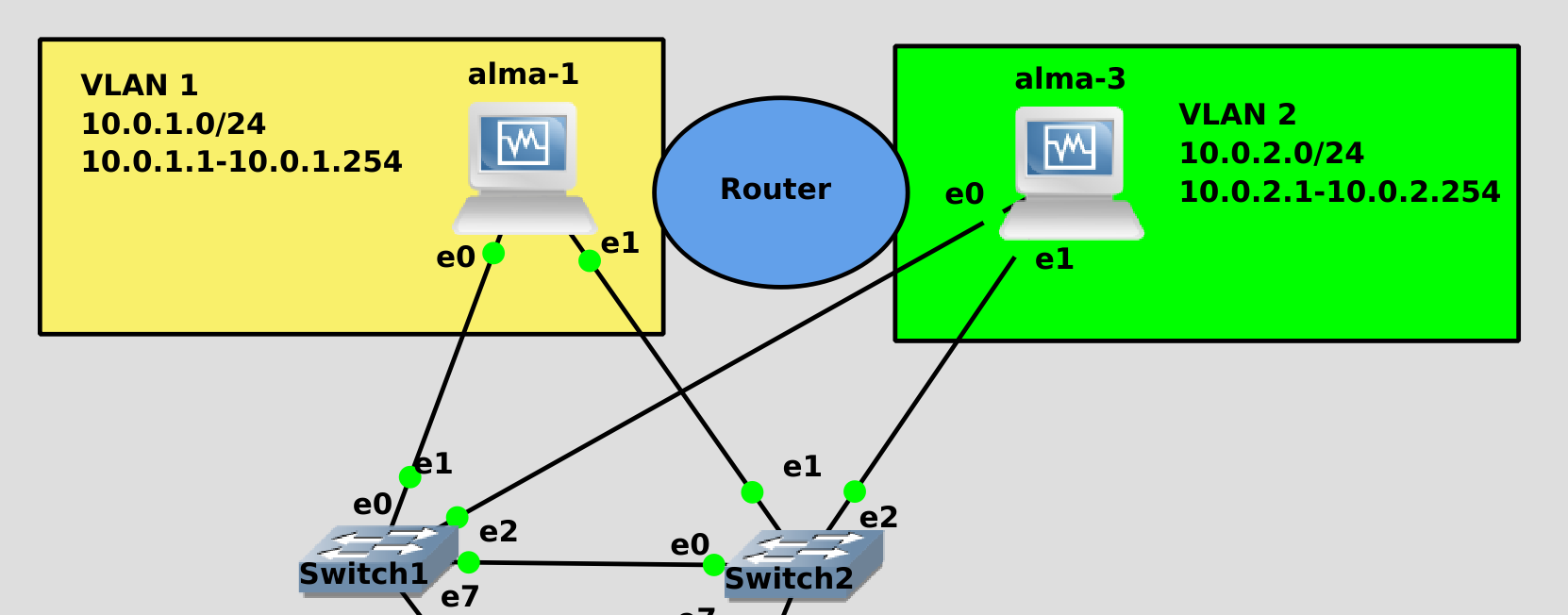
And for this we need a device that will be in the first network and in the second at the same time. If each room is connected to this room, then you need a door that is in both rooms at the same time. And this door acts as a router, or otherwise it is called a router. The main task of a router is to forward packets from one subnet to another. That is, The router resides on level 3 of the OSI model – the network level.
Let’s say alma1 wants to contact alma3. For this, alma1 must understand that alma3’s path leads through the router. And the router must have an address both on the 10.0.1.0 network and on the 10.0.2.0 network. That is, Switches connect devices within the same subnet, and routers connect different subnets, forming a whole network. And by connecting some routers with others, we connect networks, and as a result, all this forms the entire Internet.
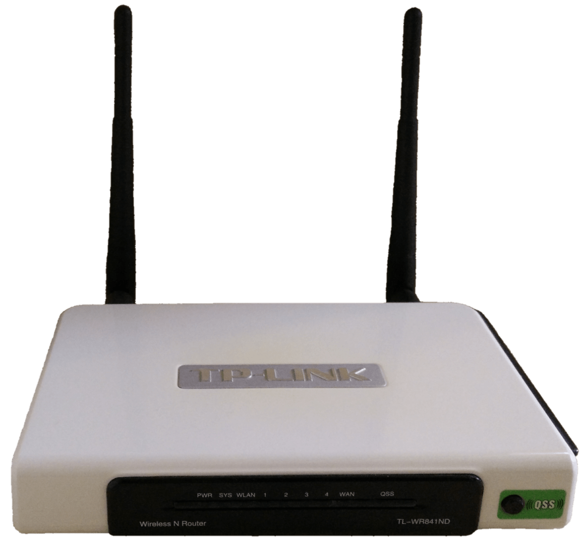
You are all familiar with home routers – a small box with at least 2 ports – one goes to the provider, and the other to your local network.
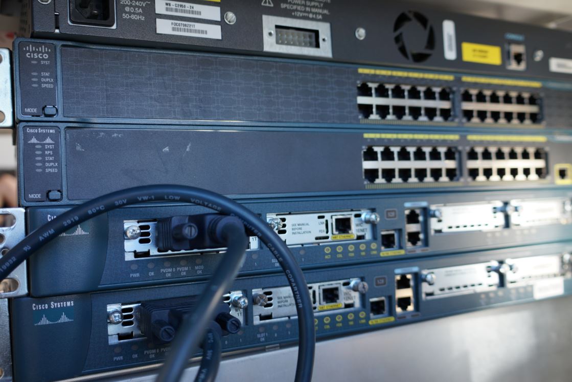
Of course, in medium and large companies there is a lot of traffic and such a box is not enough, so more serious routers are used, which can transmit tens and hundreds of gigabits per second, while they can be mounted in rivers.
Perhaps you asked yourself – why do we need to separate networks, if as a result we connect them through routers? What is the point?
If the router was just a router, then there really would be little point. Not that it was not there at all, at least l2 broadcast traffic does not go through the router, and therefore it would not go from billions of devices and would not overload all the switches in the world. But that’s not what I’m talking about. In today’s world, there is no point in a clean router – it is not enough to simply pass traffic, it must also be checked. Yes, we want users to be able to access servers, but not all of them and not by any protocol. Not every user needs access to the server via ssh, usually access via HTTPS is sufficient. And few of the users need directly to the server with the database.
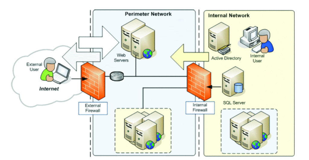
Therefore, routers almost always have a network firewall. It not only passes all traffic, but also checks – can computer 1 access server 1? If not, this package is blocked. But it is not enough to simply check access from one IP to another – maybe we want to allow access on port 80, but block on port 22? So, through the firewall, the router must go beyond l3 – and, at least, think about level 4 – transport, which is responsible for ports.
But this is not even enough for modern routers. Yes, we want the user to be able to access the server on port 80, but what does the user do there? And suddenly he tries to exploit some vulnerability of the web server? Or, say, we allow our user access to the Internet, but we do not want him to go to some dangerous sites? By simply giving him access on port 80 and 443, we will not check in any way which site he goes to.
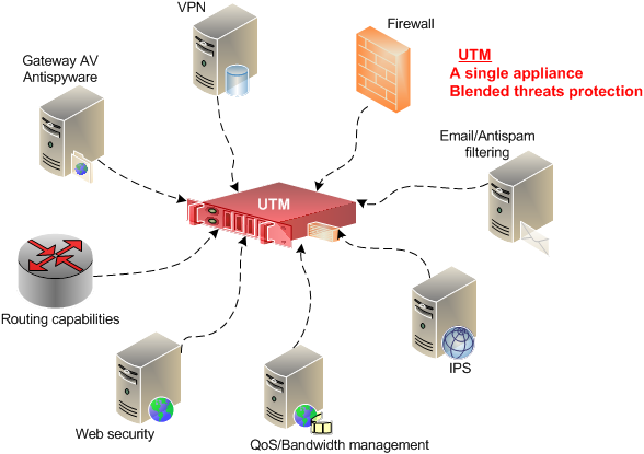
Therefore, simple network firewalls also lost their meaning a long time ago, so-called UTMs are used instead – it is a router, a network firewall, a VPN server, and an antivirus at the same time, and it has a bunch of other security gadgets. This device operates at all network levels for comprehensive infrastructure protection. Naturally, such solutions cost much more than ordinary routers. But if we have already begun to connect what we isolated – then this connection must be safe. However, no matter how multi-functional modern solutions are, the basics of routing remain the same, everything else is gimmicks.
Therefore, first you need to deal with routing. Many modern routers are based on Linux, and we will do the same. Let alma2 be our router.
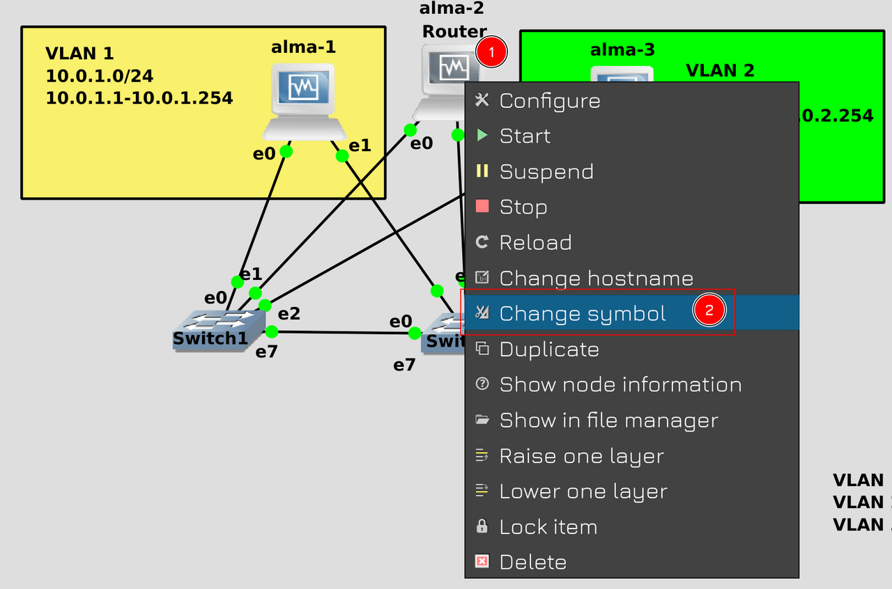
At the same time, for authenticity, we will change its icon to a router. To do this, right-click on alma2 and select “Change symbol”.
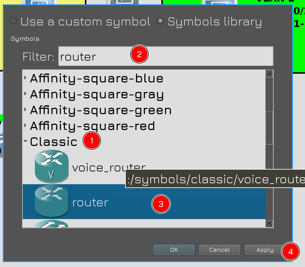
Open Classic and in the Filter field write router. Select the specified symbol and click Apply.

Now alma2 has a router symbol. It remains to do it.
But first you need to prepare the network on the hosts. Last time, on all 3 hosts, we added all 3 vlans, so the hosts will see each other directly:
nmcli con sh
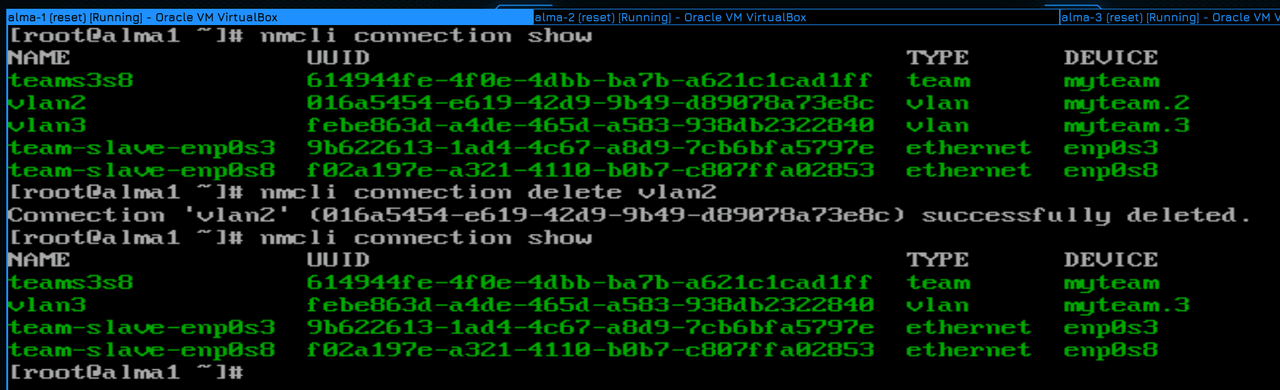
We need host 1 to be only in the first domain – for this we delete vlan 2 from the first host:
nmcli con del vlan2
nmcli con sh
Not everything is so simple on alma3:
nmcli con sh
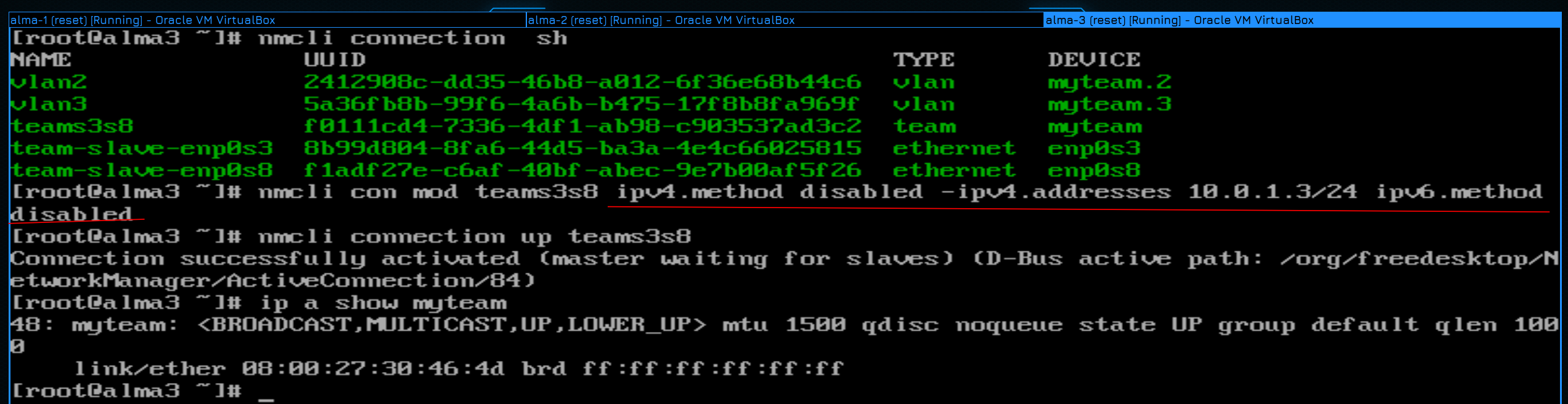
We cannot simply remove the timing interface, because of this, the second LAN will stop working. Therefore, it is necessary to delete the address on the timing interface:
nmcli con mod teams3s8 ipv4.method disabled -ipv4.address 10.0.1.3/24 ipv6.method disabled
At the same time, disabling IP address acquisition on both IPv4 and IPv6, otherwise NetworkManager will overload the interface. After that, you need to apply the settings on the interface and make sure that everything worked:
nmcli con up teams3s8
ip a show myteam
So now alma1 won’t be able to contact alma3 directly because alma1 doesn’t have a 10.0.2.0 network, and alma3 will also be able to answer directly because it doesn’t have a 10.0.1.0 network. They will have to communicate through a router.
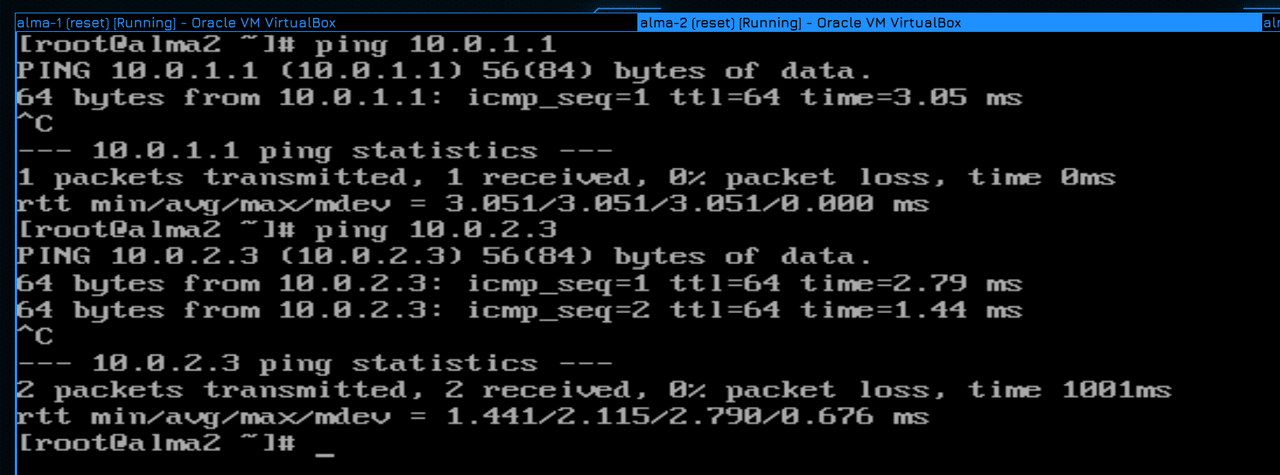
First, make sure that alma2 sees the first host on network 1.0:
ping 10.0.1.1
and the third on network 2.0:
ping 10.0.2.3
Everything is pinged, so the network is ready.
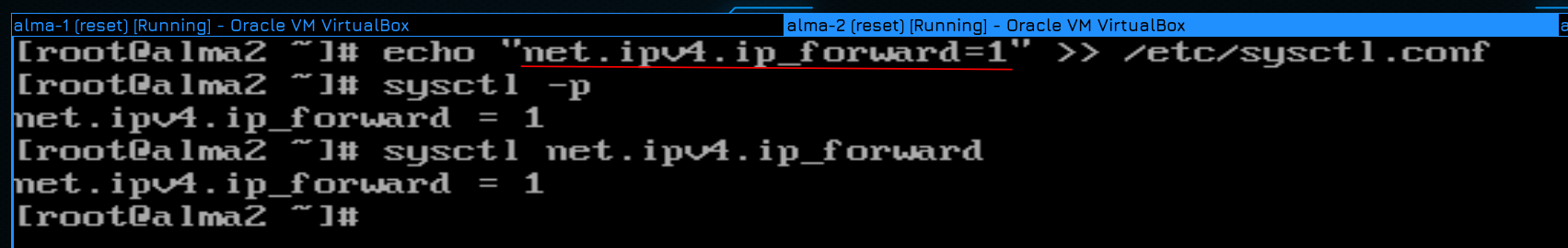
Next, we have to enable routing at the kernel level. This can be done temporarily, but it is better to immediately save it in the settings. For this, you need to add the line net.ipv4.ip_forward=1 in the /etc/sysctl.conf file:
echo "net.ipv4.ip_forward=1" >> /etc/sysctl.conf
After that, we use sysctl with the -p option to apply the settings:
sysctl -p
If everything is fine, you will see a parameter with a new value. And to check at any time whether this option is enabled, you can simply specify it with sysctl:
sysctl net.ipv4.ip_forward
And now alma2 will forward packets from one interface to another.
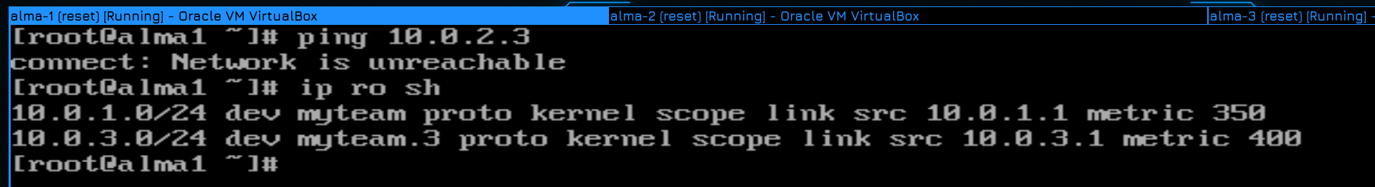
But this is not enough. If we try to ping 10.0.2.3 from alma1:
ping 10.0.2.3
we will see an error – network is unreachable. It’s just that alma1 has no idea how to get to this address. To understand this, let’s look at the routing table:
ip ro sh
As you can see, alma1 only knows about networks 10.0.1.0 and 10.0.3.0.
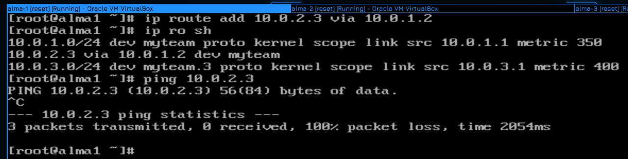
That is, we must tell her that the path to the address 10.0.2.3 lies through alma2, and through the address available to us:
ip route add 10.0.2.3 via 10.0.1.2
ip ro sh
As you can see, we have another route. Shall we try pinging?
ping 10.0.2.3
And there is no answer. Any ideas why that is? Let’s try to figure it out.
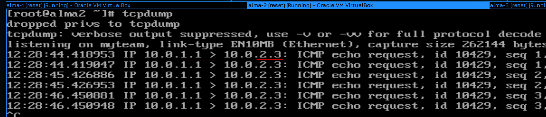
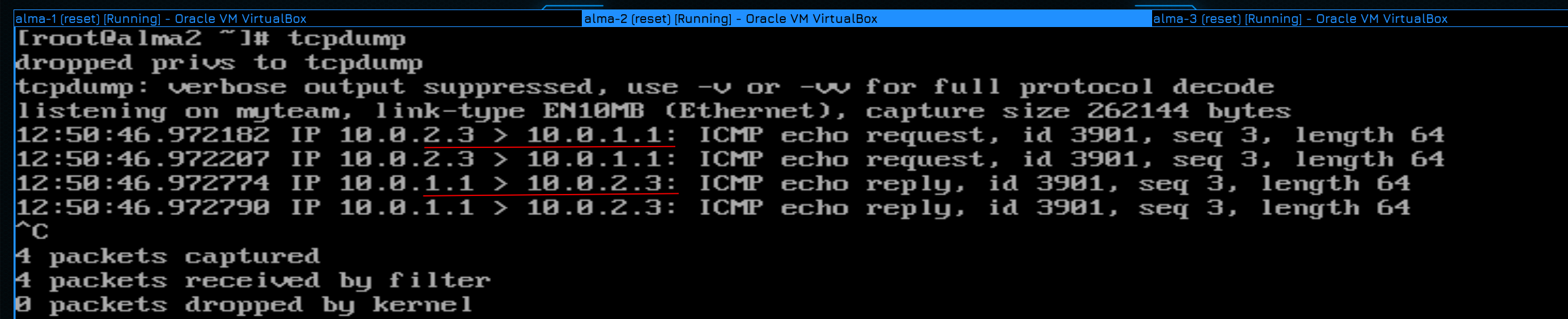
To do this, start ping and go to alma2, where we start tcpdump:
tcpdump
And yes, in the conclusion we can see that packets from alma1 still reach alma2. Moreover, they are redirected to alma3. But we don’t see alma3 sending a response – all packets are coming exclusively from alma1. If there is no answer, then either alma3 does not want to answer, or does not know where to go.
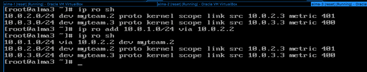
Let’s look at the routing table on alma3:
ip ro sh
alma3 no idea how to answer alma1. Let’s add a route, but this time, not to one specific host, but to the entire network:
ip ro add 10.0.1.0/24 via 10.0.2.2
ip ro sh
Now alma3 will send a packet through 10.0.2.2 to any of the network addresses 10.0.1.0.
And now when trying to ping:
ping 10.0.1.1
everything works.
And tcpdump shows that packets go in both directions.
But we have two subnets. And if there are 5 of them? 10? 100? How many subnets are there on the Internet? Can we register every subnet in the world? Of course not! Instead, we use a special route called a gateway or default gateway. When a computer needs to contact a network where it does not know the route, it sends everything to the gateway. We can specify on hosts instead of all routes that the gateway is alma2. And you won’t need to specify which networks this gateway leads to – just all unknown networks will be sent to alma2 by default.
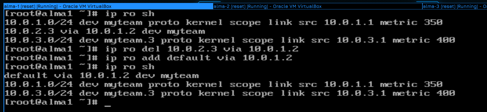
To do this, on the first alma, delete the route leading to the third host:
ip ro sh
ip ro del 10.0.2.3 via 10.0.1.2
Then add the default route:
ip ro add default via 10.0.1.2
ip ro sh
As you can see, the inscription default appeared.
On Alma 3, we also delete the added route:
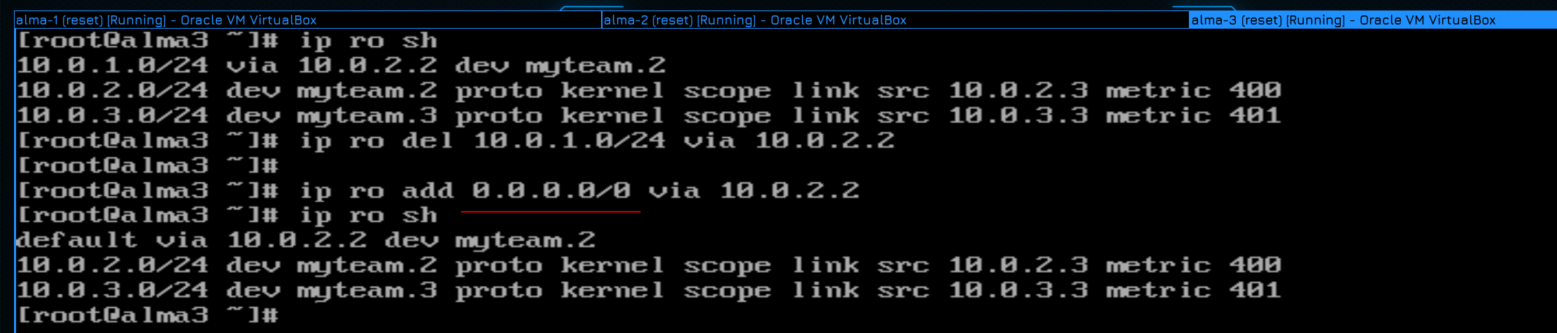
ip ro sh
ip ro del 10.0.1.0/24 via 10.0.2.2
cOn Alma z, also share the add root:
ip ro add 0.0.0.0/0 via 10.0.2.2
ip ro sh
This means any address on any subnet.
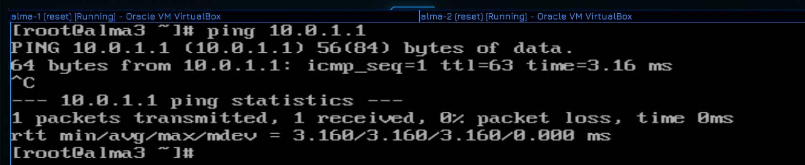
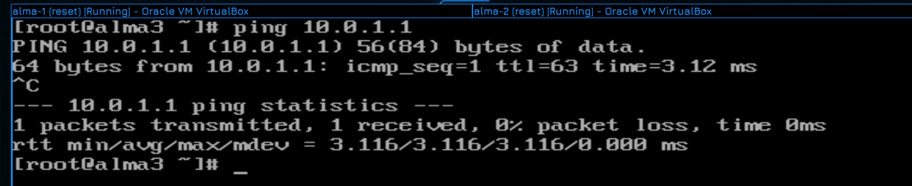
Well, let’s run ping to check:
ping 10.0.1.1
As you can see, everything works.
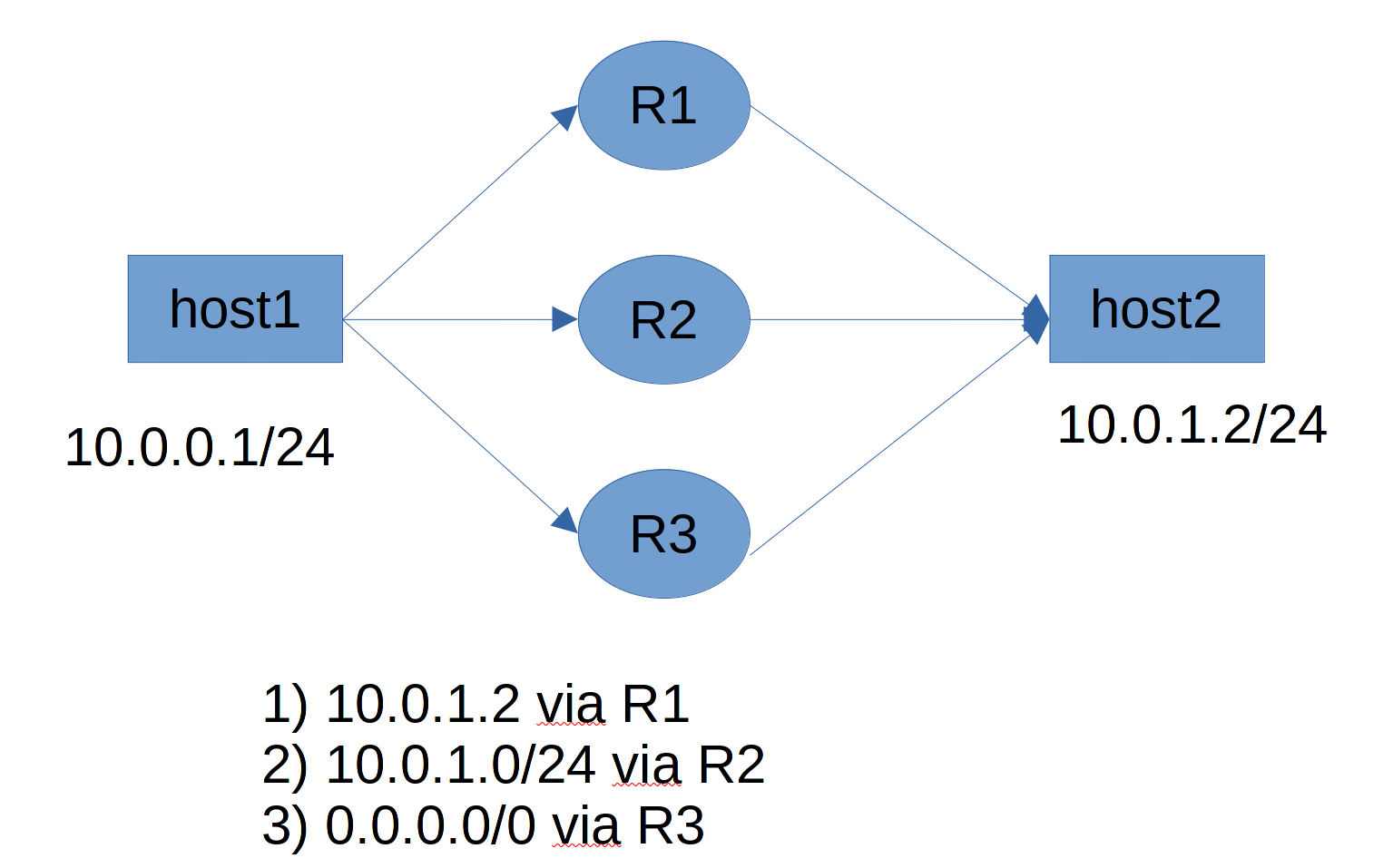
There may be several routes and routers leading to the same hosts. But priority is given to those routes that are more accurate. That is, conditionally, if I specify a route through router 1 to a specific host, through router 2 to an entire subnet, and specify router 3 as a gateway, then the route through router 2 will be used when contacting the host.
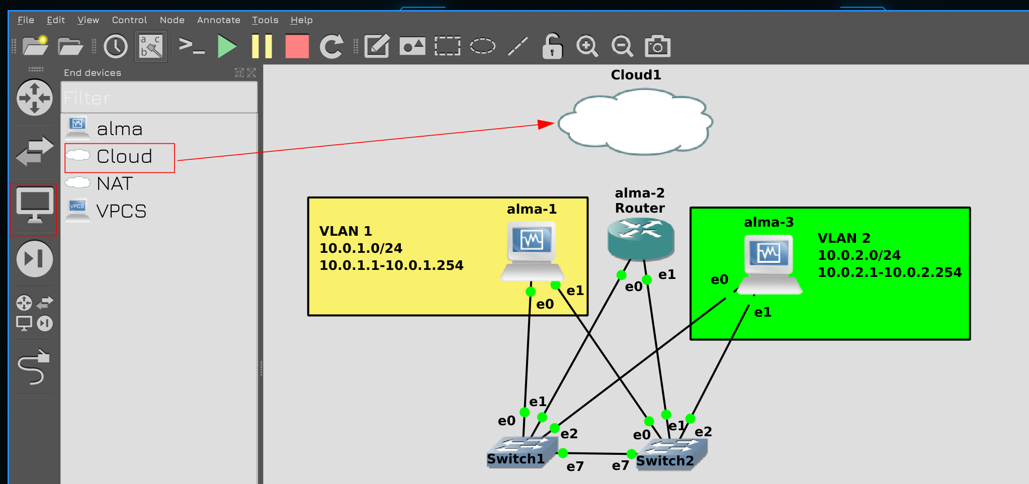
Now let’s connect our scheme to the Internet. To do this, click GNS on the monitor icon in the left panel, select Cloud and drag to the center.
Then connect the cloud to the router using a cable. The cloud represents your computer, and as we in VirtualBox chose the adapter for the network bridge, here too you need to choose the adapter of the computer connected to the network. On the alma2 side, select 3 ports.
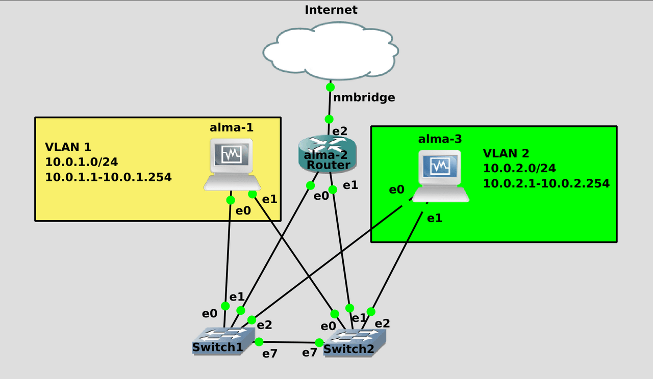
As a result, you will get such a scheme. Here we have a local network consisting of 3 virtual machines. One of the virtual machines acts as a router and will be connected to the local network inside GNS, as well as to the home network.
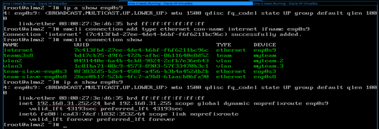
Since we connected the wire to the third port on alma2, the enp0s9 interface will go up:
ip a show enp0s9
We will need to create a new profile in NetworkManager:
nmcli con add type ethernet con-name internet ifname enp0s9
nmcli con sh
We choose ethernet as the type, because it is not a vlan and not a timing interface, but we specify enp0s9 as the interface. It is not necessary to specify the IP address, because our home router will give it an address via DHCP:
ip a show enp0s9
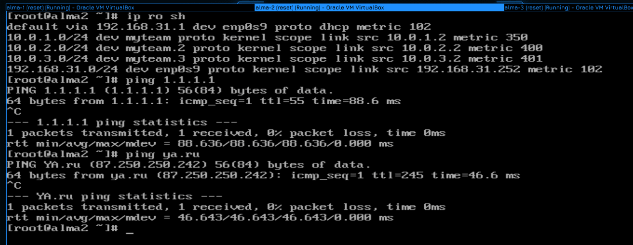
At the same time, we also get the default gateway from DHCP:
ip ro sh
It is our home router. Well, let’s make sure that the Internet is available, with ping 1.1.1.1 and ya.ru:
ping 1.1.1.1
ping ya.ru
Everything is pinged.
Now let’s fix the routes on alma1 and alma3. We specified them using the ip command, so these settings will fly. We need to specify the gateway in the NetworkManager profile:
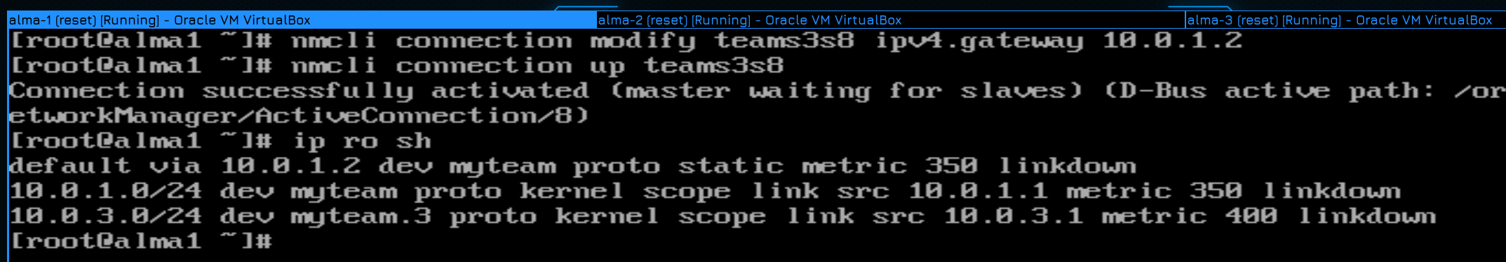
nmcli con mod teams3s8 ipv4.gateway 10.0.1.2
After that, raise the profile again and check:
nmcli con up teams3s8
ip ro sh
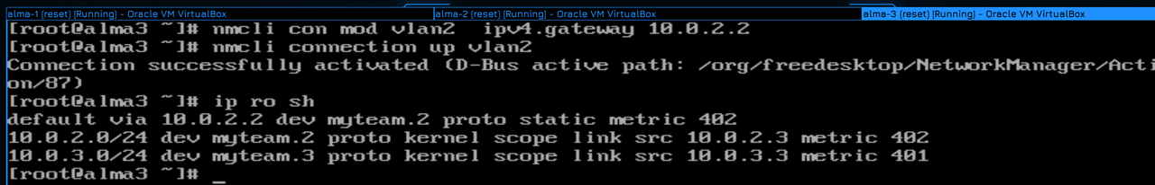
We do the same on alma3, change the profile:
nmcli con mod vlan2 ipv4.gateway 10.0.2.2
Then we raise the interface and check the routes:
nmcli con up vlan2
ip ro sh
Everything as we wanted.
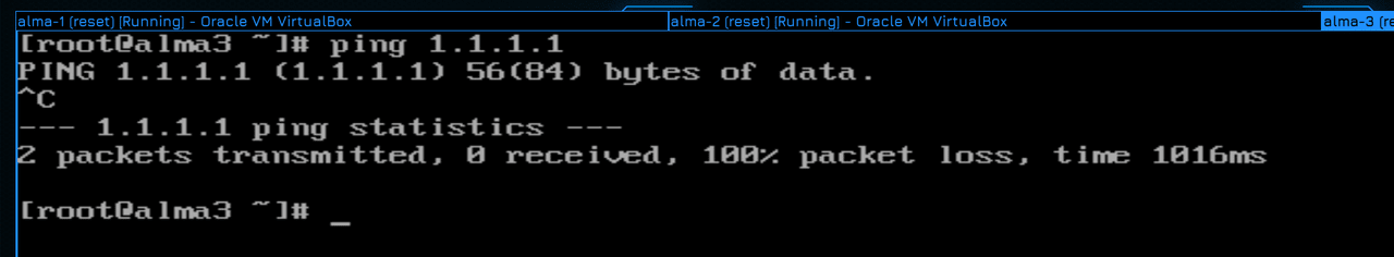
Do you think the Internet will work on these hosts? Let’s check:
ping 1.1.1.1
As you can see, it does not ping. At the same time, there is no network unreachable error – we have a gateway, which means we know where to go, who to look for this address. But then why is it not pinged?
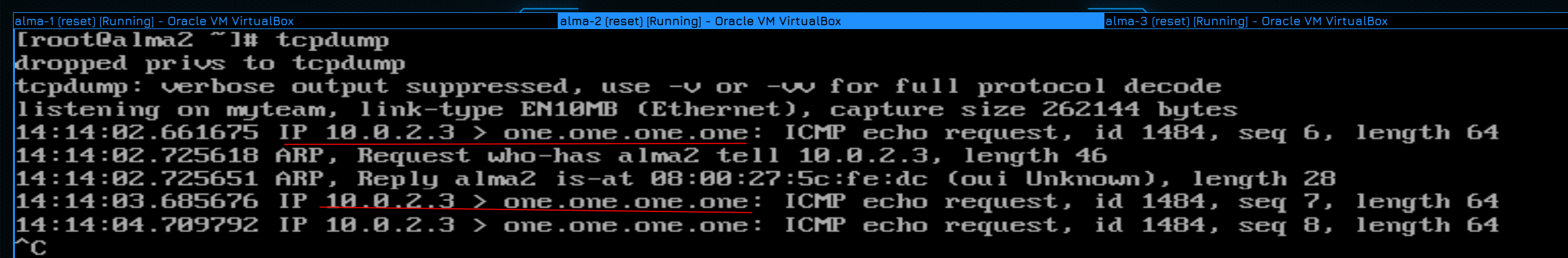
Remember the problem when we first tried to ping alma1 from alma3? Let’s ping and see a tcpdump on alma2:
tcpdump
Does the error remind you of anything? The packet goes from host 3 to 1.1.1.1, but there are no responses. What did it have to do with last time? That’s right, the other host didn’t know the return route, we needed to write the route to alma1 on alma3.
But can we register a route to our virtual machine on server 1.1.1.1? Of course not, between our virtual machine and this server there are a dozen different routers that are owned by different providers. Each of these providers can have their own network with the address 10.0.2.3, because this is an address allocated for private use. How then does our home computer see the Internet? That’s right, our router hangs its address on outgoing packets, replacing the address of our computer. And it’s called NAT.
And we, according to the same principle, should apply NAT to alma2 on the outgoing interface, i.e. replace the addresses of all outgoing packets with the address of the enp0s9 alma2 interface.
Usually the firewall is responsible for NAT:
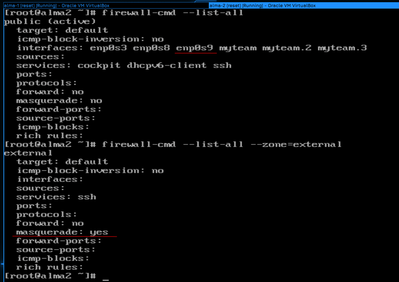
firewall-cmd --list-all
Our enp0s9 interface is now in the public zone. We ideally need a separate zone for the external network so that outgoing packets from that zone are clicked. And there is such a zone – external:
firewall-cmd --list-all --zone=external
As you can see, in this zone, the masquerade option is set to yes, which is exactly what we need for NAT.
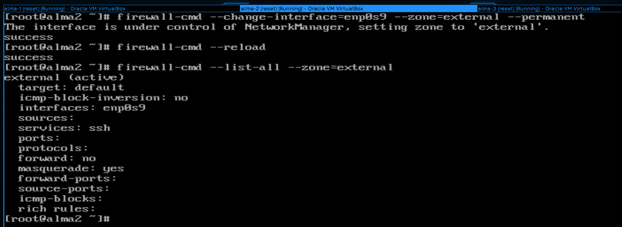
Therefore, all that remains for us is to change the zone for the enp0s9 interface:
firewall-cmd --change-interface=enp0s9 --zone=external --permanent
After that, do not forget to re-read the firewall settings and make sure that everything was applied:
firewall-cmd --reload
firewall-cmd --list-all --zone=external
As you can see, enp0s9 is now in the external zone.
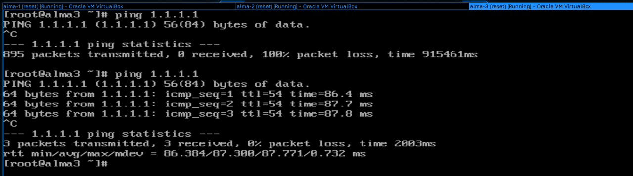
Let’s check ping:
ping 1.1.1.1
Pings are coming.
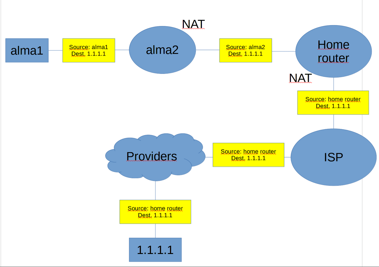
The result is the following scheme. When alma1 tries to contact server 1.1.1.1, it first sends a packet to alma2, which intercepts the packet and sends it to my home router. Next, my home router will click the packet and send it to the provider. If my router has the internal address of the provider, that is. gray IP, then the provider in turn is pressed, but if the provider gives me a public address – then it simply redirects the packet to the next provider, say, a state one. And further along the chain from one provider to another, the packet is forwarded until it reaches server 1.1.1.1. And then the server will be able to answer, because it knows where.
In fact, I could have avoided double NAT if I had routed to my GNS’s internal network via alma2 on my home router. And then my computer would be able to see all the virtual machines because it would send all the packets to my home router, which would forward them to alma2, which in turn would forward to alma1 and 3.
But I want our grid in GNS to remain isolated and the only way to get to it would be a single external alma2 address.
Summing up everything we went through today:
Rename alma1 to user1 and leave only vlan1 with the address 1.101 on it.
Rename alma2 to router1 and change the IP addresses of all 3 vlans to 1. Usually, in organizations, gateways are given either the first or the last subnet address.
Rename alma3 to server1 and leave only 2 and 3 vlans on it. Change the addresses to 2.101 and 3.101, respectively.
And of course, make sure everything is working – that everyone is pinging each other on different networks, and that all hosts are pinging 1.1.1.1.
Let’s summarize. Today we explained what a subnet is, what a subnet mask is, why routing is needed, why a gateway is needed and what is the meaning of NAT. These are, of course, the basics of routing, but for a system administrator, this is enough for most tasks.