Flipper Zero is not just a hacker gadget, but a full-fledged hardware platform with an extended GPIO interface. In this article, you will learn what the GPIO in Flipper Zero is, how to use it to connect external modules, how power on pin 1 and pin 9 works, what DFU mode is and how to avoid mistakes when installing the board. The guide covers the full pinout, current limits, UART, SWD, SPI, I2C connections and important safety rules. You will also learn how to use the GPIO menu, enable 5V on pin 1, manually switch pins and control them directly through Flipper. This guide is suitable for both beginners to working with Flipper Zero and experienced embedded developers.
Disclaimer: The information provided in this article is for educational and informational purposes only. The author is not responsible for any misuse or incorrect use of the Flipper Zero device.
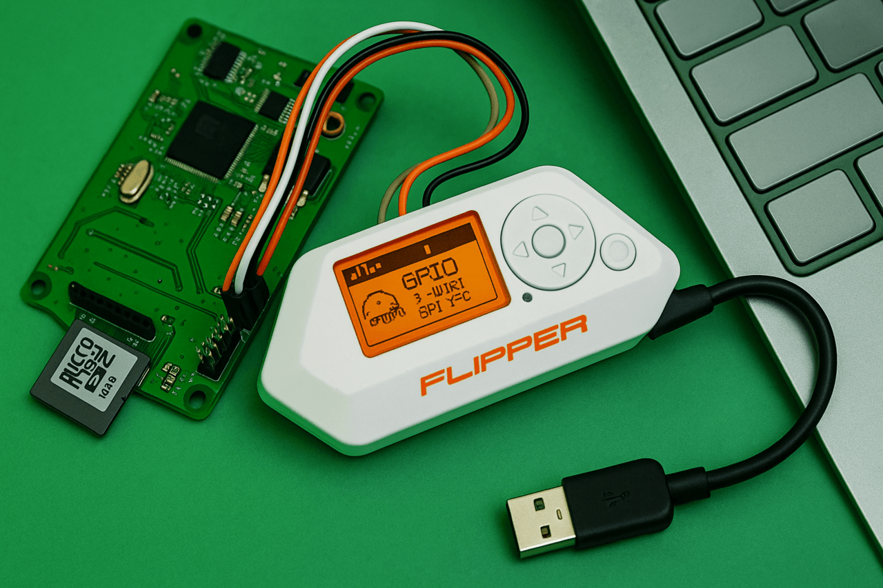
The GPIO (General Purpose Input/Output) interface is a set of pins that allow Flipper Zero to physically interact with other electronic devices. With it, you can not only read or send signals to external components, but also fully control them, flash microcontrollers, send and receive data via UART, run your own code, display messages on the screen and debug devices.
In addition, the GPIO ports open up the possibility of turning Flipper into a USB-UART, USB-SPI or USB-I2C converter. This means that it can work as a bridge between your computer and any external device that supports the corresponding exchange protocol.
However, to fully work with GPIO, you need to have a microSD card inserted, since Flipper stores the necessary databases on it. Without a card, access to the GPIO menu and functions will be partially or completely limited.
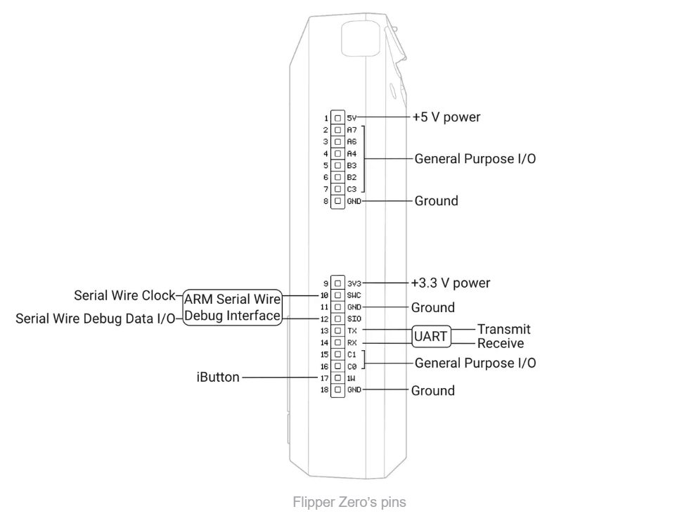
The Flipper Zero has 18 physical pins located on the top of the case. They are clearly divided into three main categories: power, ground (GND), and functional signal lines – i.e. GPIO inputs/outputs.
The first pin (Pin 1) is responsible for supplying 5 V power, but it is disabled by default – it must be enabled manually via the Flipper menu. The ninth pin (Pin 9) is 3.3 V, and it is always enabled if the Flipper is not updating the firmware or mounting a memory card.
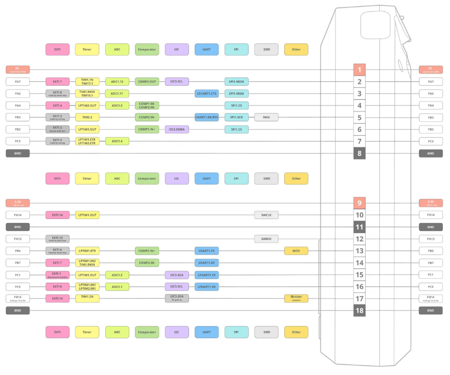
The GPIO pins (e.g. PA7, PA6, PB3, PC3) are connected to the STM32WB55 microcontroller through 51 Ohm resistors and have built-in protection against static discharge (ESD), which prevents damage from accidental contact or incorrect connection.
Separately, there are UART transmission (Pin 13, TX) and reception (Pin 14, RX) pins, as well as special debug pins: SWDIO and SWCLK (pins 10 and 11, respectively) – they are needed for software debugging via ARM interfaces.
Detailed information about the location of the thermostats and the functionality of the contacts can be found in the image below.
DFU (Device Firmware Update) is a special mode of operation of the microcontroller, in which it can receive firmware directly via USB or UART. In this state, all GPIO pins (except Pin 17, which is used for iButton) are automatically switched to input mode.
This means that any active load or attempt to apply a signal to a pin that was an output can lead to unpredictable results. This nuance should be taken into account when connecting logic circuits or adapters. If DFU is activated while the module is connected, it is best to disable it or make sure that the logic of the operation will not be broken.
Pin 9 is a stabilized 3.3V power supply. It is used not only to power external devices, but also for the microSD card itself inside the Flipper. Its maximum is 1.2A, which allows you to connect most sensors, displays, communication modules and microcontrollers. But you need to remember: when updating or rebooting the microSD card, the power from pin 9 disappears for a moment. If the connected module consumes a lot of power, this can cause crashes or even damage the card’s file system.
Pin 1 outputs 5V, but is disabled by default. To activate it, you need to manually enter the menu: Main Menu → GPIO → “5V on GPIO” → ON. This pin can be used if the module requires a higher voltage than 3.3V. The source is either USB or the device’s battery. The current is no more than 1.2A, otherwise the Flipper goes into protection mode.
Flipper Zero is built on the STM32WB55, which means that the GPIO pins operate in the 3.3 Volt range. They are partially tolerant to 5 V, but only in input mode. If you configure a pin as an output, it can no longer withstand 5 V – and this can damage it.
The total power consumption of all pins should not exceed 5 W. Each pin has a maximum of 20 mA. If these limits are exceeded, the Flipper’s built-in battery may go into emergency protection mode and the device will turn off.
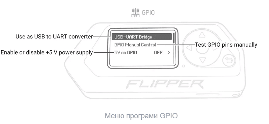
Flipper has a separate menu for working with GPIO:
activate USB–UART Bridge mode (works as a USB converter);
test pins manually, individually or all together (via OK);
enable or disable 5V on pin 1.
The list of pins that can be configured: PA7 (pin 2), PA6 (pin 3), PA4 (pin 4), PB3 (pin 5), PB2 (pin 6), PC3 (pin 7), PC1 (pin 15), PC0 (pin 16), or all at once – ALL.
The menu interface is clear and adapted for quick checking or switching of pin logic.
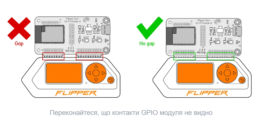
It is important to insert the external module correctly into the GPIO holes of your Flipper Zero. If your Flipper Zero is not in a silicone case, insert the module all the way in so that there is no gap between the Flipper Zero and the module. You may need to use more force to fully insert it.
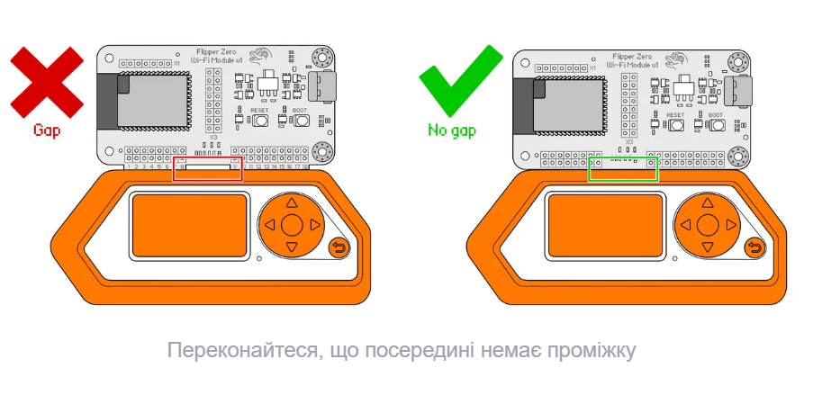
If your Flipper Zero is in a silicone case, insert the module all the way in so that there is no gap in the middle between the silicone case and the module.
Correct installation of the external module is critical for reliable GPIO operation.
If the Flipper is without a silicone case, the module must be inserted completely – without a gap between the case and the board.
If the Flipper is in a case, make sure that the case does not interfere with a tight fit. Any gap between the case and the board leads to an unstable connection.
Visual inspection: the pins should not be visible. If visible, the module is installed incorrectly or not deep enough.
In conclusion, the Flipper Zero GPIO interface is a powerful tool for interacting with the external hardware environment and opens up wide possibilities for engineers, hackers and microelectronics enthusiasts. Its flexibility in connecting modules, the ability to work as a USB converter, as well as support for manual pin control make it a universal solution for tasks of varying complexity.
However, to use these capabilities effectively and safely, it is important to understand the pinout logic, comply with power requirements and carefully monitor the pin states – especially in critical modes, such as DFU. It is the correct configuration and attention to detail that allows you to unlock the full potential of Flipper Zero as a truly multifunctional hardware core.