In this part of our guide, you will learn how to create your own spaceship interface using Arduino. We will take you step by step through how to connect LEDs, buttons, and program them to work like in a real 70s science fiction movie. Arduino is a versatile tool for creating electronic projects that allows you to control various components, including LEDs, with simple code.

Now that you’ve got the basics of electricity under control, it’s time to move onto controlling things with your Arduino. In this project, you’ll be building something that could have been a spaceship interface in a 1970s science fiction movie. You’ll make a cool control panel with a switch and lights that turn on when you press the switch. You can decide whether the lights mean “Engage Hyperdrive” or “Fire the lasers!”. A green LED will be on, until you press a button. When the Arduino gets a signal from the button, the green light will turn off and 2 other lights will start blinking.
The Arduino’s digital pins can read only two states: when there is voltage on an input pin, and when there’s not. This kind of input is normally called digital (or sometimes binary, for two-states). These states are commonly referred to as HIGH and LOW. HIGH is the same as saying “there’s voltage here!” and LOW means “there’s no voltage on this pin!”. When you turn an OUTPUT pin HIGH using a command called digitalWrite(), you’re turning it on. Measure the voltage between the pin and ground, you’ll get 5 volts. When you turn an OUTPUT pin LOW, you’re turning it off.
The Arduino’s digital pins can act as both inputs and outputs. In your code, you’ll configure them depending on what you want their function to be. When the pins are outputs, you can turn on components like LEDs. If you configure the pins as inputs, you can check if a switch is being pressed or not. Since pins 0 and 1 are used for communicating with the computer, it’s best to start with pin 2.
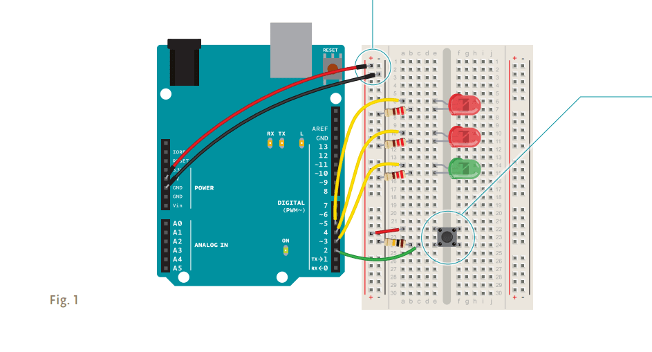
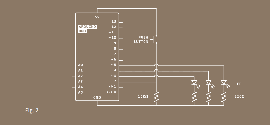
Wire up your breadboard to the Arduino’s 5V and ground connections, just like the previous project. Place the two red LEDs and one green LED on the breadboard. Attach the cathode (short leg) of each LED to ground through a 220-ohm resistor. Connect the anode (long leg) of the green LED to pin 3. Connect the red LEDs’ anodes to pins 4 and 5, respectively.
Place the switch on the breadboard just as you did in the previous project. Attach one side to power, and the other side to digital pin 2 on the Arduino. You’ll also need to add a 10k-ohm resistor from ground to the switch pin that connects to the Arduino. That pull-down resistor connects the pin to ground when the switch is open, so it reads LOW when there is no voltage coming in through the switch.
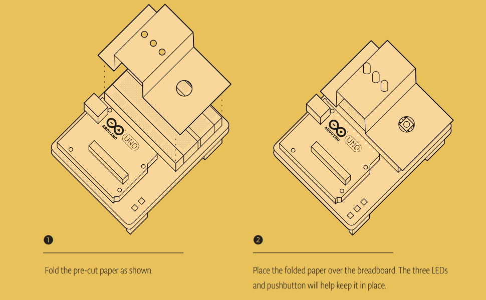
You can cover the breadboard the template provided in the kit. Or you can decorate it to make your own launch system. The lights turning on and off mean nothing by themselves, but when you put them in a control panel and give them labels, they gain meaning. What do you want the green LED to mean? What do the flashing red LEDs mean? You decide!
THE CODE
Some notes before you start
Every Arduino program has two main functions. Functions are parts of a computer program that run specific commands. Functions have unique names, and are “called” when needed. The necessary functions in an Arduino program are called setup() and loop(). These functions need to be declared, which means that you need to tell the Arduino what these functions will do. setup() and loop() are declared as you see on the right.
In this program, you’re going to create a variable before you get into the main part of the program. Variables are names you give to places in the Arduino’s memory so you can keep track of what is happening. These values can change depending on your program’s instructions.
Variable names should be descriptive of whatever value they are storing. For example, a variable named switchState tells you what it stores: the state of a switch. On the other hand, a variable named “x” doesn’t tell you much about what it stores.
Let’s start coding:
To create a variable, you need to declare what type it is. The data type int will hold a whole number (also called an integer); that’s any number without a decimal point. When you declare a variable, you usually give it an initial value as well. The declaration of the variable as every statement must end with a semicolon (;).
Configure pin functionality:
The setup() runs once, when the Arduino is first powered on. This is where you configure the digital pins to be either inputs or outputs using a function named pinMode(). The pins connected to LEDs will be OUTPUTs and the switch pin will be an INPUT.
Create the loop function:
The loop() runs continuously after the setup() has completed. The loop() is where you’ll check for voltage on the inputs, and turn outputs on and off. To check the voltage level on a digital input, you use the function digitalRead() that checks the chosen pin for voltage. To know what pin to check, digitalRead() expects an argument. Arguments are information that you pass to functions, telling them how they should do their job. For example, digitalRead() needs one argument: what pin to check. In your program, digitalRead() is going to check the state of:
void setup(){
}
void loop(){
}
{ Curly brackets } Any code you write inside the curly brackets will be executed when the function is called.
int switchState = 0
void setup(){
 pinMode(3,OUTPUT);
 pinMode(4,OUTPUT);
 pinMode(5,OUTPUT);
 pinMode(2,INPUT);
}
Case sensitivity. Pay attention to the case sensitivity in your code. For example, pinMode is the name of a command, but pinmode will produce an error.
void loop(){
 switchState = digitalRead(2);
 // this is a comment
Comments. If you ever want to include natural language in your program, you can leave a comment. Comments are notes you leave for yourself that the computer ignores. To write a comment, add two slashes // The computer will ignore anything on the line after those slashes.
pin 2 and store the value in the switchState variable. If there’s voltage on the pin when digitalRead() is called, the switchState variable will get the value HIGH (or 1). If there is no voltage on the pin, switchState will get the value LOW (or 0).
Above, you used the word if to check the state of something (namely, the switch position). An if() statement in programming compares two things, and determines whether the comparison is true or false. Then it performs actions you tell it to do. When comparing two things in programming, you use two equal signs ==. If you use only one sign, you will be setting a value instead of comparing it.
digitalWrite() is the command that allows you to send 5V or 0V to an output pin. digitalWrite() takes two arguments: what pin to control, and what value to set that pin, HIGH or LOW. If you want to turn the red LEDs on and the green LED off inside your if() statement, your code would look like this .
If you run your program now, the lights will change when you press the switch. That’s pretty neat, but you can add a little more complexity to the program for a more interesting output.
You’ve told the Arduino what to do when the switch is open. Now define what happens when the switch is closed. The if() statement has an optional else component that allows for something to happen if the original condition is not met. In this case, since you checked to see if the switch was LOW, write code for the HIGH condition after the else statement.
To get the red LEDs to blink when the button is pressed, you’ll need to turn the lights off and on in the else statement you just wrote. To do this, change the code to look like this.
Now your program will flash the red LEDs when the switch button is pressed.
After setting the LEDs to a certain state, you’ll want the Arduino to pause for a moment before changing them back. If you don’t wait, the lights will go back and forth so fast that it will appear as if they are just a little dim, not on and off. This is because the Arduino goes through its loop() thousands of times each second, and the LED will be turned on and off quicker than we can perceive.
The delay() function lets you stop the Arduino from executing anything for a period of time. delay() takes an argument that determines the number of milliseconds before it executes the next set of code. There are 1000 milliseconds in one second. delay(250) will pause for a quarter second.
if (switchState == LOW) {
 // the button is not pressed
 digitalWrite(3, HIGH); // green LED
 digitalWrite(4, LOW); // red LED
 digitalWrite(5, LOW); // red LED
 }
 else { // the button is pressed
 digitalWrite(3, LOW);
 digitalWrite(4, LOW);
 digitalWrite(5, HIGH);
 delay(250); // wait for a quarter second
 // toggle the LEDs
 digitalWrite(4, HIGH);
 digitalWrite(5, LOW);
 delay(250); // wait for a quarter second
 }
} // go back to the beginning of the loop
It can be helpful to write out the flow of your program in pseudocode: a way of describing what you want the program to do in plain language, but structured in a way that makes it easy to write a real program from it. In this case you’re going to determine if switchState is HIGH (meaning the button is pressed) or not.
If the switch is pressed, you’ll turn the green LED off and the red ones on. In pseudocode, the statement could look like this: if the switchState is LOW: turn the green LED on turn the red LEDs off
if the switchState is HIGH: turn the green LED off turn the red LEDs on
Once your Arduino is programmed, you should see the green light turn on. When you press the switch, the red lights will start flashing, and the green light will turn off. Try changing the time of the two delay() functions; notice what happens to the lights and how the response of the system changes depending on the speed of the flashing. When you call a delay() in your program, it stops all other functionality.
No sensor readings will happen until that time period has passed. While delays are often useful, when designing your own projects make sure they are not unnecessarily interfering with your interface.
How would you get the red LEDs to be blinking when your program starts? How could you make a larger, or more complex interface for your interstellar adventures with LEDs and switches?
When you start creating an interface for your project, think about what people’s expectations are while using it. When they press a button, will they want immediate feedback? Should there be a delay between their action and what the Arduino does? Try and place yourself in the shoes of a different user while you design, and see if your expectations match up to the reality of your project.
In this project, you created your first Arduino program to control the behavior of some LEDs based on a switch. You’ve used variables, an if()…else statement, and functions to read the state of an input and control outputs.
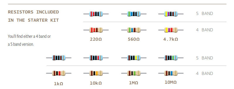
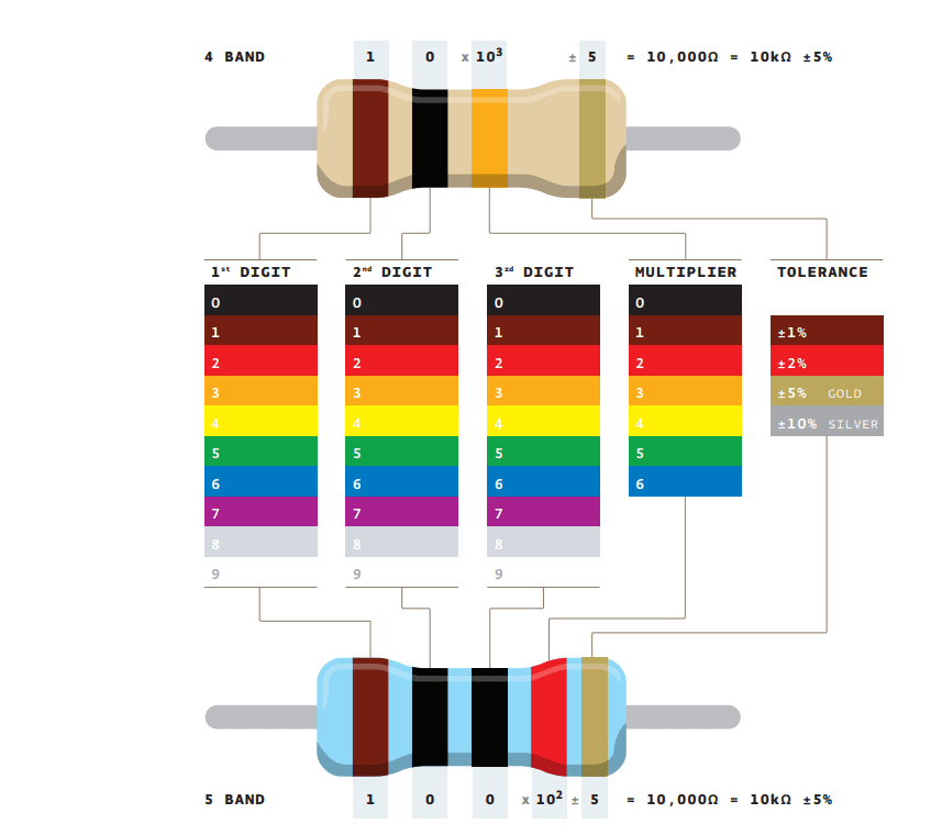
Resistor values are marked using colored bands, according to a code developed in the 1920s, when it was too difficult to write numbers on such tiny objects. Each color corresponds to a number, like you see in the table below. Each resistor has either 4 or 5 bands. In the 4-band type, the first two bands indicate the first two digits of the value while the third one indicates the number of zeroes that follow (technically it reprents the power of ten). The last band specifies the tolerance: in the example below, gold indicates that the resistor value can be 10k ohm plus or minus 5%.
RESISTORS INCLUDED 5 BAND IN THE STARTER KIT