Readers will learn how to create a light theremin on Arduino using a photoresistor and a piezoelectric element. The article explains the principle of operation of a traditional theremin and its Arduino-based analogue, where changing illumination affects the frequency of the sound. The process of calibrating the sensor, using the tone() function to generate sound, and the principle of operation of the semiconductor photoresistor in the circuit are described.

A theremin is an instrument that makes sounds based on the movements of a musician’s hands around the instrument. You’ve probably heard one in scary movies. The theremin detects where a performer’s hands are in relation to two antennas by reading the capacitive change on the antennas.
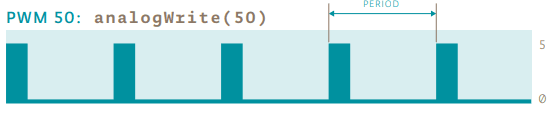
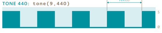
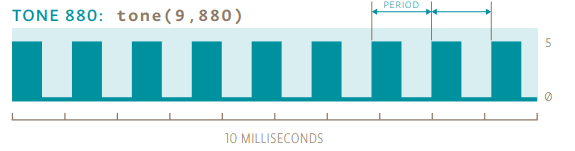
These antennas are connected to analog circuitry that create the sound. One antenna controls the frequency of the sound and the other controls volume. While the Arduino can’t exactly replicate the mysterious sounds from this instrument, it is possible to emulate them using the tone() function. Fig. 1 shows the difference between the pulses emitted by analogWrite() and tone(). This enables a transducer like a speaker or piezo to move back and forth at different speeds.

Instead of sensing capacitance with the Arduino, you’ll be using a photoresistor to detect the amount of light. By moving your hands over the sensor, you’ll change the amount of light that falls on the photoresistor’s face, as you did in Project 4. The change in the voltage on the analog pin will determine what frequency note to play.
You’ll connect the photoresistors to the Arduino using a voltage divider circuit like you did in Project 4. You probably noticed in the earlier project that when you read this circuit using analogRead(), your readings didn’t range all the way from 0 to 1023. The fixed resistor connecting to ground limits the low end of the range, and the brightness of your light limits the high end.
Instead of settling for a limited range, you’ll calibrate the sensor readings getting the high and low values, mapping them to sound frequencies using the map() function to get as much range out of your theremin as possible. This will have the added benefit of adjusting the sensor readings whenever you move your circuit to a new environment, like a room with different light conditions.
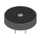
A piezo is a small element that vibrates when it receives electricity. When it moves, it displaces air around it, creating sound waves.

Traditional theremins can control the frequency and the volume of sound. In this example, You’ll be able to control the frequency only. While you can’t control the volume through the Arduino, it is possible to change the voltage level that gets to the speaker manually. What happens if you put a potentiometer in series with pin 8 and the piezo? What about another photoresistor?
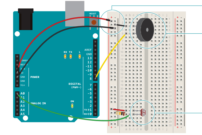
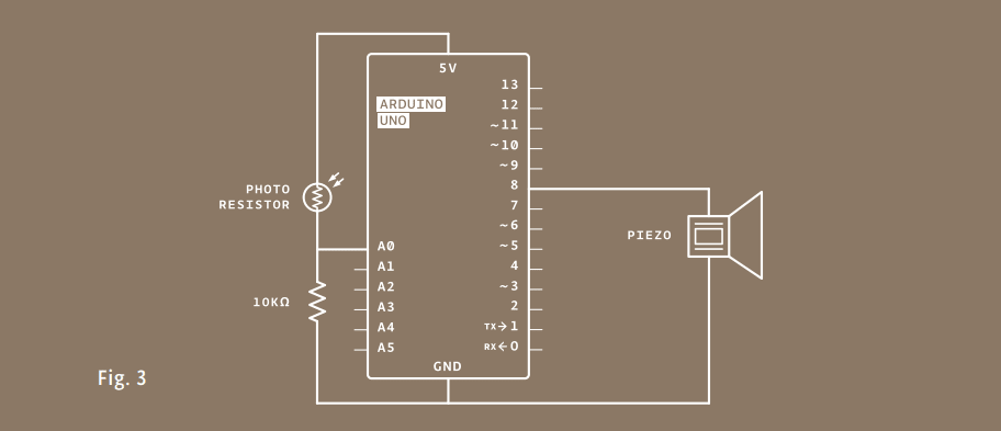
On your breadboard, connect the outer bus lines to power and ground.
Take your piezo, and connect one end to ground, and the other to digital pin 8 on the Arduino.
Place your photoresistor on the breadboard, connecting one end to 5V. Connect the other end to the Arduino’s analogIn pin 0, and to ground through a 10-kilohm resistor. This circuit is the same as the voltage divider circuit in Project 4.
Create variables for calibrating the sensor. Create a variable to hold the analogRead() value from the photoresistor. Next, create variables for the high and low values. You’re going to set the initial value in the sensorLow variable to 1023, and set the value of the sensorHigh variable to 0. When you first run the program, you’ll compare these numbers to the sensor’s readings to find the real maximum and minimum values.
Name a constant for your calibration indicator. Create a constant named ledPin. You’ll use this as an indicator that your sensor has finished calibrating. For this project, use the on-board LED connected to pin 13.
Set digital pin direction and turn it high. In the setup(), change the pinMode() of ledPin to OUTPUT, and turn the light on.
Use a while() loop for calibration. The next steps will calibrate the sensor’s maximum and minimum values. You’ll use a while() statement to run a loop for 5 seconds. while() loops run until a certain condition is met. In this case you’re going to use the millis() function to check the current time. millis() reports how long the Arduino has been running since it was last powered on or reset.
Compare sensor values for calibration. In the loop, you’ll read the value of the sensor; if the value is less than sensorLow (initially 1023), you’ll update that variable. If it is greater than sensorHigh (initially 0), that gets updated.
Indicate calibration has finished. When 5 seconds have passed, the while() loop will end. Turn off the LED attached to pin 13. You’ll use the sensor high and low values just recorded to scale the frequency in the main part of your program.
int sensorValue;
int sensorLow = 1023;
int sensorHigh = 0;
const int ledPin = 13;
void setup() {
 pinMode(ledPin, OUTPUT);
 digitalWrite(ledPin, HIGH);
 while (millis() < 5000) {
 sensorValue = analogRead(A0);
 if (sensorValue > sensorHigh) {
 sensorHigh = sensorValue;
 }
 if (sensorValue < sensorLow) {
 sensorLow = sensorValue;
 }
 }
 digitalWrite(ledPin, LOW);
}
while()<br />arduino.cc/while
Read and store the sensor value. In the loop(), read the value on A0 and store it in sensorValue.
Map the sensor value to a frequency. Create a variable named pitch. The value of pitch is going to be mapped from sensorValue. Use sensorLow and sensorHigh as the bounds for the incoming values. For starting values for output, try 50 to 4000. These numbers set the range of frequencies the Arduino will generate.
Play the frequency. Next, call the tone() function to play a sound. It takes three arguments : what pin to play the sound on (in this case pin 8), what frequency to play (determined by the pitch variable), and how long to play the note (try 20 milliseconds to start). Then, call a delay() for 10 milliseconds to give the sound some time to play.
When you first power the Arduino on, there is a 5 second window for you to calibrate the sensor. To do this, move your hand up and down over the photoresistor, changing the amount of light that reaches it. The closer you replicate the motions you expect to use while playing the instrument, the better the calibration will be.
After 5 seconds, the calibration will be complete, and the LED on the Arduino will turn off. When this happens, you should hear some noise coming from the piezo! As the amount of light that falls on the sensor changes, so should the frequency that the piezo plays.
void loop() {
 sensorValue = analogRead(A0);
 int pitch =
 map(sensorValue,sensorLow,sensorHigh, 50, 4000);
 tone(8,pitch,20);
 delay(10);
}

The range in the map() function that determines the pitch is pretty wide, try changing the frequencies to find ones that are the right fit for your musical style.

The tone() function operates very much like the PWM in analogWrite() but with one significant difference. In analogWrite() the frequency is fixed; you change the ratio of the pulses in that period of time to vary the duty cycle. With tone() you’re still sending pulses, but changing the frequency of them. tone() always pulses at a 50% duty cycle (half the time the pin is high, the other half the time it is low).
The tone() function gives you the ability to generate different frequencies when it pulses a speaker or piezo. When using sensors in a voltage divider circuit, you probably won’t get a full range of values between 0-1023. By calibrating sensors, it’s possible to map your inputs to a useable range.