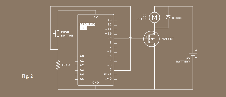
Controlling motors with Arduino opens up new possibilities for creating interactive projects. However, it is more complicated than controlling LEDs, as motors require more current than the microcontroller can provide and can generate reverse voltages that can damage the circuit. This project uses a transistor as a switch to control the motor, as well as a diode to protect against dangerous reverse current. The entire circuit consists of an Arduino, a momentary switch, a 9V motor, a transistor, and a diode.

Make Arduino spin a color wheel using a motor
Controlling motors with an Arduino is more complicated than just controlling LEDs for a couple of reasons. First, motors require more current than the Arduino’s output pins can supply, and second, motors can generate their own current through a process called induction, which can damage your circuit if you don’t plan for it. However, motors make it possible to move physical things, making your projects much more exciting. They’re worth the complications!
Moving things takes a lot of energy. Motors typically require more current than the Arduino can provide. Some motors require a higher voltage as well. To start moving, and when it has a heavy load attached, a motor will draw as much current as it can. The Arduino can only provide 40 milliamps (mA) from its digital pins, much less than what most motors require to work.
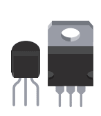
Transistors are components that allow you to control high current and high voltage power sources from the low current output of the Arduino. There are many different kinds, but they work on the same principle. You can think of transistors as digital switches. When you provide voltage to one of the transistor’s pins, called the gate, it closes the circuit between the other two pins, called the source and drain. This way, you can turn a higher current/voltage motor on and off with your Arduino.
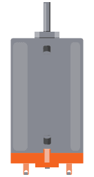
Motors are a type of inductive device. Induction is a process by which a changing electrical current in a wire can generate a changing magnetic field around the wire. When a motor is given electricity, a tightly wound coil inside the housing of copper creates a magnetic field. This field causes the shaft (the part that sticks out of the housing) to spin around.
The reverse is also true: a motor can generate electricity when the shaft is spun around. Try attaching an LED to the two leads of your motor, then spin the shaft with your hand. If nothing happens, spin the shaft the other way. The LED should light up. You’ve just made a tiny generator out of your motor.
When you stop supplying energy to a motor, it will continue to spin, because it has inertia. When it’s spinning, it will generate a voltage in the opposite direction than the current you gave it. You saw this effect when you made your motor light up an LED. This reverse voltage, sometimes called back-voltage, can damage your transistor. For this reason, you should put a diode in parallel with the motor, so that the back voltage passes through the diode. The diode will only allow electricity to flow in one direction, protecting the rest of the circuit.
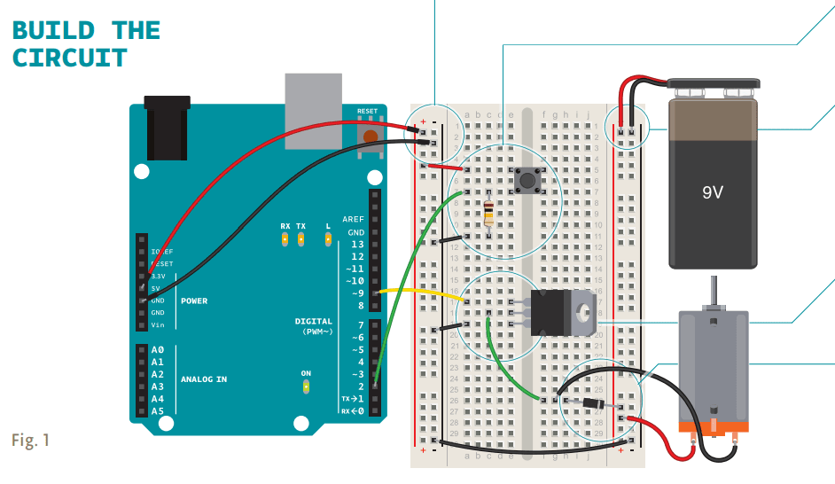
Connect power and ground to your breadboard through the Arduino.
Add a momentary switch to the board, connecting one side to power, and the other side to digital pin 2 on the Arduino. Add a 10-kilohm pull-down resistor to ground on the output pin of the switch.
When using circuits with different voltages, you have to connect their grounds together to provide a common ground. Plug the 9V battery snap into your breadboard. Connect ground from the battery to ground of your Arduino on the breadboard with a jumper, as shown in Fig. 1. Then attach the motor’s free lead to the 9V power.
Place the transistor on the board. Look at the component so that the metal tab is facing away from you. Connect digital pin 9 to the left pin on the transistor. This pin is called the gate. A change in voltage on the gate makes a connection between the other two pins. Connect one end of the motor to the middle pin of the transistor. This pin is called the drain. When the Arduino activates the transistor by supplying voltage to the gate, this pin will be connected to the third pin, called the source. Connect the source to ground.
Next, connect the motor’s voltage supply to the motor and breadboard. The last component to be added is the diode. The diode is a polarized component, it can go only one way in the circuit. Notice that the diode has a stripe on one end. That end is the negative end, or cathode, of the diode. The other end is the positive end, or anode. Connect the anode of the diode to the ground of the motor and the cathode of the diode to the power of the motor. See Fig. 1. This may seem backwards, and in fact, it is. The diode will help prevent any back-voltage generated by the motor from going back into your circuit. Remember, back voltage will flow in the opposite direction of the voltage that you supply.

LEDs are diodes too, in case you were wondering why their leads were also called anodes and cathodes. There are many kinds of diodes, but they all share one trait. They allow current to flow from anode to cathode, but not the reverse.
Name your constants and variables. The code is remarkably similar to the code you first used for turning on an LED. First of all, set up some constants for the switch and motor pins and a variable named switchState to hold the value of the switch.
Declare the pins’ direction. In your setup(), declare the pinMode() of the motor (OUTPUT) and switch (INPUT) pins.
Read the input, pull the output high if pressed. Your loop() is straightforward. Check the state of the switchPin with digitalRead(). If the switch is pressed, turn the motorPin HIGH. If it is not pressed, turn the pin LOW. When HIGH, the transistor will activate, completing the motor circuit. When LOW, the motor will not spin.
Motors have an optimal operating voltage. They will work on as little as 50% of the rated voltage and as much as 50% over that number. If you vary the voltage, you can change the speed at which the motor rotates. Don’t vary it too much, though, or you will burn out your motor.
Motors require special consideration when being controlled by a microcontroller. Typically the microcontroller cannot provide enough current and/or voltage to power a motor. Because of this, you use transistors to interface between the two. It’s also smart to use diodes to prevent damaging your circuit.
const int switchPin = 2;
const int motorPin = 9;
int switchState = 0;
void setup() {
 pinMode(motorPin, OUTPUT);
 pinMode(switchPin, INPUT);
}
void loop(){
 switchState = digitalRead(switchPin);
 if (switchState == HIGH) {
 digitalWrite(motorPin, HIGH);
 }
 else {
 digitalWrite(motorPin, LOW);
 }
}

Transistors are solid state devices, they have no moving parts. Because of this, you can switch them on and off very quickly. Try hooking up a potentiometer to an analog input and use that to PWM the pin that controls the transistor. What do you think will happen to the motor’s speed if you vary the voltage it’s getting? Using your patterns on your spinner, can you get different visual effects?
USE IT
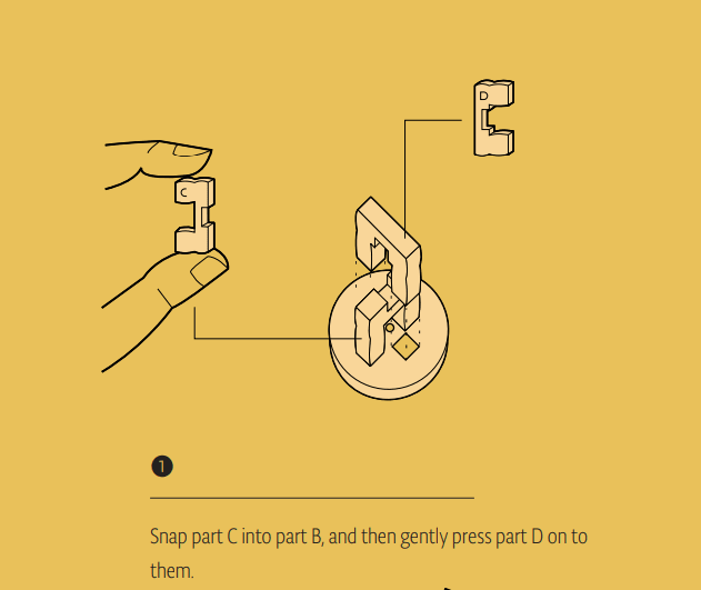
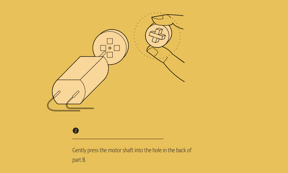
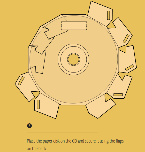
Assemble the CD hub as shown in step 1, and attach it to the motor as shown in step 2. Attach the die-cut paper pattern to a CD as shown in step 3. Snap the CD to the hub and secure with a drop of glue. Allow to try before proceeding. Plug a 9V battery to your battery snap. Power your Arduino over USB. When you press the switch on the breadboard, the motor will spin very rapidly.


With the motor spinning as fast as it does, you can probably make a pretty large spinner. Be careful that it doesn’t fly off and poke someone in the eye. Experiment with different patterns on the outside to create visual effects.