17.02.2025
11 min
1288

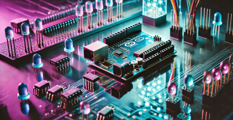
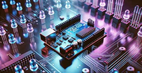
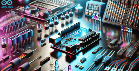
Arduino Uno is a popular board for developing electronic projects based on the ATmega328P microcontroller. It is one of the most common platforms among beginners and experienced developers due to its simplicity, versatility and wide community support.
The board has 14 digital inputs/outputs, of which 6 can operate in PWM mode, as well as 6 analog inputs. It is equipped with a USB connector for connecting to a computer, a power connector and supports the I2C and SPI protocols for interacting with various sensors, displays, motors and other devices.
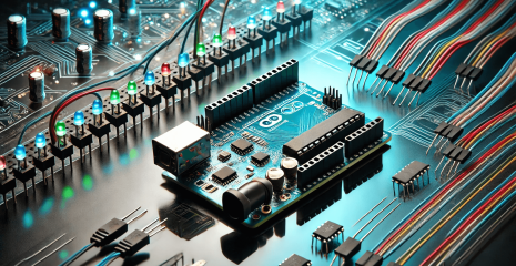
Arduino Uno is often used to create interactive devices, smart control systems, robotics solutions and educational projects. Thanks to its open source code, many libraries and intuitive development environment (Arduino IDE), this board has become a standard in the world of amateur electronics.
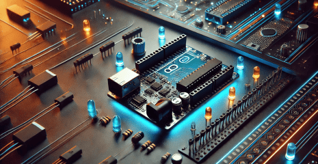
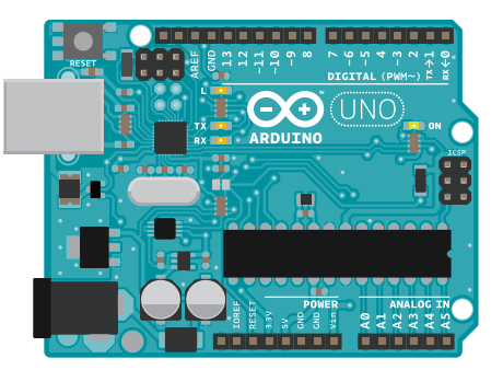
A microcontroller development board that will be the foundation of your projects. It is a simple computer, but there is no way to interact with it yet. You will create circuits and interfaces for interaction and tell the microcontroller how to interact with other components.
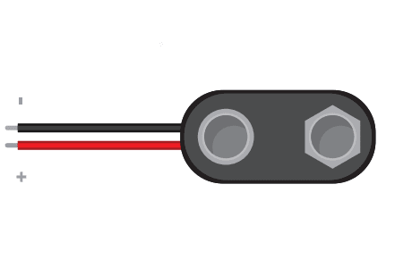
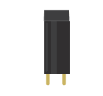
Used to connect a 9V battery to the power wires, which can be easily connected to a breadboard or Arduino. These magnetic fields attract and repel the magnets, causing the shaft to rotate. If the direction of the electricity is reversed, the motor will rotate in the opposite direction.
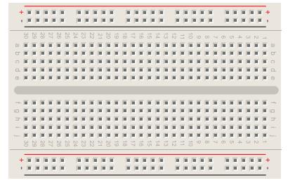
A board on which electronic circuits can be built. It is like a patch panel with rows of holes that allow wires and components to be connected. Versions are available that require soldering, as well as the solderless type used here.
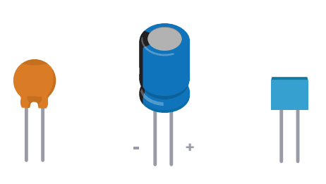
These components store and release electrical energy in a circuit. When the voltage in the circuit is higher than the voltage stored in the capacitor, it passes a current that charges the capacitor. When the voltage in the circuit decreases, the stored charge is released. Often placed between the power supply and ground near a sensor or motor to help smooth out voltage fluctuations.
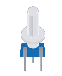
A variable resistor with three pins. Two pins are connected to the ends of a fixed resistor. The middle pin, or wiper, moves across the resistor, dividing it into two halves. When the outsides of the potentiometer are connected to voltage and ground, the middle pin will produce a voltage difference as you turn the knob. Often called a pot.
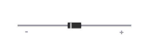
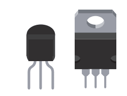
Allows electricity to flow in only one direction. Useful when you have a motor or other high current/voltage load in your circuit. Diodes are polarized, meaning the direction they are placed in the circuit matters. Placed one way, they allow current to pass. Placed the other way, they block it. The anode side is usually connected to the higher energy point in your circuit.
(Red, Green, Blue) – they filter different wavelengths of light. When combined with photoresistors, the sensor only responds to the amount of light of the filtered color.

A circuit that allows you to control the polarity of the voltage applied to a load, usually a motor. The H-bridge in the kit is an integrated circuit, but it can also be built with multiple discrete components.

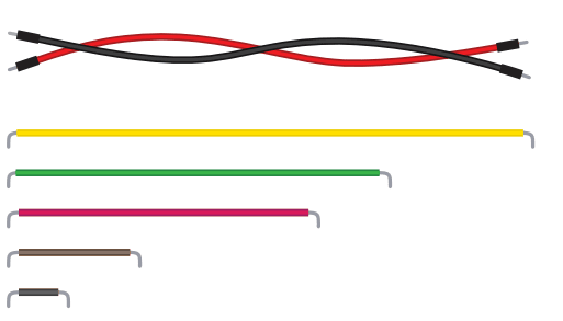
Use them to connect components to each other on the breadboard and to the Arduino.
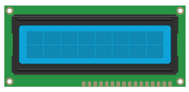
A type of alphanumeric or graphic display based on liquid crystals. LCDs come in many sizes, shapes, and styles. Yours has 2 lines of 16 characters each.
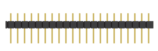
These pins fit into sockets, just like on a breadboard. They make connecting things much easier.
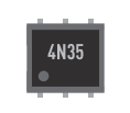
Allows you to connect two circuits that do not have a common power source. Inside there is a small LED that, when lit, causes a photoreceptor inside to close an internal switch. When you apply voltage to the + pin, the LED lights up and the internal switch closes. The two outputs replace the switch in the second circuit.
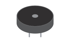
An electrical component that can be used to detect vibration and create noise.
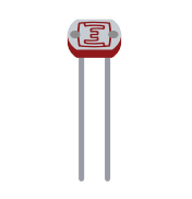
(Also called a photocell or light-dependent resistor.) A variable resistor that changes its resistance depending on the amount of light falling on its surface.
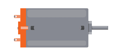
Converts electrical energy into mechanical energy when electricity is applied to its wires. Coils of wire inside the motor become magnetized when current flows through them.
Works like an electronic switch. Useful for controlling high current/high voltage components such as motors. One pin connects to ground, another to the component being controlled, and the third connects to the Arduino. When the component receives voltage on the pin connected to the Arduino, it completes the circuit between ground and the other component.
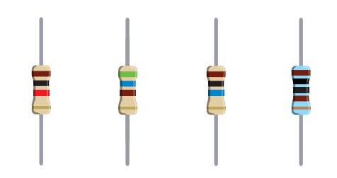
Resistors oppose the flow of electrical energy in a circuit, thereby changing the voltage and current. Resistor values are measured in Ohms (denoted by the Greek symbol omega: Ω). The colored stripes on the sides of the resistors indicate their value (see the resistor color coding table).
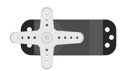
A type of geared motor that can only rotate 180 degrees. It is controlled by sending electrical pulses from your Arduino. These pulses tell the motor which position it should move to.
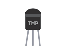
Changes the output voltage depending on the temperature of the component. The outer pins are connected to power and ground. The voltage on the center pin changes as it gets warmer or colder.
A type of switch that opens or closes depending on its orientation. They are usually hollow cylinders with a metal ball inside that connects two wires when tilted in the right direction.
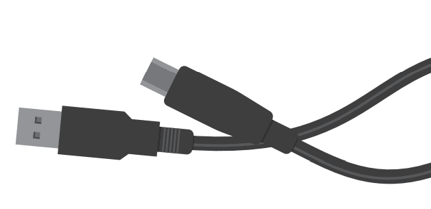
Allows you to connect the Arduino Uno to a personal computer for programming. It also provides power to the Arduino for most of the projects in the kit.
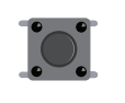
Momentary switches that close a circuit when pressed. They are easy to insert into breadboards. They are suitable for detecting on/off signals.
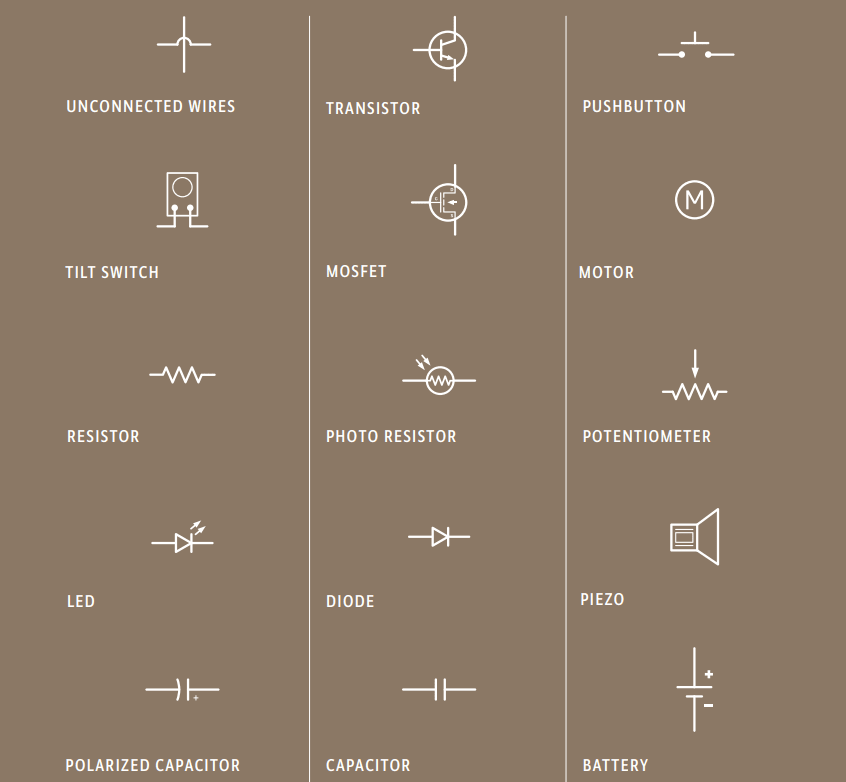
We’ll show you schematics with both realistic illustrations and schematic diagrams. The illustrations will give you an idea of what the layout might look like in one possible implementation of the project.
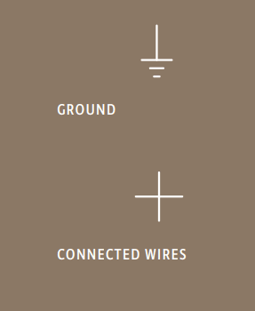
Instead, schematics use symbols to represent the essence of the schematics: they present the components and how they are connected in a clear, concise, and unambiguous way, but not their physical organization. Schematics and schematic symbols are how we communicate about circuits. As you explore the world of electronics, you’ll find that some books and websites only provide schematic diagrams, so learning to read schematics this way is a valuable skill. Here are the symbols we’ll use throughout the book.
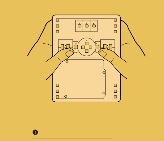
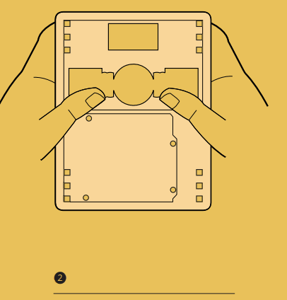
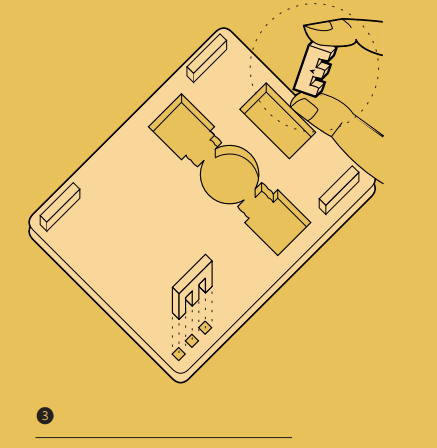
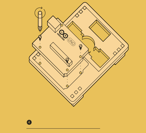
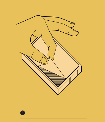
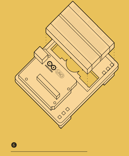
Your starter kit includes a pre-cut wooden base that’s easy to assemble, making all of your projects—whether they’re from this book or not—even easier to work on.
To build it, take the wooden sheet out of the box and follow the instructions on the right. Be careful to only use the parts shown, but don’t lose the other parts: you’ll need them for some projects later. Let’s get started!
The Arduino Uno Starter Kit is a great way to get started in electronics and programming, regardless of your level of experience. Having familiarized yourself with the basic components, you have gained an idea of their role in creating interactive projects.
The most interesting part is ahead! In the following parts, we will look at how to properly connect these components, program the board, and create your own devices.