Arduino opens up endless possibilities for creativity, and in this fourth part of our guide, we’ll learn how to create a colored lamp that responds to changes in lighting. Using an RGB LED, photoresistors, and pulse-width modulation (PWM), you can mix the colors of the light and watch it change smoothly depending on the ambient conditions.

Using a tri-color LED and three photoresistors, you will create a lamp that smoothly changes colors depending on the ambient lighting conditions.
Blinking LEDs can be fun, but what about fading them, or mixing colors? You might expect that it’s just a matter of providing less voltage to an LED to get it to fade.
The Arduino can’t vary the output voltage on its pins, it can only output 5V. Hence you’ll need to use a technique called Pulse Width Modulation (PWM) to fade LEDs. PWM rapidly turns the output pin high and low over a fixed period of time. The change happens faster than the human eye can see. It’s similar to the way movies work, quickly flashing a number of still images to create the illusion of motion.
When you’re rapidly turning the pin HIGH and LOW, it’s as if you were changing the voltage. The percentage of time a pin is HIGH in a period is called duty cycle. When the pin is HIGH for half of the period and LOW for the other half, the duty cycle is 50%. A lower duty cycle gives you a dimmer LED than a higher duty cycle.
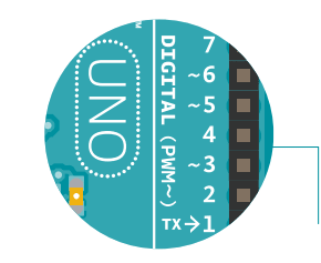
The Arduino Uno has six pins set aside for PWM (digital pins 3, 5, 6, 9, 10, and 11), they can be identified by the ~ next to their number on the board.
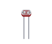
For inputs in this project, you’ll be using photoresistors (sensors that change their resistance depending on the amount of light that hits them, also known as photocells or light-dependent resistors). If you connect one end of the resistor to your Arduino, you can measure the change in resistance by checking the voltage on the pin.
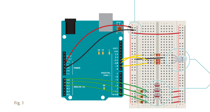
Wire up your breadboard so you have power and ground on both sides, just like the earlier projects.
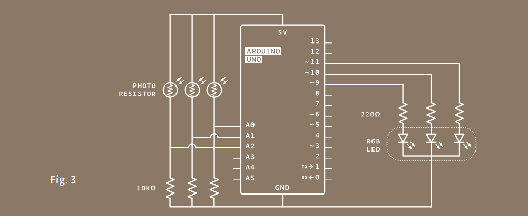
Place the three photoresistors on the breadboard so they cross the center divide from one side to the other, as shown in Fig. 1. Attach one end of each photoresistor to power. On the other side, attach a 10-kilohm resistor to ground. This resistor is in series with the photoresistor, and together they form a voltage divider. The voltage at the point where they meet is proportional to the ratio of their resistances, according to Ohm’s Law (see Project 1 for more on Ohm’s Law). As the resistance of the photoresistor changes when light hits it, the voltage at this junction changes as well. On the same side as the resistor, connect the photoresistors to Analog In pins 0, 1, and 2 with hookup wire.
Take the three colored gels and place one over each of the photoresistors. Place the red gel over the photoresistor connected to A0, the green over the one connected to A1, and the blue over the one connected to A2. Each of these filters lets only light of a specific wavelength through to the sensor it’s covering. The red filter passes only red light, the green filter passes only green light, and the blue filter passes only blue light. This allows you to detect the relative color levels in the light that hits your sensors.
The LED with 4 legs is a common cathode RGB LED. The LED has separate red, green, and blue elements inside, and one common ground (the cathode). By creating a voltage difference between the cathode and the voltage coming out of the Arduino’s PWM pins (which are connected to the anodes through 220-ohm resistors), you’ll cause the LED to fade between its three colors. Make note of what the longest pin is on the LED, place it in your breadboard, and connect that pin to ground. Connect the other three pins to digital pins 9, 10 and 11 in series with 220-ohm resistors. Be sure to connect each LED lead to the correct PWM pin, according to the figure on the left.
Useful constants. Set up constants for the pins you’re using for input and output, so you can keep track of which sensor pairs with which color on the LED. Use const int for the datatype.
Variables to store the sensor readings as well as the light level of each LED. Add variables for the incoming sensor values and for the output values you’ll be using to fade the LED. You can use the int datatype for all the variables.
Setting the direction of the digital pins and setting up the serial port. In the setup(), begin serial communication at 9600 bps. Just like in the previous example, you will use this to see the values of the sensors in the serial monitor. Additionally, you will be able to see the mapped values you’ll use to fade the LED. Also, define the LED pins as outputs with pinMode().
Reading the value of each light sensor. In the loop() read the sensor values on A0, A1, and A2 with analogRead() and store the value in the appropriate variables. Put a small delay() between each analogRead() as the ADC takes a millisecond to do its work.
Report the sensor readings to the computer
Print out the sensor values on one line. The “\t” is the equivalent of pressing the “tab” key on the keyboard.
const int greenLEDPin = 9;
const int redLEDPin = 11;
const int blueLEDPin = 10;
const int redSensorPin = A0;
const int greenSensorPin = A1;
const int blueSensorPin = A2;
int redValue = 0;
int greenValue = 0;
int blueValue = 0;
int redSensorValue = 0;
int greenSensorValue = 0;
int blueSensorValue = 0;
void setup() {
 Serial.begin(9600);
 pinMode(greenLEDPin,OUTPUT);
 pinMode(redLEDPin,OUTPUT);
 pinMode(blueLEDPin,OUTPUT);
}
void loop() {
 redSensorValue = analogRead(redSensorPin);
 delay(5);
 greenSensorValue = analogRead(greenSensorPin);
 delay(5);
 blueSensorValue = analogRead(blueSensorPin);
 Serial.print(“Raw Sensor Values \t Red: “);
 Serial.print(redSensorValue);
 Serial.print(“\t Green: “);
 Serial.print(greenSensorValue);
 Serial.print(“\t Blue: “);
 Serial.println(blueSensorValue);
Converting the sensor readings
The function to change the LED’s brightness via PWM is called analogWrite(). It needs two arguments: the pin to write to, and a value between 0-255. This second number represents the duty cycle the Arduino will output on the specified pin. A value of 255 will set the pin HIGH all the time, making the attached LED as bright as it can be. A value of 127 will set the pin HIGH half the time of the period, making the LED dimmer. 0 would set the pin LOW all the time, turning the LED off. To convert the sensor reading from a value between 0-1023 to a value between 0-255 for analogWrite(), divide the sensor reading by 4.
Print out the new mapped values on their own line.
Once you have your Arduino programmed and wired up, open the serial monitor. The LED will probably be an off-white color, depending on the predominant color of the light in your room. Look at the values coming from the sensors in the serial monitor, if you’re in an environment with stable lighting, the number should probably be fairly consistent.
Turn off the light in the room you’re in and see what happens to the values of the sensors. With a flashlight, illuminate each of the sensors individually and notice how the values change in the serial monitor, and notice how the LED’s color changes. When the photoresistors are covered with a gel, they only react to light of a certain wavelength. This will give you the opportunity to change each of the colors independently.
redValue = redSensorValue/4;
 greenValue = greenSensorValue/4;
 blueValue = blueSensorValue/4;
 Serial.print(“Mapped Sensor Values \t Red: “);
 Serial.print(redValue);
 Serial.print(“\t Green: “);
 Serial.print(greenValue);
 Serial.print(“\t Blue: “);
 Serial.println(blueValue);
 analogWrite(redLEDPin, redValue);
 analogWrite(greenLEDPin, greenValue);
 analogWrite(blueLEDPin, blueValue);
}
You may notice that the photoresistor’s output doesn’t range all the way from 0 to 1023. That’s okay for this project, but for a more detailed explanation of how to calibrate for the range you’re reading, see Project 6.

You’ll probably notice that the LED’s fading is not linear. When the LED is about at half brightness, it appears to stop getting much brighter. This is because our eyes don’t perceive brightness linearly. The brightness of the light depends not only on the level that you analogWrite() but also on the distance of the light from the diffuser, the distance of your eye from the light, and the brightness of the light relative to other light in the room.

How could you use this to let you know if it’s a nice day outside while you’re working inside? What other sorts of sensors can you use to control the LED’s color?

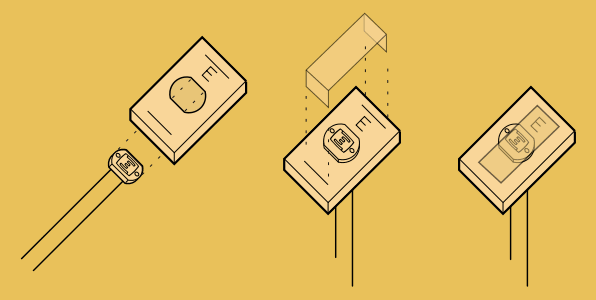
The LED on its own is pretty neat, but it’s not much of a lamp. However, there are a number of different ways you can diffuse the light to make it resemble something like a traditional incandescent. A ping pong ball with a hole cut out for the LED to slide into makes for a nice diffuser. Other ways include covering the light in translucent glue, or sanding the surface of the light. No matter what route you take, you’re going to lose at least a little brightness when it’s diffused, but it will probably look a lot nicer.
No longer limited to just turning lights on and off, you now have control over how bright or dim something will be. analogWrite() is the function that allows you to PWM components attached to pins 3, 5, 6, 9, 10, or 11, varying the duty cycle.