In this article, we’ll take a detailed look at how to build a simple circuit using an LED, buttons, a resistor, and a breadboard. You’ll learn about current, voltage, and resistance, and you’ll also learn the basics of parallel and series connections. We’ll look at how to use an Arduino as a power source, how Ohm’s law works, and why your LEDs will quickly fail without resistors. Step-by-step instructions and clear diagrams will help even beginners learn the basics of electronics and create their first interactive devices.
Let’s make a simple circuit with some switches, an LED, and a resistor.
Electricity is a type of energy, much like heat, gravity, or light. Electrical energy flows through conductors, like wire. You can convert electrical energy into other forms of energy to do something interesting, like turn on a light or make some noise out of a speaker.
The components you might use to do this, like speakers or light bulbs, are electrical transducers. Transducers change other types of energy into electrical energy and vice versa. Things that convert other forms of energy into electrical energy are often called sensors, and things that convert electrical energy into other forms of energy are sometimes called actuators. You will be building circuits to move electricity through different components. Circuits are closed loops of wire with a power source (like a battery) and something to do something useful with the energy, called a load.
In a circuit, electricity flows from a point of higher potential energy (usually referred to as power or +) to a point of lower potential energy. Ground (often represented with a – or GND) is generally the point of least potential energy in a circuit. In the circuits you are building, electricity only flows in one direction. This type of circuit is called direct current, or DC. In alternating current (AC) circuits electricity changes its direction 50 or 60 times a second (depending on where you live). This is the type of electricity that comes from a wall socket.
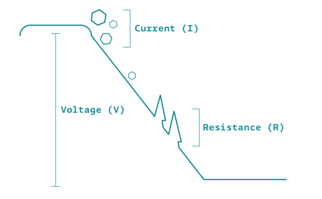
There are a few terms you should be familiar with when working with electrical circuits. Current (measured in amperes, or amps; with the A symbol) is the amount of electrical charge flowing past a specific point in your circuit. Voltage (measured in volts; with the V symbol) is the difference in energy between one point in a circuit and another. And finally, resistance (measured in ohms; with the Ω symbol) is how much a component resists the flow of electrical energy.
One way to imagine this is to think about a rockslide going down a cliff, as shown in Fig. 1. The higher the cliff, the more energy the rocks will have when they hit the bottom. The height of the cliff is like the voltage in a circuit: the higher the voltage at the energy source, the more energy you have to use.
The more rocks you have, the more energy is being carried down the cliff. The number of rocks is like the current in an electrical circuit. The rocks go through bushes on the side of the cliff, losing some energy in the process; the energy is used up to crush the bushes. The bushes are like resistors in a circuit, offering resistance to the electrical flow and converting it into other forms of energy.
There needs to be a complete path from the energy source (power) to the point of least energy (ground) to make a circuit. If there’s no path for the energy to travel, the circuit won’t work.
All the electrical energy gets used up in a circuit by the components in it. Each component converts some of the energy into another form of energy. In any circuit, all of the voltage is converted to another form of energy (light, heat, sound, etc.).
The flow of current at a specific point in a circuit will always be the same coming in and going out.
Electrical current will seek the path of least resistance to ground. Given two possible paths, more of the electrical current will go down the path with less resistance. If you have a connection that connects power and ground together with no resistance, you will cause a short circuit, and the current will try to follow that path. In a short circuit, the power source and wires convert the electrical energy into light and heat, usually as sparks or an explosion. If you’ve ever shorted a battery and seen sparks, you know how dangerous a short circuit can be.
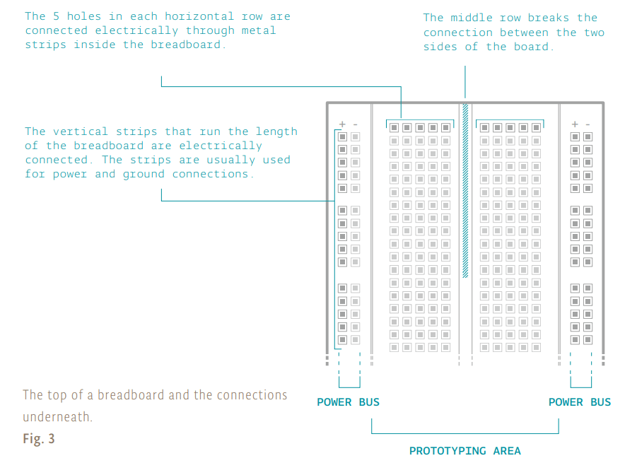
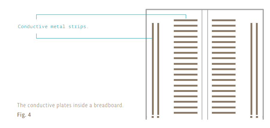
The breadboard is the primary place you will be building circuits. The one that comes in your kit is solderless, so named because you don’t have to solder anything together, sort of like LEGO in electronic form. The horizontal and vertical rows of the breadboard, as shown in Fig. 3, carry electrictricity through thin metal connectors under the plastic with holes.
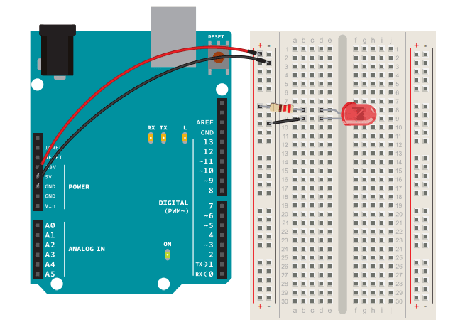
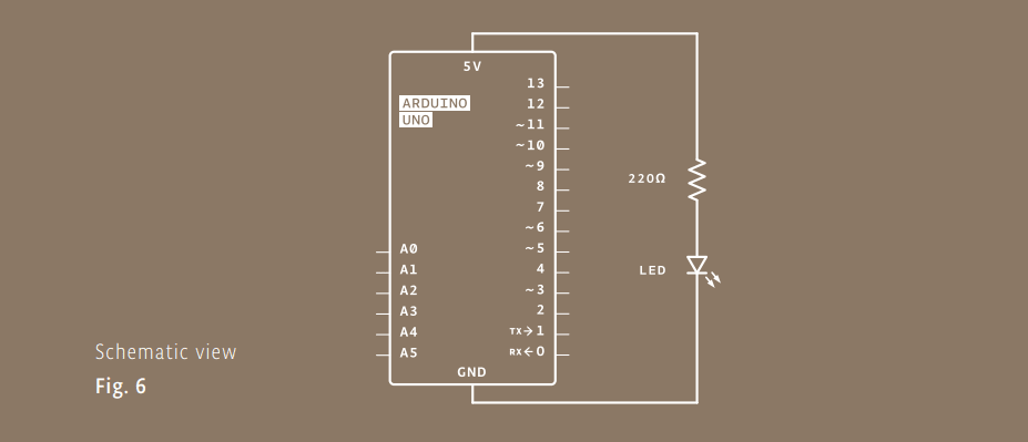
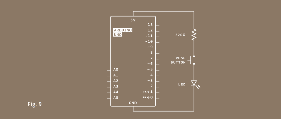
Throughout these projects, you’ll see two views of circuits: one in breadboard view (like in Fig. 5), that looks like the stuff in your kit. The other is a schematic view (like in Fig. 6), which is a more abstract way of showing the relationships between components in a circuit. Schematics don’t always show where components are placed relative to each other, but they show how they are connected.
An LED, or light-emitting diode, is a component that converts electrical energy into light energy. LEDs are polarized components, which means they only allow electricity to flow through them in one direction. The longer leg on the LED is called an anode, it will connect to power. The shorter leg is a cathode and will connect to ground. When voltage is applied to the anode of the LED, and the cathode is connected to ground, the LED emits light.
A resistor is a component that resists the flow of electrical energy (see the components list for an explanation on the colored stripes on the side). It converts some of the electrical energy into heat. If you put a resistor in series with a component like an LED, the resistor will use up some of the electrical energy and the LED will receive less energy as a result. This allows you to supply components with the amount of energy they need. You use a resistor in series with the LED to keep it from receiving too much voltage. Without the resistor, the LED would be brighter for a few moments, but quickly burn out.
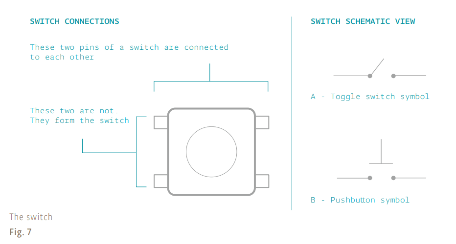
A switch interrupts the flow of electricity, breaking the circuit when open. When a switch is closed, it will complete a circuit. There are many types of switches. The ones in your kit are called momentary switches, or pushbuttons, because they are only closed when pressure is applied.
Your first interactive circuit, using a switch, a resistor and an LED. Arduino is just the power source for this circuit; in later projects, you’ll connect its input and output pins to control more complex circuits.
You’re going to use the Arduino in this project, but only as a source of power. When plugged into a USB port or a 9-volt battery, the Arduino will provide 5 volts between its 5V pin and its ground pin that you can use. 5V = 5 volts, you’ll see it written this way a lot.
If your Arduino is connected to a battery or computer via USB, unplug it before building the circuit!
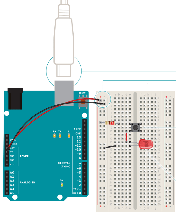
Connect a red wire to the 5V pin on the Arduino, and put the other end in one of the long bus lines in your breadboard. Connect ground on the Arduino to the adjacent bus line with a black wire. It’s helpful to keep your wire color consistent (red for power, black for ground) throughout your circuit.
Now that you have power on your board, place your switch across the center of the board. The switch will sit across the center in one direction. The bend in the legs of the switch point to the center of the board.
Use a 220-ohm resistor to connect power to one side of the switch. The illustrations in this book use 4 bands. Your kit may have a mix of 4 and 5 band resistors. Use the illustration on the side to check for the right one for this project. Look at page 41 for a detailed explanation of the color codes for resistors. On the other side of the switch, connect the anode (long leg) of the LED. With a wire connect the cathode (short leg) of the LED to ground. When you’re ready, plug the USB cable into the Arduino.
Once everything is set to go, press the button. You should see the LED light up. Congratulations, you just made a circuit! Once you’ve tired of pressing the button to turn the light on, it’s time to shake things up by adding a second button.
You’ll be placing components on the breadboard in series and in parallel. Components in series come one after another. Components in parallel run side by side.
COMPONENTS IN SERIES COME ONE AFTER ANOTHER
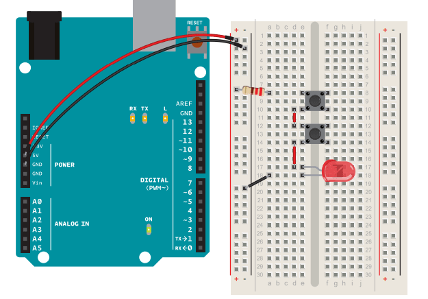
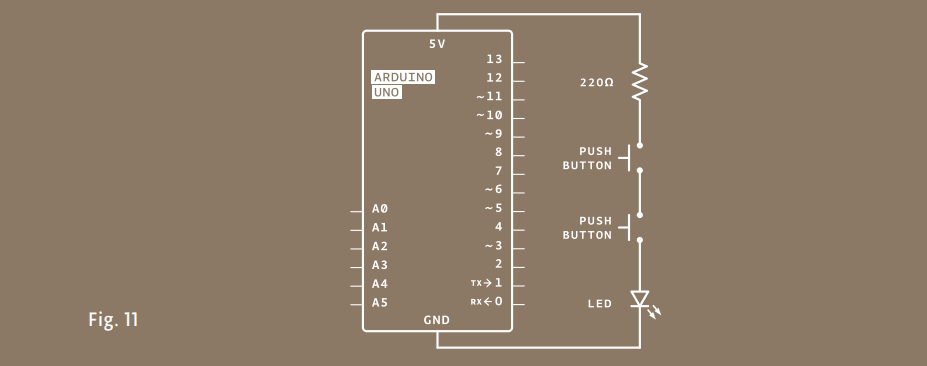
Once you’ve removed your power source add a switch next to the one already on your breadboard. Wire them together in series as shown in Fig. 10. Connect the anode (long leg) up the LED to the second switch. Connect the LED cathode to ground. Power up the Arduino again: now to turn on the LED, you need to press both switches. Since these are in series, they both need to be closed for the circuit to be completed.
ALWAYS REMOVE POWER BEFORE CHANGING ANYTHING IN YOUR CIRCUIT
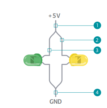
COMPONENTS IN PARALLEL RUN SIDE BY SIDE

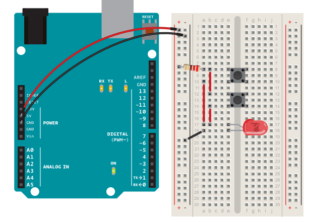
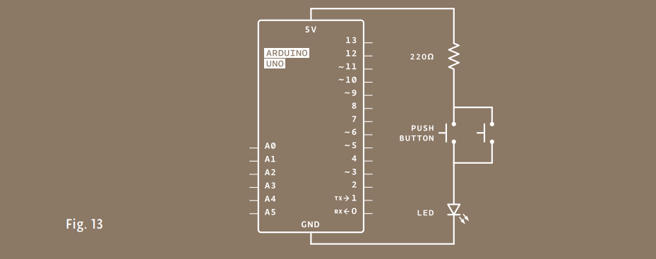
Now that you’ve mastered the art of things in series, it’s time to wire up switches in parallel. Keep the switches and LED where they are, but remove the connection between the two switches. Wire both switches to the resistor. Attach the other end of both switches to the LED, as shown in Fig. 12. Now when you press either button, the circuit is completed and the light turns on.
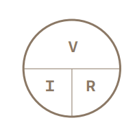
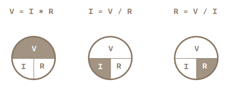
Current, voltage, and resistance are all related. When you change one of these in a circuit, it affects the others. The relationship between them is known as Ohm’s Law, named for Georg Simon Ohm, who discovered it.
VOLTAGE (V) = CURRENT (I) * RESISTANCE (R) When measuring amperage in the circuits you’ll be building, values will be in the milliamp range. That’s thousandths of one amp.
In the circuit shown in Fig. 5, you’re supplying 5 volts. The resistor offers 220 ohms resistance. To find the amperage used by the LED, replace the values in the equation. You should have 5=I*220. Dividing both sides of the equation by 220, you’ll find that I = .023. That’s 23 thousandths of an amp, or 23 milliamps (23 mA) used by the LED. That value is just about the maximum you can safely use with these LEDs, which is why you used a 220-ohm resistor.
You can expand this project in a number of ways, either by creating your own switch (two pieces of foil with wire work well), or creating a combination of switches and LEDs in parallel and series. What happens when you put three or four LEDs in series? What happens when they are in parallel?
Why does it behave the way it does? A multimeter is a tool that can verify the amount of resistance, current, and voltage in your circuit. While it’s not necessary to use one for these projects, it can be a useful part of any engineer’s toolbox. There’s a good description of how to use one online at arduino.cc/multimeter
You’ve learned about the electrical properties of voltage, current, and resistance while building a circuit on a breadboard. With some components like LEDs, resistors and switches, you created the simplest interactive system: a user presses the button, the lights turn on. These fundamentals of working with electronics will be referenced and expanded upon in the upcoming projects.