You will learn how an optocoupler works and why it is useful for controlling devices via Arduino, what components are needed to implement a circuit, how to connect an optocoupler to Arduino to control buttons on another device, what are some code examples for automating the process, and how to use this method in smart home, robotics, and automation projects.
Gain control over other components around you. Using additional electronic circuits, you can “push” buttons with Arduino.
Warning: You’re no longer a beginner if you’re doing this project. You’ll be opening up an electronic device and modifying it. You’ll void your device’s warranty, and if you’re not careful, you might damage the device. Make sure you’re familiar with all the electronics concepts in the earlier projects before you attempt this one. We recommend you use inexpensive items you don’t mind damaging for your first few projects, until you develop experience and confidence.
While the Arduino can control a lot of things, sometimes it’s easier to use tools that are created for specific purposes. Perhaps you want to control a television or a music player, or drive a remote control car. Most electronic devices have a control panel with buttons, and many of those buttons can be hacked so that you can “press” them with an Arduino. Controlling recorded sound is a good example. If you wanted to record and play back recorded sound, it would take a lot of effort to get the Arduino to do that. It’s much easier to get a small device that records and plays back sound, and replace its buttons with outputs controlled by your Arduino.
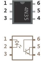
Optocouplers are integrated circuits that allow you to control one circuit from a different one without any electrical connection between the two. Inside an optocoupler is an LED and a light detector. When the LED in the optocoupler is turned on by your Arduino, the light detector closes a switch internally. The switch is connected to two of the output pins (4 and 5) of the optocoupler. When the internal switch is closed, the two output pins are connected. When the switch is open, they’re not connected. This way, it’s possible to close switches on other devices without connecting them to your Arduino.
In this example, the diagrams are for controlling a digital recording module that allows you to record and playback 20 seconds of sound, but the basic premise holds for any device that has a switch you can access. While it’s possible to use this example without soldering any wires, it certainly makes things easier. For more information on soldering, see p. 134.
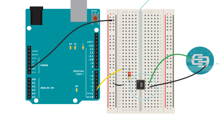
Connect ground to your breadboard through the Arduino.
Place the optocoupler on your breadboard so that it straddles the center of the board (see circuit diagram).
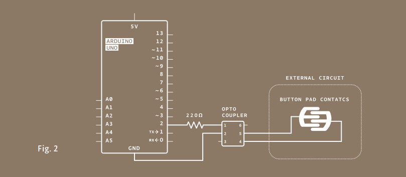
Connect pin 1 on the optocoupler to Arduino pin 2 in series with a 220-ohm resistor (remember, you’re powering an LED inside, you don’t want to burn it out). Connect pin 2 of the optocoupler to ground.
On the main board of the sound module there are a number of electrical components, including a playback button. To control the switch, you’re going to have to remove the button. Flip the circuit board over and find the tabs that hold the button in place. Gently bend the tabs back and remove the button from the board.
Under the button are two small metal plates. This pattern is typical of many electronic devices with pushbuttons. The two “forks” of this pattern are the two sides of the switch. A small metal disc inside the pushbutton connects these two forks when you press the button.
When the forks are connected, the switch is closed on the circuit board. You will be closing the switch with the optocoupler. This method, closing a switch with an optocoupler, works only if one of the two sides of the pushbutton’s switch is connected to ground on your device. If you’re not sure, take a multimeter and measure the voltage between one of the forks and the ground on your device. You need to do this with the device turned on, so be careful not to touch anywhere else on the board. Once you know which fork is ground, disconnect the power to your device.
Next, connect one wire to each of the small metal plates. If you are soldering these wires, be careful to not join the two sides of the switch together. If you are not soldering and using tape, make sure your connection is secure, or the switch won’t close. Make sure neither wire connects to the other fork, or your switch will be closed all the time.
Attach the two wires to pins 4 and 5 of the optocoupler. Connect the side of the switch that is grounded to pin 4 of the optocoupler. Connect the other fork to pin 5 of the optocoupler.
Name a constant. Most of the fun with this project is in the circuit and the optocoupler. The code is similar to the first project you made with the Arduino. You’re going to play the sound once every 20 seconds by turning pin 2 HIGH. Create a constant for the optocoupler control pin.
Configure the pin direction. In setup(), set the optocoupler pin into an output.
Pull the pin high and low. The loop() turns optoPin HIGH for a few milliseconds, long enough for the optocoupler to close the switch on the device. Then the optoPin becomes LOW.
Wait for a little while. Wait for 21 seconds for the whole message to play back before starting the loop() again.
Attach the battery to the sound recorder. Press and hold the record button on the device. While you’re holding the button, you can record audio into the microphone. Use your voice, the cat, or the pots and pans in the kitchen to make some noise (but be careful with the cat).
Once you’ve satisfactorily recorded a sound, power your Arduino with the USB cable. Your recording should start to play. If you recorded for the full 20 seconds, the sound should start again just a few moments after it ends.

Try experimenting with different sounds and durations of toggling the playback with the delay() in your program. If you trigger the switch while a sound is playing, it will stop. How can you take advantage of this to create unique sequences of sounds?
const int optoPin = 2;
void setup(){
 pinMode(optoPin, OUTPUT);
}
void loop(){
 digitalWrite(optoPin, HIGH);
 delay(15);
 digitalWrite(optoPin, LOW);
 delay(21000);
}

Integrated circuits are in virtually every electronic device. The large 28 pin chip on your Arduino is an IC that houses the brains of the board. There are other ICs that support this one with communication and power. The optocoupler and main chip on the Arduino are Dual In-line Package (DIP) chips. These DIP chips are the kind that most hobbyists use because they easily fit in a breadboard and don’t have to be permanently soldered to be used.

The project example only played sound back at a regular interval. How could you incorporate the inputs from earlier projects to trigger these sounds? What other battery powered things do you have around the house that need an Arduino to control them? This technique of controlling an electronic device with an optocoupler by connecting to the two sides of a switch can be used in many other devices. What other devices do you want to control?
Optocouplers can control devices that are on a different circuit. The two circuits are electrically separated from each other inside the component.